SlideShare a Scribd company logo
1 of 9
Download to read offline
Hardware Pack # 53426 Page1 OF 9
Read all the instructions before beginning.
Instruction # 53278
K&A Manufacturing
Assembly/Operation Instructions
NewHeights™ Series 4 XT
Elegante 4-Leg Conference Table
Make sure no obstacles are in the desk's path and all cords are of appropriate
length for the desk. Always maintain a 1" clearance around the table to prevent
pinching.
Never assemble (or disassemble) the table or components with the table plugged
into a power outlet. This product is for use on a nominal 120-volt circuit and has
a grounding plug. Make sure that the product is connected to an outlet having the
same configuration as the plug. No adapter should be used with this product.
Duty Cycle: 2 minutes ON/18 minutes OFF
Workstation can continuously operate for a maximum duration of two minutes.
After two minutes of non-stop operation, the workstation will automatically stop
and require eighteen minutes of cool down.
6703 Zinser Street
Schofield, WI 54476
Phone: 800.298.4351
Fax: 866.882.9475
www.raproducts.com
Version Dated: 8/16/16
in serious property damage or bodily injury.
instructions and warnings regarding the use of this product may result
Failure to comply with or observe all assembly, safety, and operation
WARNING !
Do not attempt to raise the
worksurface unless BOTH
control boxes are plugged
into a standard 110 volt
power source and all wiring
is complete as shown on
page 7.
Page 2 OF 9
K&A Manufacturing
6703 Zinser Street Schofield, WI 54476
Phone: 800.298.4351
Fax: 866.882.9475
www.raproducts.com
Tools Required for Assembly:
Power Driver W/Adjustable Torque
#2 Phillips Head Driver Bit or
#2 Square Head Driver Bit
3/16" Hex Head Driver Bit or
Allen Wrench
Tape Measure
Level
3 753638
53174 9 53176 11
8
Instruction # 53278
Hardware Pack # 53426
is drawn actual size.
ITEM # PART # DESCRIPTION QTY.
1 Varies Series 4 XT Conference Table Worksurface 1
2 801257 XT Conference 2 Column Leg Assembly 2
3 51708 M5 x 18mm (7/8") Sq/Ph/Wshr Head Wood Screw 52
4 Varies XT Wire Management Channel 2
5 Varies Series 4 Cross Support 2
6 Not Used
7 53638 5/16 x 3/8 Button Head Socket Cap Screw 16
8 800934 Cross Support End Cap 4
9 53174 1/4-20x1/2 Phillips Pan Head Machine Screw 4
10 Not Used
11 53176 .25x.696x.58 Flat Washer 4
12 50298 NewHeights Control Box 2
13 50072 8 x 3/4 Pan Head Recex Drive Screw 6
14 59169 Wire Management J 1
15 PSSM-4-2 Power Strip 4 Recps 2 USB Chargers 10 Ft Cord 1
16 53729 4 Position Programable Switch 1
17 52604 3/16" Cable Clamp 4
13
52604 17
51708
800943
1/2 Size
50072
Page 3 OF 9
K&A Manufacturing
6703 Zinser Street Schofield, WI 54476
Phone: 800.298.4351
Fax: 866.882.9475
www.raproducts.com
Instruction # 53278
Step 1: Lay the worksurface 1 on a protected surface with the pilot holes facing up.
Align the holes in the worksurface supports with the pilot holes in the worksurface.
Be careful to not pinch the motor wires between the motor boxes and the work-
surface. Do not allow the leg assemblies to stand without support. They could tip
over and the motor housings could crack. The grommets on the motor wires should
be in the square notches on the motor boxes. Attach the leg assemblies 2 to the
worksurface with (24) wood screws 3 . Leave the screws loose by about 1/8" so you
can adjust the leg assemblies when installing the wire management channels 4 and
the cross supports 5 .
Detail A
1
2
Step 1
A
3
Page 4 OF 9
K&A Manufacturing
6703 Zinser Street Schofield, WI 54476
Phone: 800.298.4351
Fax: 866.882.9475
www.raproducts.com
Step 2: Adjust one of the wire management channels
4 to align the holes in the channel with the holes on the
inside of the motor boxes. Insert (4) socket screws 7
through the holes near the ends of the channel and
thread them into the weld nuts on the motor boxes.
See Detail B. Do not fully tighten. Attach the wire
management channel to the worksurface with (5-10)
wood screws 3 . Do not fully tighten. Repeat Step 2
with the remaining wire management channel.
Step 2
Instruction # 53278
Detail B
7
4
1
4
3
2
B
Page 5 OF 9
K&A Manufacturing
6703 Zinser Street Schofield, WI 54476
Phone: 800.298.4351
Fax: 866.882.9475
www.raproducts.com
Step 3: Place (2) flat washers 11 on (2) machine screws
9 . Thread these into the cage nuts pre-installed in the
inner wire management channels and fully tighten. There
are (4) cage nuts in each inner wire management channel.
Use any (2) cage nuts that are accessible. See the back
view below left.
Step 4: Fully tighten the socket screws 7 holding the wire
management channels 4 to the motor boxes. Fully tighten
the wood screws holding the wire management channels
and the leg assemblies to the worksurface 1 . Do not over-
tighten the screws. Use a low torque setting on the power
driver.
Back View
11
9
Pre-installed
Cage Nuts
3
Steps 3 & 4
See back
view above.5
Instruction # 53278
8
7
Page 6 OF 9Instruction # 53278
Step 5: With the help of an assistant align one of the cross support with the stickers on
both leg assemblies. See below. Insert (4) socket screws 7 through the holes in the
ends of the cross support 5 and thread them into the weld nuts that are held in place by
the stickers. Do not fully tighten. Check that the cross support is level and parallel to the
worksurface. Fully tighten the socket screws.
Step 6: Repeat step 5 with the other cross support
All 4 legs
both cross
supports
Steps 5 & 6
Page 7 OF 9
K&A Manufacturing
6703 Zinser Street Schofield, WI 54476
Phone: 800.298.4351
Fax: 866.882.9475
www.raproducts.com
Step 7: Align the holes in the control boxes 12 with the
pilot holes in the worksurface 1 . Attach them with (2)
wood screws 3 in each. Align the holes in the
programmable switch 13 with the pilot holes in the work-
surface. Refer to the instructions for the attachment and
operation of the programmable switch. The control boxes
and switch can be mounted at any location on the work-
surface, wire lengths permitting.
Step 8: Attach the power strip 15 at the suggested location shown. It can be located
anywhere. Attach it with the (4) screws that came with the power strip.
Step 9: Attach the wire management J 14 at the location shown using (1) wood screw 3 .
No pilot hole is provided.
Instruction # 53278
WARNING !
DO NOT ATTEMPT TO
RAISE THE WORKSURFACE
UNLESS BOTH CONTROL
BOXES ARE PLUGGED INTO
A STANDARD 110 VOLT
POWER SOURCE AND ALL
WIRING IS COMPLETE AS
SHOWN ON PAGE 6.
Leveling Glide
Screws come
with power strip.
12
15
1413
16
Steps 7-9
3
17
13
Page 8 OF 9
K&A Manufacturing
6703 Zinser Street Schofield, WI 54476
Phone: 800.298.4351
Fax: 866.882.9475
www.raproducts.com
Step 10: Do not power up the control boxes until
all the wiring is in place as shown below. Run the
wires as shown in the schematic wire runs diagram below.
Run the wires in the wire management channels. Capture
the switch wire in the cable clamp 17 and attach it with (1)
wood screw 3 at the location shown. No pilot hole is
provided. Plug the wire from the programmable switch into
the receptacle labeled HS in control box A. Plug the motor
wires into the cables and plug the cables into the
receptacles labeled M1 & M2 on both control boxes 12 as
shown in the wiring diagram at left. Connect the control
boxes together with the cascading cable plugged into the
jacks on the top of the control boxes. Now the unit may
be powered up.
Step 11: With the help of an assistant, set the table
upright in its final location. Level the table if required by
turning the leveling glides clockwise (from the top) on the
low corners of the unit.
A
B
WARNING !
DO NOT ATTEMPT TO RAISE THE WORKSURFACE
UNLESS BOTH CONTROL BOXES ARE PLUGGED
INTO A STANDARD 110 VOLT POWER SOURCE AND
ALL WIRING IS COMPLETE AS SHOWN ON THIS PAGE.
Steps 10 & 11
A
B
HS M1 M2
M2 M1 HS
Motor
Wire
Motor
Wire
12
Switch Motor
Wire
Motor
Wire
Switch
Wire
Motor
Wire
Motor
Wire
Cascading
Cable
Power Cord
Control Box A
Power Cord
Control Box B
Power Cord
Power Strip
Motor
Wire
Motor
Wire
Instruction # 53278
17
Leveling Glide
Page 9 OF 9
K&A Manufacturing
6703 Zinser Street Schofield, WI 54476
Phone: 800.298.4351
Fax: 866.882.9475
www.raproducts.com
Instruction # 53278
Operation and Reset Procedure
Plug both power cords into a standard 110v receptacle. A power surge protector is
recommended. Press the down arrow button until the worksurface reaches its lowest
position and clicks. The NewHeights™ workstation is ready for use. If you unplug or
lose power and the unit does not operate, follow the reset procedure below
Reset Procedure: Unplug both power cords for 30 seconds and plug back in. Hold
the down arrow button until the unit stops at the bottom. Release the button; then
hold the down arrow button until the unit clicks twice.
Troubleshooting: If you are having any problems with the table operation, contact
RightAngle™ at 800-298-4351 or orders@raproducts.com.
Warranty Information: NewHeights™ products are warranted to be free of defects due
to manufacturing or materials as follows: Three years on the gear and/or motor(sw)
including the control boxes and hand switch. Five years on the support brackets,
aluminum columns and feet. We will replace any defective part after inspection by an
authorized agent. Costs incurred due to product replacement such as installation labor
or transportation are not covered under this warranty. When corresponding with
RightAngle™ products, record and provide the model and serial numbers located on
the control box.

More Related Content

Similar to XT Conference Table Assembly Guide

XT 2 Leg Conference Table Instructions
XT 2 Leg Conference Table InstructionsXT 2 Leg Conference Table Instructions
XT 2 Leg Conference Table InstructionsiMovR
 
Edwards Signaling MPSR1-S45W-GE Installation Manual
Edwards Signaling MPSR1-S45W-GE Installation ManualEdwards Signaling MPSR1-S45W-GE Installation Manual
Edwards Signaling MPSR1-S45W-GE Installation ManualJMAC Supply
 
G901 05 2013a
G901 05 2013aG901 05 2013a
G901 05 2013aRAYL_2014
 
3. Heat Shrink Cable Joint (HV) - 11kV 3 Core XLPE BS6622 Cables
3. Heat Shrink Cable Joint (HV) - 11kV 3 Core XLPE BS6622 Cables3. Heat Shrink Cable Joint (HV) - 11kV 3 Core XLPE BS6622 Cables
3. Heat Shrink Cable Joint (HV) - 11kV 3 Core XLPE BS6622 CablesThorne & Derrick International
 
Heat Shrink Cable Joint (HV) - 11kV 3 Core XLPE BS6622 Cables
Heat Shrink Cable Joint (HV) - 11kV 3 Core XLPE BS6622 CablesHeat Shrink Cable Joint (HV) - 11kV 3 Core XLPE BS6622 Cables
Heat Shrink Cable Joint (HV) - 11kV 3 Core XLPE BS6622 CablesThorne & Derrick International
 
Heat shrink cable joint (hv) 11k v 3 core xlpe bs6622 cables
Heat shrink cable joint (hv)   11k v 3 core xlpe bs6622 cablesHeat shrink cable joint (hv)   11k v 3 core xlpe bs6622 cables
Heat shrink cable joint (hv) 11k v 3 core xlpe bs6622 cablesThorne & Derrick International
 
11kV Heat Shrink Cable Terminations - Prysmian HIT3XB11 3 Core 35-70sqmm 11kV...
11kV Heat Shrink Cable Terminations - Prysmian HIT3XB11 3 Core 35-70sqmm 11kV...11kV Heat Shrink Cable Terminations - Prysmian HIT3XB11 3 Core 35-70sqmm 11kV...
11kV Heat Shrink Cable Terminations - Prysmian HIT3XB11 3 Core 35-70sqmm 11kV...Thorne & Derrick International
 
11kV Heat Shrink Cable Terminations - Prysmian HIT3XC11 3 Core 95-240sqmm 11k...
11kV Heat Shrink Cable Terminations - Prysmian HIT3XC11 3 Core 95-240sqmm 11k...11kV Heat Shrink Cable Terminations - Prysmian HIT3XC11 3 Core 95-240sqmm 11k...
11kV Heat Shrink Cable Terminations - Prysmian HIT3XC11 3 Core 95-240sqmm 11k...Thorne & Derrick International
 
Camden CM-324-4N Instruction Manual
Camden CM-324-4N Instruction ManualCamden CM-324-4N Instruction Manual
Camden CM-324-4N Instruction ManualJMAC Supply
 
Camden CM-325 Instruction Manual
Camden CM-325 Instruction ManualCamden CM-325 Instruction Manual
Camden CM-325 Instruction ManualJMAC Supply
 
Ultimaker original assembly_manual_v1.1
Ultimaker original assembly_manual_v1.1Ultimaker original assembly_manual_v1.1
Ultimaker original assembly_manual_v1.1Franck Lecluse
 
HydraForce PFPD assembly
HydraForce PFPD assemblyHydraForce PFPD assembly
HydraForce PFPD assemblyHenry Brewer
 
RAYCHEM TERMINATION KIT-TYCO TERMINATION-케이블 종단-거-瑞侃工具包电缆终端-阿克巴交易
RAYCHEM TERMINATION KIT-TYCO TERMINATION-케이블 종단-거-瑞侃工具包电缆终端-阿克巴交易RAYCHEM TERMINATION KIT-TYCO TERMINATION-케이블 종단-거-瑞侃工具包电缆终端-阿克巴交易
RAYCHEM TERMINATION KIT-TYCO TERMINATION-케이블 종단-거-瑞侃工具包电缆终端-阿克巴交易AKBAR TRADING
 
LoveShaw LD3 SBF with 60 Series Cartridge Manual
LoveShaw LD3 SBF with 60 Series Cartridge Manual LoveShaw LD3 SBF with 60 Series Cartridge Manual
LoveShaw LD3 SBF with 60 Series Cartridge Manual Pyramid Packaging Inc.
 
Liquid Nitrogen Pump Cooling System
Liquid Nitrogen Pump Cooling SystemLiquid Nitrogen Pump Cooling System
Liquid Nitrogen Pump Cooling SystemSima Umrao
 
CoFold Ultra Sliding Folding Door Gear Installation Instructions
CoFold Ultra Sliding Folding Door Gear Installation InstructionsCoFold Ultra Sliding Folding Door Gear Installation Instructions
CoFold Ultra Sliding Folding Door Gear Installation InstructionsCoastal Joinery Hardware
 
Paxton Access 921-161-US Instruction Manual
Paxton Access 921-161-US Instruction ManualPaxton Access 921-161-US Instruction Manual
Paxton Access 921-161-US Instruction ManualJMAC Supply
 

Similar to XT Conference Table Assembly Guide (20)

XT 2 Leg Conference Table Instructions
XT 2 Leg Conference Table InstructionsXT 2 Leg Conference Table Instructions
XT 2 Leg Conference Table Instructions
 
Edwards Signaling MPSR1-S45W-GE Installation Manual
Edwards Signaling MPSR1-S45W-GE Installation ManualEdwards Signaling MPSR1-S45W-GE Installation Manual
Edwards Signaling MPSR1-S45W-GE Installation Manual
 
G901 05 2013a
G901 05 2013aG901 05 2013a
G901 05 2013a
 
3. Heat Shrink Cable Joint (HV) - 11kV 3 Core XLPE BS6622 Cables
3. Heat Shrink Cable Joint (HV) - 11kV 3 Core XLPE BS6622 Cables3. Heat Shrink Cable Joint (HV) - 11kV 3 Core XLPE BS6622 Cables
3. Heat Shrink Cable Joint (HV) - 11kV 3 Core XLPE BS6622 Cables
 
Heat Shrink Cable Joint (HV) - 11kV 3 Core XLPE BS6622 Cables
Heat Shrink Cable Joint (HV) - 11kV 3 Core XLPE BS6622 CablesHeat Shrink Cable Joint (HV) - 11kV 3 Core XLPE BS6622 Cables
Heat Shrink Cable Joint (HV) - 11kV 3 Core XLPE BS6622 Cables
 
Heat shrink cable joint (hv) 11k v 3 core xlpe bs6622 cables
Heat shrink cable joint (hv)   11k v 3 core xlpe bs6622 cablesHeat shrink cable joint (hv)   11k v 3 core xlpe bs6622 cables
Heat shrink cable joint (hv) 11k v 3 core xlpe bs6622 cables
 
11kV Heat Shrink Cable Terminations - Prysmian HIT3XB11 3 Core 35-70sqmm 11kV...
11kV Heat Shrink Cable Terminations - Prysmian HIT3XB11 3 Core 35-70sqmm 11kV...11kV Heat Shrink Cable Terminations - Prysmian HIT3XB11 3 Core 35-70sqmm 11kV...
11kV Heat Shrink Cable Terminations - Prysmian HIT3XB11 3 Core 35-70sqmm 11kV...
 
11kV Heat Shrink Cable Terminations - Prysmian HIT3XC11 3 Core 95-240sqmm 11k...
11kV Heat Shrink Cable Terminations - Prysmian HIT3XC11 3 Core 95-240sqmm 11k...11kV Heat Shrink Cable Terminations - Prysmian HIT3XC11 3 Core 95-240sqmm 11k...
11kV Heat Shrink Cable Terminations - Prysmian HIT3XC11 3 Core 95-240sqmm 11k...
 
Camden CM-324-4N Instruction Manual
Camden CM-324-4N Instruction ManualCamden CM-324-4N Instruction Manual
Camden CM-324-4N Instruction Manual
 
Camden CM-325 Instruction Manual
Camden CM-325 Instruction ManualCamden CM-325 Instruction Manual
Camden CM-325 Instruction Manual
 
21915_r1
21915_r121915_r1
21915_r1
 
Ultimaker original assembly_manual_v1.1
Ultimaker original assembly_manual_v1.1Ultimaker original assembly_manual_v1.1
Ultimaker original assembly_manual_v1.1
 
HydraForce PFPD assembly
HydraForce PFPD assemblyHydraForce PFPD assembly
HydraForce PFPD assembly
 
RAYCHEM TERMINATION KIT-TYCO TERMINATION-케이블 종단-거-瑞侃工具包电缆终端-阿克巴交易
RAYCHEM TERMINATION KIT-TYCO TERMINATION-케이블 종단-거-瑞侃工具包电缆终端-阿克巴交易RAYCHEM TERMINATION KIT-TYCO TERMINATION-케이블 종단-거-瑞侃工具包电缆终端-阿克巴交易
RAYCHEM TERMINATION KIT-TYCO TERMINATION-케이블 종단-거-瑞侃工具包电缆终端-阿克巴交易
 
LoveShaw LD3 SBF with 60 Series Cartridge Manual
LoveShaw LD3 SBF with 60 Series Cartridge Manual LoveShaw LD3 SBF with 60 Series Cartridge Manual
LoveShaw LD3 SBF with 60 Series Cartridge Manual
 
Liquid Nitrogen Pump Cooling System
Liquid Nitrogen Pump Cooling SystemLiquid Nitrogen Pump Cooling System
Liquid Nitrogen Pump Cooling System
 
5 1375204-2-ds ok
5 1375204-2-ds ok5 1375204-2-ds ok
5 1375204-2-ds ok
 
CoFold Ultra Sliding Folding Door Gear Installation Instructions
CoFold Ultra Sliding Folding Door Gear Installation InstructionsCoFold Ultra Sliding Folding Door Gear Installation Instructions
CoFold Ultra Sliding Folding Door Gear Installation Instructions
 
Paxton Access 921-161-US Instruction Manual
Paxton Access 921-161-US Instruction ManualPaxton Access 921-161-US Instruction Manual
Paxton Access 921-161-US Instruction Manual
 
Distributor ariston tangerang 082113812149
Distributor ariston tangerang 082113812149Distributor ariston tangerang 082113812149
Distributor ariston tangerang 082113812149
 

More from iMovR

Lander Desk DIY Assembly Manual
Lander Desk DIY Assembly ManualLander Desk DIY Assembly Manual
Lander Desk DIY Assembly ManualiMovR
 
Lander L- & U-Desk Assembly Instructions and User Manual
Lander L- & U-Desk Assembly Instructions and User ManualLander L- & U-Desk Assembly Instructions and User Manual
Lander L- & U-Desk Assembly Instructions and User ManualiMovR
 
The Ensign's Standing Desk Installation and User Manual
The Ensign's Standing Desk Installation and User ManualThe Ensign's Standing Desk Installation and User Manual
The Ensign's Standing Desk Installation and User ManualiMovR
 
Lander Standing Desk User Manual
Lander Standing Desk User ManualLander Standing Desk User Manual
Lander Standing Desk User ManualiMovR
 
Lander Lite DIY Assembly Instructions Rev
Lander Lite DIY Assembly Instructions RevLander Lite DIY Assembly Instructions Rev
Lander Lite DIY Assembly Instructions ReviMovR
 
iMovR Premium Drawer Drill Template
iMovR Premium Drawer Drill TemplateiMovR Premium Drawer Drill Template
iMovR Premium Drawer Drill TemplateiMovR
 
Lander DIY Assembly Guide
Lander DIY Assembly GuideLander DIY Assembly Guide
Lander DIY Assembly GuideiMovR
 
Tech Dock Instruction Manual
Tech Dock Instruction ManualTech Dock Instruction Manual
Tech Dock Instruction ManualiMovR
 
Lander Lite Standing Desk User Manual
Lander Lite Standing Desk User ManualLander Lite Standing Desk User Manual
Lander Lite Standing Desk User ManualiMovR
 
Standing mat-study-texas-am-university-2013
Standing mat-study-texas-am-university-2013Standing mat-study-texas-am-university-2013
Standing mat-study-texas-am-university-2013iMovR
 
INSTALLATION INSTRUCTIONS RONDO MICRO PASS-THROUGH GROMMET WITH COVER (NO POWER)
INSTALLATION INSTRUCTIONS RONDO MICRO PASS-THROUGH GROMMET WITH COVER (NO POWER)INSTALLATION INSTRUCTIONS RONDO MICRO PASS-THROUGH GROMMET WITH COVER (NO POWER)
INSTALLATION INSTRUCTIONS RONDO MICRO PASS-THROUGH GROMMET WITH COVER (NO POWER)iMovR
 
Spacer kit instructions
Spacer kit instructions Spacer kit instructions
Spacer kit instructions iMovR
 
Installation Instructions for Rondo Micro USB-C 18W and 60W
Installation Instructions for Rondo Micro USB-C 18W and 60WInstallation Instructions for Rondo Micro USB-C 18W and 60W
Installation Instructions for Rondo Micro USB-C 18W and 60WiMovR
 
Captains Desk Instruction Manual
 Captains Desk Instruction Manual  Captains Desk Instruction Manual
Captains Desk Instruction Manual iMovR
 
Rondo Micro USB-C 18W Instruction Manual
Rondo Micro USB-C 18W Instruction ManualRondo Micro USB-C 18W Instruction Manual
Rondo Micro USB-C 18W Instruction ManualiMovR
 
Rondo Micro AC Outlet Instruction Manual
Rondo Micro AC Outlet Instruction ManualRondo Micro AC Outlet Instruction Manual
Rondo Micro AC Outlet Instruction ManualiMovR
 
Captain's Desk Standing Desk Instruction Manual
Captain's Desk Standing Desk Instruction ManualCaptain's Desk Standing Desk Instruction Manual
Captain's Desk Standing Desk Instruction ManualiMovR
 
Stowaway Ergonomic Keyboard Tray Installation Manual
Stowaway Ergonomic Keyboard Tray Installation ManualStowaway Ergonomic Keyboard Tray Installation Manual
Stowaway Ergonomic Keyboard Tray Installation ManualiMovR
 
Neemo Ergonomic Chair User Guide
Neemo Ergonomic Chair User GuideNeemo Ergonomic Chair User Guide
Neemo Ergonomic Chair User GuideiMovR
 
iMovR Lander L-Desk Instruction Manual (w or w/o built-in SteadyType Keyboard...
iMovR Lander L-Desk Instruction Manual (w or w/o built-in SteadyType Keyboard...iMovR Lander L-Desk Instruction Manual (w or w/o built-in SteadyType Keyboard...
iMovR Lander L-Desk Instruction Manual (w or w/o built-in SteadyType Keyboard...iMovR
 

More from iMovR (20)

Lander Desk DIY Assembly Manual
Lander Desk DIY Assembly ManualLander Desk DIY Assembly Manual
Lander Desk DIY Assembly Manual
 
Lander L- & U-Desk Assembly Instructions and User Manual
Lander L- & U-Desk Assembly Instructions and User ManualLander L- & U-Desk Assembly Instructions and User Manual
Lander L- & U-Desk Assembly Instructions and User Manual
 
The Ensign's Standing Desk Installation and User Manual
The Ensign's Standing Desk Installation and User ManualThe Ensign's Standing Desk Installation and User Manual
The Ensign's Standing Desk Installation and User Manual
 
Lander Standing Desk User Manual
Lander Standing Desk User ManualLander Standing Desk User Manual
Lander Standing Desk User Manual
 
Lander Lite DIY Assembly Instructions Rev
Lander Lite DIY Assembly Instructions RevLander Lite DIY Assembly Instructions Rev
Lander Lite DIY Assembly Instructions Rev
 
iMovR Premium Drawer Drill Template
iMovR Premium Drawer Drill TemplateiMovR Premium Drawer Drill Template
iMovR Premium Drawer Drill Template
 
Lander DIY Assembly Guide
Lander DIY Assembly GuideLander DIY Assembly Guide
Lander DIY Assembly Guide
 
Tech Dock Instruction Manual
Tech Dock Instruction ManualTech Dock Instruction Manual
Tech Dock Instruction Manual
 
Lander Lite Standing Desk User Manual
Lander Lite Standing Desk User ManualLander Lite Standing Desk User Manual
Lander Lite Standing Desk User Manual
 
Standing mat-study-texas-am-university-2013
Standing mat-study-texas-am-university-2013Standing mat-study-texas-am-university-2013
Standing mat-study-texas-am-university-2013
 
INSTALLATION INSTRUCTIONS RONDO MICRO PASS-THROUGH GROMMET WITH COVER (NO POWER)
INSTALLATION INSTRUCTIONS RONDO MICRO PASS-THROUGH GROMMET WITH COVER (NO POWER)INSTALLATION INSTRUCTIONS RONDO MICRO PASS-THROUGH GROMMET WITH COVER (NO POWER)
INSTALLATION INSTRUCTIONS RONDO MICRO PASS-THROUGH GROMMET WITH COVER (NO POWER)
 
Spacer kit instructions
Spacer kit instructions Spacer kit instructions
Spacer kit instructions
 
Installation Instructions for Rondo Micro USB-C 18W and 60W
Installation Instructions for Rondo Micro USB-C 18W and 60WInstallation Instructions for Rondo Micro USB-C 18W and 60W
Installation Instructions for Rondo Micro USB-C 18W and 60W
 
Captains Desk Instruction Manual
 Captains Desk Instruction Manual  Captains Desk Instruction Manual
Captains Desk Instruction Manual
 
Rondo Micro USB-C 18W Instruction Manual
Rondo Micro USB-C 18W Instruction ManualRondo Micro USB-C 18W Instruction Manual
Rondo Micro USB-C 18W Instruction Manual
 
Rondo Micro AC Outlet Instruction Manual
Rondo Micro AC Outlet Instruction ManualRondo Micro AC Outlet Instruction Manual
Rondo Micro AC Outlet Instruction Manual
 
Captain's Desk Standing Desk Instruction Manual
Captain's Desk Standing Desk Instruction ManualCaptain's Desk Standing Desk Instruction Manual
Captain's Desk Standing Desk Instruction Manual
 
Stowaway Ergonomic Keyboard Tray Installation Manual
Stowaway Ergonomic Keyboard Tray Installation ManualStowaway Ergonomic Keyboard Tray Installation Manual
Stowaway Ergonomic Keyboard Tray Installation Manual
 
Neemo Ergonomic Chair User Guide
Neemo Ergonomic Chair User GuideNeemo Ergonomic Chair User Guide
Neemo Ergonomic Chair User Guide
 
iMovR Lander L-Desk Instruction Manual (w or w/o built-in SteadyType Keyboard...
iMovR Lander L-Desk Instruction Manual (w or w/o built-in SteadyType Keyboard...iMovR Lander L-Desk Instruction Manual (w or w/o built-in SteadyType Keyboard...
iMovR Lander L-Desk Instruction Manual (w or w/o built-in SteadyType Keyboard...
 

Recently uploaded

Best VIP Call Girls Noida Sector 50 Call Me: 8448380779
Best VIP Call Girls Noida Sector 50 Call Me: 8448380779Best VIP Call Girls Noida Sector 50 Call Me: 8448380779
Best VIP Call Girls Noida Sector 50 Call Me: 8448380779Delhi Call girls
 
Best VIP Call Girls Noida Sector 55 Call Me: 8448380779
Best VIP Call Girls Noida Sector 55 Call Me: 8448380779Best VIP Call Girls Noida Sector 55 Call Me: 8448380779
Best VIP Call Girls Noida Sector 55 Call Me: 8448380779Delhi Call girls
 
Top Rated Pune Call Girls Talegaon Dabhade ⟟ 6297143586 ⟟ Call Me For Genuin...
Top Rated  Pune Call Girls Talegaon Dabhade ⟟ 6297143586 ⟟ Call Me For Genuin...Top Rated  Pune Call Girls Talegaon Dabhade ⟟ 6297143586 ⟟ Call Me For Genuin...
Top Rated Pune Call Girls Talegaon Dabhade ⟟ 6297143586 ⟟ Call Me For Genuin...Call Girls in Nagpur High Profile
 
Supermarket Floral Ad Roundup- Week 17 2024.pdf
Supermarket Floral Ad Roundup- Week 17 2024.pdfSupermarket Floral Ad Roundup- Week 17 2024.pdf
Supermarket Floral Ad Roundup- Week 17 2024.pdfKarliNelson4
 
The 15 Minute Breakdown: 2024 Beauty Marketing Study
The 15 Minute Breakdown: 2024 Beauty Marketing StudyThe 15 Minute Breakdown: 2024 Beauty Marketing Study
The 15 Minute Breakdown: 2024 Beauty Marketing StudyTinuiti
 
Film= Dubai Call Girls O525547819 Call Girls Dubai Whsatapp
Film= Dubai Call Girls O525547819 Call Girls Dubai WhsatappFilm= Dubai Call Girls O525547819 Call Girls Dubai Whsatapp
Film= Dubai Call Girls O525547819 Call Girls Dubai Whsatappkojalkojal131
 
The 15 Minute Breakdown: 2024 Beauty Marketing Study
The 15 Minute Breakdown: 2024 Beauty Marketing StudyThe 15 Minute Breakdown: 2024 Beauty Marketing Study
The 15 Minute Breakdown: 2024 Beauty Marketing StudyKatherineBishop4
 
Best VIP Call Girls Noida Sector 51 Call Me: 8448380779
Best VIP Call Girls Noida Sector 51 Call Me: 8448380779Best VIP Call Girls Noida Sector 51 Call Me: 8448380779
Best VIP Call Girls Noida Sector 51 Call Me: 8448380779Delhi Call girls
 
Indian Call Girl In Dubai #$# O5634O3O18 #$# Dubai Call Girl
Indian Call Girl In Dubai #$# O5634O3O18 #$# Dubai Call GirlIndian Call Girl In Dubai #$# O5634O3O18 #$# Dubai Call Girl
Indian Call Girl In Dubai #$# O5634O3O18 #$# Dubai Call GirlAroojKhan71
 
Dubai Call Girls O525547&19 (Asii) Call Girls Dubai
Dubai Call Girls O525547&19 (Asii) Call Girls DubaiDubai Call Girls O525547&19 (Asii) Call Girls Dubai
Dubai Call Girls O525547&19 (Asii) Call Girls Dubaikojalkojal131
 

Recently uploaded (10)

Best VIP Call Girls Noida Sector 50 Call Me: 8448380779
Best VIP Call Girls Noida Sector 50 Call Me: 8448380779Best VIP Call Girls Noida Sector 50 Call Me: 8448380779
Best VIP Call Girls Noida Sector 50 Call Me: 8448380779
 
Best VIP Call Girls Noida Sector 55 Call Me: 8448380779
Best VIP Call Girls Noida Sector 55 Call Me: 8448380779Best VIP Call Girls Noida Sector 55 Call Me: 8448380779
Best VIP Call Girls Noida Sector 55 Call Me: 8448380779
 
Top Rated Pune Call Girls Talegaon Dabhade ⟟ 6297143586 ⟟ Call Me For Genuin...
Top Rated  Pune Call Girls Talegaon Dabhade ⟟ 6297143586 ⟟ Call Me For Genuin...Top Rated  Pune Call Girls Talegaon Dabhade ⟟ 6297143586 ⟟ Call Me For Genuin...
Top Rated Pune Call Girls Talegaon Dabhade ⟟ 6297143586 ⟟ Call Me For Genuin...
 
Supermarket Floral Ad Roundup- Week 17 2024.pdf
Supermarket Floral Ad Roundup- Week 17 2024.pdfSupermarket Floral Ad Roundup- Week 17 2024.pdf
Supermarket Floral Ad Roundup- Week 17 2024.pdf
 
The 15 Minute Breakdown: 2024 Beauty Marketing Study
The 15 Minute Breakdown: 2024 Beauty Marketing StudyThe 15 Minute Breakdown: 2024 Beauty Marketing Study
The 15 Minute Breakdown: 2024 Beauty Marketing Study
 
Film= Dubai Call Girls O525547819 Call Girls Dubai Whsatapp
Film= Dubai Call Girls O525547819 Call Girls Dubai WhsatappFilm= Dubai Call Girls O525547819 Call Girls Dubai Whsatapp
Film= Dubai Call Girls O525547819 Call Girls Dubai Whsatapp
 
The 15 Minute Breakdown: 2024 Beauty Marketing Study
The 15 Minute Breakdown: 2024 Beauty Marketing StudyThe 15 Minute Breakdown: 2024 Beauty Marketing Study
The 15 Minute Breakdown: 2024 Beauty Marketing Study
 
Best VIP Call Girls Noida Sector 51 Call Me: 8448380779
Best VIP Call Girls Noida Sector 51 Call Me: 8448380779Best VIP Call Girls Noida Sector 51 Call Me: 8448380779
Best VIP Call Girls Noida Sector 51 Call Me: 8448380779
 
Indian Call Girl In Dubai #$# O5634O3O18 #$# Dubai Call Girl
Indian Call Girl In Dubai #$# O5634O3O18 #$# Dubai Call GirlIndian Call Girl In Dubai #$# O5634O3O18 #$# Dubai Call Girl
Indian Call Girl In Dubai #$# O5634O3O18 #$# Dubai Call Girl
 
Dubai Call Girls O525547&19 (Asii) Call Girls Dubai
Dubai Call Girls O525547&19 (Asii) Call Girls DubaiDubai Call Girls O525547&19 (Asii) Call Girls Dubai
Dubai Call Girls O525547&19 (Asii) Call Girls Dubai
 

XT Conference Table Assembly Guide

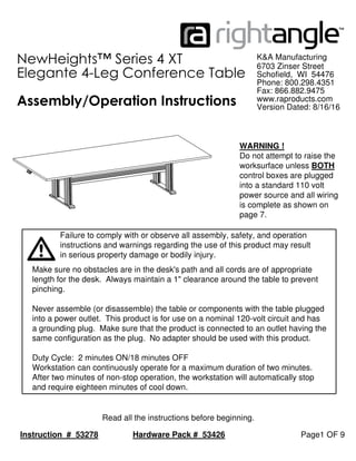
  • 1. Hardware Pack # 53426 Page1 OF 9 Read all the instructions before beginning. Instruction # 53278 K&A Manufacturing Assembly/Operation Instructions NewHeights™ Series 4 XT Elegante 4-Leg Conference Table Make sure no obstacles are in the desk's path and all cords are of appropriate length for the desk. Always maintain a 1" clearance around the table to prevent pinching. Never assemble (or disassemble) the table or components with the table plugged into a power outlet. This product is for use on a nominal 120-volt circuit and has a grounding plug. Make sure that the product is connected to an outlet having the same configuration as the plug. No adapter should be used with this product. Duty Cycle: 2 minutes ON/18 minutes OFF Workstation can continuously operate for a maximum duration of two minutes. After two minutes of non-stop operation, the workstation will automatically stop and require eighteen minutes of cool down. 6703 Zinser Street Schofield, WI 54476 Phone: 800.298.4351 Fax: 866.882.9475 www.raproducts.com Version Dated: 8/16/16 in serious property damage or bodily injury. instructions and warnings regarding the use of this product may result Failure to comply with or observe all assembly, safety, and operation WARNING ! Do not attempt to raise the worksurface unless BOTH control boxes are plugged into a standard 110 volt power source and all wiring is complete as shown on page 7.
  • 2. Page 2 OF 9 K&A Manufacturing 6703 Zinser Street Schofield, WI 54476 Phone: 800.298.4351 Fax: 866.882.9475 www.raproducts.com Tools Required for Assembly: Power Driver W/Adjustable Torque #2 Phillips Head Driver Bit or #2 Square Head Driver Bit 3/16" Hex Head Driver Bit or Allen Wrench Tape Measure Level 3 753638 53174 9 53176 11 8 Instruction # 53278 Hardware Pack # 53426 is drawn actual size. ITEM # PART # DESCRIPTION QTY. 1 Varies Series 4 XT Conference Table Worksurface 1 2 801257 XT Conference 2 Column Leg Assembly 2 3 51708 M5 x 18mm (7/8") Sq/Ph/Wshr Head Wood Screw 52 4 Varies XT Wire Management Channel 2 5 Varies Series 4 Cross Support 2 6 Not Used 7 53638 5/16 x 3/8 Button Head Socket Cap Screw 16 8 800934 Cross Support End Cap 4 9 53174 1/4-20x1/2 Phillips Pan Head Machine Screw 4 10 Not Used 11 53176 .25x.696x.58 Flat Washer 4 12 50298 NewHeights Control Box 2 13 50072 8 x 3/4 Pan Head Recex Drive Screw 6 14 59169 Wire Management J 1 15 PSSM-4-2 Power Strip 4 Recps 2 USB Chargers 10 Ft Cord 1 16 53729 4 Position Programable Switch 1 17 52604 3/16" Cable Clamp 4 13 52604 17 51708 800943 1/2 Size 50072
  • 3. Page 3 OF 9 K&A Manufacturing 6703 Zinser Street Schofield, WI 54476 Phone: 800.298.4351 Fax: 866.882.9475 www.raproducts.com Instruction # 53278 Step 1: Lay the worksurface 1 on a protected surface with the pilot holes facing up. Align the holes in the worksurface supports with the pilot holes in the worksurface. Be careful to not pinch the motor wires between the motor boxes and the work- surface. Do not allow the leg assemblies to stand without support. They could tip over and the motor housings could crack. The grommets on the motor wires should be in the square notches on the motor boxes. Attach the leg assemblies 2 to the worksurface with (24) wood screws 3 . Leave the screws loose by about 1/8" so you can adjust the leg assemblies when installing the wire management channels 4 and the cross supports 5 . Detail A 1 2 Step 1 A 3
  • 4. Page 4 OF 9 K&A Manufacturing 6703 Zinser Street Schofield, WI 54476 Phone: 800.298.4351 Fax: 866.882.9475 www.raproducts.com Step 2: Adjust one of the wire management channels 4 to align the holes in the channel with the holes on the inside of the motor boxes. Insert (4) socket screws 7 through the holes near the ends of the channel and thread them into the weld nuts on the motor boxes. See Detail B. Do not fully tighten. Attach the wire management channel to the worksurface with (5-10) wood screws 3 . Do not fully tighten. Repeat Step 2 with the remaining wire management channel. Step 2 Instruction # 53278 Detail B 7 4 1 4 3 2 B
  • 5. Page 5 OF 9 K&A Manufacturing 6703 Zinser Street Schofield, WI 54476 Phone: 800.298.4351 Fax: 866.882.9475 www.raproducts.com Step 3: Place (2) flat washers 11 on (2) machine screws 9 . Thread these into the cage nuts pre-installed in the inner wire management channels and fully tighten. There are (4) cage nuts in each inner wire management channel. Use any (2) cage nuts that are accessible. See the back view below left. Step 4: Fully tighten the socket screws 7 holding the wire management channels 4 to the motor boxes. Fully tighten the wood screws holding the wire management channels and the leg assemblies to the worksurface 1 . Do not over- tighten the screws. Use a low torque setting on the power driver. Back View 11 9 Pre-installed Cage Nuts 3 Steps 3 & 4 See back view above.5 Instruction # 53278 8 7
  • 6. Page 6 OF 9Instruction # 53278 Step 5: With the help of an assistant align one of the cross support with the stickers on both leg assemblies. See below. Insert (4) socket screws 7 through the holes in the ends of the cross support 5 and thread them into the weld nuts that are held in place by the stickers. Do not fully tighten. Check that the cross support is level and parallel to the worksurface. Fully tighten the socket screws. Step 6: Repeat step 5 with the other cross support All 4 legs both cross supports Steps 5 & 6
  • 7. Page 7 OF 9 K&A Manufacturing 6703 Zinser Street Schofield, WI 54476 Phone: 800.298.4351 Fax: 866.882.9475 www.raproducts.com Step 7: Align the holes in the control boxes 12 with the pilot holes in the worksurface 1 . Attach them with (2) wood screws 3 in each. Align the holes in the programmable switch 13 with the pilot holes in the work- surface. Refer to the instructions for the attachment and operation of the programmable switch. The control boxes and switch can be mounted at any location on the work- surface, wire lengths permitting. Step 8: Attach the power strip 15 at the suggested location shown. It can be located anywhere. Attach it with the (4) screws that came with the power strip. Step 9: Attach the wire management J 14 at the location shown using (1) wood screw 3 . No pilot hole is provided. Instruction # 53278 WARNING ! DO NOT ATTEMPT TO RAISE THE WORKSURFACE UNLESS BOTH CONTROL BOXES ARE PLUGGED INTO A STANDARD 110 VOLT POWER SOURCE AND ALL WIRING IS COMPLETE AS SHOWN ON PAGE 6. Leveling Glide Screws come with power strip. 12 15 1413 16 Steps 7-9 3 17 13
  • 8. Page 8 OF 9 K&A Manufacturing 6703 Zinser Street Schofield, WI 54476 Phone: 800.298.4351 Fax: 866.882.9475 www.raproducts.com Step 10: Do not power up the control boxes until all the wiring is in place as shown below. Run the wires as shown in the schematic wire runs diagram below. Run the wires in the wire management channels. Capture the switch wire in the cable clamp 17 and attach it with (1) wood screw 3 at the location shown. No pilot hole is provided. Plug the wire from the programmable switch into the receptacle labeled HS in control box A. Plug the motor wires into the cables and plug the cables into the receptacles labeled M1 & M2 on both control boxes 12 as shown in the wiring diagram at left. Connect the control boxes together with the cascading cable plugged into the jacks on the top of the control boxes. Now the unit may be powered up. Step 11: With the help of an assistant, set the table upright in its final location. Level the table if required by turning the leveling glides clockwise (from the top) on the low corners of the unit. A B WARNING ! DO NOT ATTEMPT TO RAISE THE WORKSURFACE UNLESS BOTH CONTROL BOXES ARE PLUGGED INTO A STANDARD 110 VOLT POWER SOURCE AND ALL WIRING IS COMPLETE AS SHOWN ON THIS PAGE. Steps 10 & 11 A B HS M1 M2 M2 M1 HS Motor Wire Motor Wire 12 Switch Motor Wire Motor Wire Switch Wire Motor Wire Motor Wire Cascading Cable Power Cord Control Box A Power Cord Control Box B Power Cord Power Strip Motor Wire Motor Wire Instruction # 53278 17 Leveling Glide
  • 9. Page 9 OF 9 K&A Manufacturing 6703 Zinser Street Schofield, WI 54476 Phone: 800.298.4351 Fax: 866.882.9475 www.raproducts.com Instruction # 53278 Operation and Reset Procedure Plug both power cords into a standard 110v receptacle. A power surge protector is recommended. Press the down arrow button until the worksurface reaches its lowest position and clicks. The NewHeights™ workstation is ready for use. If you unplug or lose power and the unit does not operate, follow the reset procedure below Reset Procedure: Unplug both power cords for 30 seconds and plug back in. Hold the down arrow button until the unit stops at the bottom. Release the button; then hold the down arrow button until the unit clicks twice. Troubleshooting: If you are having any problems with the table operation, contact RightAngle™ at 800-298-4351 or orders@raproducts.com. Warranty Information: NewHeights™ products are warranted to be free of defects due to manufacturing or materials as follows: Three years on the gear and/or motor(sw) including the control boxes and hand switch. Five years on the support brackets, aluminum columns and feet. We will replace any defective part after inspection by an authorized agent. Costs incurred due to product replacement such as installation labor or transportation are not covered under this warranty. When corresponding with RightAngle™ products, record and provide the model and serial numbers located on the control box.