1. 6710 N CATLIN AVE. • PORTLAND, OR 97203 • 503-283-4335 • 1-800-234-8920 (USA AND CANADA) • FAX 503-283-3007
Bushwacker only approves installing the flares according to these
written instructions with the hardware provided. WARNING: Failure
to install according to these instructions will invalidate the warranty.
This includes, but is not limited to using alternative installation
methods, hardware, or materials. DO NOT USE: Loctite, SuperGlue,
or similar products on the hardware or the flares.
Fit: Verify the fit of the flares to vehicle. (Some filing, sanding, or
cutting may be necessary to ensure proper fit).
Painting:(Optional)ifpaintisdesireditmustbedonepriortoinstallingflares
onvehicle.Cleanoutersurfacewithagoodgradedegreaser.DONOTUSE
LACQUERTHINNERORENAMELREDUCERASADEGREASER.Wipe
outer surface thoroughly with a tack rag prior to paint. Application of plastic
adhesion promoter forABS plastic as per your paint system manufacturer’s
recommendations is required. Paint flares using a high quality enamel, or
polyurethane automotive paint. If painting edge trim (not recommended),
use a flex additive.
Performance: Using larger Tires may increase the area required to
turn the vehicle. Some Tire/Rim combinations may require lowering
bump stops and or installing steering stops to prevent tire from
contacting flare.
Exhaust System: Modifications may be necessary to maintain a
minimum 4” clearance between flares and exhaust pipes. (Exhaust
gases should not vent directly onto flares)
Metal Protection: All exposed fasteners and bare metal should
be treated with rust resistant paint BEFORE installing flares. Spray
inner fender wells with undercoating AFTER flare attachments have
been completed.
Decals: Flares may interfere with existing decals on vehicle. If you
wish, remove decals prior to installation of flares.
STEP 1 – PRIOR TO INSTALLATION
A)
B)
C)
D)
E)
F)
G)
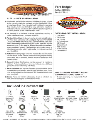
Ford Ranger
Utility Knife
Elecrtic Drill
1/4” Drill Bit
#2 Phillips Driver
1/2” Wrench
Socket Wrench
7/32” Socket
10 mm Socket
Grease Pencil
Set Part #21915-02
Rev-1 07-06-11
TOOLS FOR EASY INSTALLATION:
•
•
•
•
•
•
•
•
•
To claim a warranty, you must provide Proof
of Purchase.
LIMITED LIFETIME WARRANTY AGAINST
ANY MANUFACTURING DEFECTS
•
14 pcs 4 pcs10 pcs
32 pcs
32 pcs
32 pcs
1 pc
4.
9.8.
6.
10.
8 pcs 2 pcs
4 pcs
1 pc
271 in
1. 7.
11. 12.
2. 5.3.
Included in Hardware Kit:
2. 6710 N CATLIN AVE. • PORTLAND, OR 97203 • 503-283-4335 • 1-800-234-8920 (USA AND CANADA) • FAX 503-283-3007
Component List
Put each Bolt/Washer combination through a pocket
hole in the flare, Bolt head and Washer on the
outside.
Put a Washer (WA1-0012) on each Bolt (SW1-0059).
21
Front & Rear Flare Pocket Hardware Installation
Peel two to three inches of red vinyl backing away from Edge Trim
(GP1-0005) tape. Applying the adhesive side of the edge trim to the
inner side of the flare, affix the edge trim to the top edge of the flare (the
portion that comes in contact with the vehicle).
Press edge trim into place along the top edge of the flare in one-foot
increments, pulling red vinyl backing free as you continue to work your
way around the top edge of the flare.
STEP 2 - EDGE TRIM INSTALLATION
A)
B)
Left Front
Flare
Right Front
Flare
Left Rear
Flare
Right Rear
Flare
Right Front
Inner Piece
Left Front
Inner Piece
1. 2. 3. 4.
5. 6.
3. 6710 N CATLIN AVE. • PORTLAND, OR 97203 • 503-283-4335 • 1-800-234-8920 (USA AND CANADA) • FAX 503-283-3007
Place a Nut (NU1-0019) over the end of each Bolt
and tighten, using a 1/2” wrench for the Nut and the
supplied Torx Bit (SW1-0052) for the Bolt. Repeat for
remaining pockets.
3
Remove factory flare, mud flap, or rock guard and
clean wheel well opening. Remove two fender inner
liner factory screws with a 7/32” socket wrench. Save
screws for reinstallation.
4
Front Flare Installation Procedures (Driver’s Side)
Install Clips (CL1-0022) on inner piece over the
holes. (2 Locations)
5
Install inner piece by hand starting factory screws,
saved from Step 4, into factory holes.
Install Tab (MT1-0002) on sheet metal between inner
piece and wheel well at two inner piece Clip (CL1-
0022) locations. Tighten factory screws.
6 7
4. 6710 N CATLIN AVE. • PORTLAND, OR 97203 • 503-283-4335 • 1-800-234-8920 (USA AND CANADA) • FAX 503-283-3007
Install a Tab (MT1-0002) centered over mark made
in Step 9. Edge of Tab should be even with edge of
sheet metal.
Remove factory screw at rear of wheel well. Save for
reinstallation.
Hold flare to vehicle and mark second rearmost hole
location with grease pencil.
Install a Clip (CL1-0006) over the Tab installed in
Step 10.
Hold flare in place and start Screws (SW1-0058) in
Clip (CL1-0022) locations and into inner piece. Do
not tighten.
Start Screw (SW1-0050) into Clip (CL1-0006)
installed in Step 11. Do not tighten.
8
10
12
9
11
13
5. 6710 N CATLIN AVE. • PORTLAND, OR 97203 • 503-283-4335 • 1-800-234-8920 (USA AND CANADA) • FAX 503-283-3007
Reinstall factory screw saved from Step 8. Ensuring proper flare placement, tighten all screws.
Completed front flare installation.
14
16
15
Position flare on fender ensuring that fender brace
bolt is through the flare’s bottom pocket.
18
Brace Bolt
Brace
Nut
Remove any installed factory flares, mud flaps, or
stone guards and clean wheel well opening. Remove
rear Fender Brace Nut with a 13mm socket. Save
brace nut for reinstallation.
17
Rear Flare Installation Procedures (Driver’s Side)
6. 6710 N CATLIN AVE. • PORTLAND, OR 97203 • 503-283-4335 • 1-800-234-8920 (USA AND CANADA) • FAX 503-283-3007
Start Fender Brace Nut removed in Step 17 on
fender brace bolt.
Ensure proper placement of flare and tighten all
screws and the brace nut.
23 23
Install an Clip (CL1-0005) over each of the Tabs
installed in Step 20.
Install a Tab (MT1-0002) centered over each of the
four holes marked in Step 19. Edge of Tab should be
even with edge of sheet metal.
21
20
Mark through all flare holes using a grease pencil.
Remove Flare.
19
Reposition flare on fender ensuring that fender brace
bolt is through lowest rearward hole and, starting
with the rearmost wheel well hole, start Screws
(SW1-0050) through holes in flare and into Clips
(CL1-0022) with a #2 Phillips screwdriver.
22
7. 6710 N CATLIN AVE. • PORTLAND, OR 97203 • 503-283-4335 • 1-800-234-8920 (USA AND CANADA) • FAX 503-283-3007
Using flat end of supplied Edge Trim Tool (ET1-0002),
seat edge trim against flare by inserting straight end
between edge trim and flare at one end. Next, slide
around entire edge to the other end.
Using supplied Edge Trim Tool (ET1-0002), seat
edge trim against vehicle by hooking curved end
under edge trim at one end of flare. Next, slide
around outer edge of flare to the other end.
2625
Front & Rear Edge Trim Tool Procedures
Completed rear flare installation.
24
8. 6710 N CATLIN AVE. • PORTLAND, OR 97203 • 503-283-4335 • 1-800-234-8920 (USA AND CANADA) • FAX 503-283-3007
Flare Height & Tire Coverage (Passenger’s Side)