This document summarizes a research article about a cascaded multiport converter for switched reluctance motor-based hybrid electric vehicles. The proposed converter provides flexible energy conversion between various power sources and the motor. It also achieves battery management functions like state-of-charge balance control and bus voltage regulation. The converter topology and control strategies are analyzed through MATLAB simulations. The results demonstrate that the converter can achieve different driving, regenerative braking, and charging modes to satisfy various operation requirements of hybrid electric vehicles.
2. International Journal of Trend in Scientific Research and Development (IJTSRD) @ www.ijtsrd.com eISSN: 2456-6470
@ IJTSRD | Unique Paper ID – IJTSRD35873 | Volume – 5 | Issue – 1 | November-December 2020 Page 160
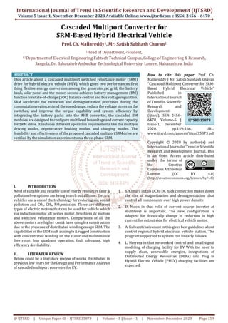
III. Proposed Converter Topology:
Fig 1 Proposed Converter Topology
To achieve the high-efficiency energy conversion among the generator/ac grid, the battery bank, solar panel and the SRM for
HEV applications, a highly integrated multiport converter is proposed with BM function, as shown in Fig. 1.A relay J is used to
connect the generator and the rectifier; a plug is used to connect the ac grid, and three BM modules. It looks like that the
generator/ac plug, solar panels the ac/dc rectifier, the BM modules, and the AHB converter in series. Hence, the proposed
converter can be containing as the combination of a front-end circuit and an AHB converter. The generator can act as a starter
motor, as well as be used to charge the battery bank and power the SRM. The battery bank can also be charged by the SRM,
solar PV power and the ac grid. The SRM can be powered by the battery bank orderly or overly. For separately managed and
composed of a battery pack and three power switches with anti-parallel diode which help to improve the flexibility and
reliability of the battery packs, more BM modules can be designed. By using the proposed topology, number of driving modes,
regenerative braking modes, and charging modes are achieved to satisfy different operation conditions.
IV. Control Strategies of the Proposed Converter
4.1. CONTROL STRATEGY UNDER DRIVING MODES
There are two control strategies are used in the SRM drive system via including current chopping control (CCC) and voltage-
PWM control (VPC). Fig. 2 presents a block diagram of SRM control system. A position encode is helped to detect the rotor
position for commutation control and speed calculation. A proportional integral (PI) controller is employed for speed closed-
loop control. The control mode switch is used to select the control strategies according tospeedreference.Thedrivingmodeis
employed to driving the motor. Under driving mode, the CCC and VPC control strategies are chosen according to the motor
speed.
Fig 2 Control strategy under driving modes
4.2. CONTROL STRATEGY UNDER REGENERATIVE BRAKING MODES
The SRM control system is analyzed by Fig. 3, when the motor is under the regenerative braking mode. To avoid the over
current damage and implement the pulsed charging process, the CCC is employed to regulate the phase current. According to
braking operation, the different braking current can be set for the inertial braking, slow braking, and quick braking. However,
the energy stored in the phase windings can be used to charge the battery packs.
3. International Journal of Trend in Scientific Research and Development (IJTSRD) @ www.ijtsrd.com eISSN: 2456-6470
@ IJTSRD | Unique Paper ID – IJTSRD35873 | Volume – 5 | Issue – 1 | November-December 2020 Page 161
Fig 3 Control strategy under regenerative braking modes
4.3. CONTROL STRATEGY UNDER CHARGING MODES
The proposed converter can act as a charger to charge the batteries. The charging process can be arranged into three steps
according to the SOC, as shown in Fig. 4.
In step 1-(0<SOC<SOC1) which means that the battery pack isunderextremeenergylosscondition.Toprotectthe batteryfrom
vital damage, the pre-charge stage is necessary and a lower constant-current (i.e. iref1) charging mode is employed to protect
the battery packs.
In step 2-(SOC1<SOC<SOC2) a standard constant-current (i.e. iref2) charging mode is employed.
In step3- (SOC2< SOC < 100%) to assurance the battery pack are fully charged, a constant-voltage charging mode is adopted.
Fig 4 Control strategy under charging modes
4.4. SOC BALANCE CONTROL
Hence, the SOC difference among the three battery packs may be caused for the proposed converter topology,accordingtothe
operation conditions, the optimal voltage level will be achieved to power the motor. To protecting the batterypacksfromover
discharge issue, the SOC balance control is important under driving modes as well as to protect the battery packs from the
overcharge issue. The SOC balance control is also necessary under regenerative braking and standstill charging modes.
4. International Journal of Trend in Scientific Research and Development (IJTSRD) @ www.ijtsrd.com eISSN: 2456-6470
@ IJTSRD | Unique Paper ID – IJTSRD35873 | Volume – 5 | Issue – 1 | November-December 2020 Page 162
Fig 5 SOC balance control strategy
V. Simulation Circuit Diagram
Most power full tool for analysis of converter topology MATLAB 2015 is employed. It takes time while compile because of lots
of switching operation done through software its demerits of simulation.
Fig 6 MATLAB simulation diagram
5. International Journal of Trend in Scientific Research and Development (IJTSRD) @ www.ijtsrd.com eISSN: 2456-6470
@ IJTSRD | Unique Paper ID – IJTSRD35873 | Volume – 5 | Issue – 1 | November-December 2020 Page 163
5.1. Outputs of Simulations
Fig.7Solar IV curve
Fig.8 Solar PV curve
Fig. 9 Motor speed curve
6. International Journal of Trend in Scientific Research and Development (IJTSRD) @ www.ijtsrd.com eISSN: 2456-6470
@ IJTSRD | Unique Paper ID – IJTSRD35873 | Volume – 5 | Issue – 1 | November-December 2020 Page 164
Fig.10 Battery discharging curve
Fig11Battery charging curve
Vabc 13, Vabc7, Vabc3 SOC charging discharging curve SOC>80 then discharge n <80 charging mode select asone batteryfully
charged then other will start too charged. Charged battery will go in discharge mode. Scopen rpm will show motor speed
7. International Journal of Trend in Scientific Research and Development (IJTSRD) @ www.ijtsrd.com eISSN: 2456-6470
@ IJTSRD | Unique Paper ID – IJTSRD35873 | Volume – 5 | Issue – 1 | November-December 2020 Page 165
Fig 12 Regenerative brake applied n rpm scope
Fig 13 Motor phase voltage
Fig 14 Torque when regenerative brake applied
8. International Journal of Trend in Scientific Research and Development (IJTSRD) @ www.ijtsrd.com eISSN: 2456-6470
@ IJTSRD | Unique Paper ID – IJTSRD35873 | Volume – 5 | Issue – 1 | November-December 2020 Page 166
Fig 15Pulse to gate for charging batteries with mppt 50% duty cycle
VI. Conclusion
In this study, a cascaded multiport converter is proposedfor
the SRM-based HEV. By adopting the battery packs into the
AHB converter, the reliable energy conversion is achieved
among the generator/ac grid, solar panel, the battery packs,
and the motor. Number of driving modes, regenerative
braking modes, and charging modes can be flexibly selected
in the proposed integrated converter topology. The
converter has the capability of providing the demanded
power by load in absence of one or two resources. The
promising performance of the converter and employed
control method offer a high reliability for utilizing the
converter in industrial and domestic applications
Acknowledgement
This research was supported by FTCR, Sangola, and
Maharashtra.we thankful to our project guide Prof.
Mallaready Chinala, HoD (EE) FTCR, Sangola for great moral
support. We thank our colleagues from Fabtech college of
Engg. Sangola, solapur who provided insight and expertise
that greatly assisted the research.
REFERENCES
[1] S. Kimura, Y. Itoh, W. Martinez, M. Yamamoto, and J.
Imaoka, “Downsizing effects of integrated magnetic
components in high power density DC/DCconverters
for EV and HEV applications,” IEEE Trans. Ind. Appl.,
vol. 52, no. 4, pp. 3294-3305, 2016.
[2] D. Moon, J. Park, and S. Choi, “New interleaved
current-fed resonant converter with significantly
reduced high current side output filter for EV and
HEV applications,” IEEE Trans. Power Electron., vol.
30, no. 8, pp. 4264-4271, Aug. 2015.
[3] A. Kulvanitchaiyanunt, V. C. P. Chen, J. Rosenberger,P.
Sarikprueck, and W. J. Lee, “A linear program for
system-level control of regional PHEV charging
Stations,” IEEE Trans. Ind. Appl., vol. 52, no. 3, pp.
2046-2052, May./Jun. 2016.
[4] L. Herrera, E. Inoa, F. Guo, J. Wang, and H. N. Tang,
“Small-signal modeling and networked control of a
PHEV charging facility,” IEEE Trans. Ind. Appl., vol.50,
no. 2, pp. 1121-1130, Mar./Apr. 2014.
[5] D. Li, R. Qu, J. Li, L. Xiao, L. Wu, and W. Xu, “Analysis of
torque capability and quality in vernier permanent-
magnet machines,” IEEE Trans. Ind. Appl., vol. 52, pp.
125-135, Jan./Feb. 2016.
[6] J. J. Justo, F. Mwasilu, E. K. Kim, J. Kim, H. H. Choi, andJ.
W. Jung, “Fuzzy model predictive direct torque
control of IPMSMs for electric vehicle applications,”
IEEE/ASME Trans. Mechatronics, vol. 22, no. 4, pp.
1542-1553, 2017.
[7] T. A. Huynh and M. F. Hsieh, “Comparative study of
PM-assisted SynRM and IPMSM on constant power
speed range for EV applications,” IEEE Trans. Magn.,
vol. 53, no. 11, Nov. 2017.