(RIA) Call Girls Bhosari ( 7001035870 ) HI-Fi Pune Escorts Service
Unit 2.doc
1. UNIT - II
ELECTRICAL MECHANICS
2.1 DC GENERATOR
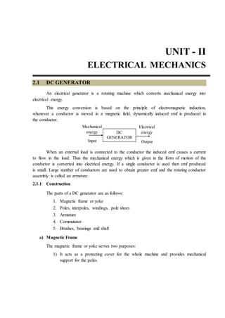
An electrical generator is a rotating machine which converts mechanical energy into
electrical energy.
This energy conversion is based on the principle of electromagnetic induction,
whenever a conductor is moved in a magnetic field, dynamically induced emf is produced in
the conductor.
When an external load is connected to the conductor the induced emf causes a current
to flow in the load. Thus the mechanical energy which is given in the form of motion of the
conductor is converted into electrical energy. If a single conductor is used then emf produced
is small. Large number of conductors are used to obtain greater emf and the rotating conductor
assembly is called an armature.
2.1.1 Construction
The parts of a DC generator are as follows:
1. Magnetic frame or yoke
2. Poles, interpoles, windings, pole shoes
3. Armature
4. Commutator
5. Brushes, bearings and shaft
a) Magnetic Frame
The magnetic frame or yoke serves two purposes:
1) It acts as a protecting cover for the whole machine and provides mechanical
support for the poles.
Output
Electrical
energy
Input
Mechanical
energy DC
GENERATOR
2. 2.2 Basic Electrical and Electronics Engineering
2) It carries the magnetic flux produced by the poles. The flux per pole divides at
the yoke so that the yoke carries only half the flux produced by each pole.
In small machines, the Yoke is made up of cast iron. But for large machines where weight
is the main consideration, cast steel or rolled steel is used.
b) Poles
The poles consists of (i) Pole cores (ii) Pole shoes and (iii) Pole coils. The pole cores
and pole shoes form the field magnet. The end of the Pole Core towards the armature is often
expanded in the form of shoe to reduce the reluctance of the airgap since the cross section
becomes larger at the bottom. Since the poles are electromagnets a field winding is wound over
the pole core. The pole coils are made up of copper wire or strip. When current is passed
through these coils the pole becomes an electromagnet and starts establishing a magnetic field
in the machine.
Air ducts
Key way
Laminations
Slots
3. Electrical Mechanics 2.3
For very small machines the poles are made up of cast iron. For larger machines cast
steel is used. To minimize eddy current losses, the pole is laminated. Sheet steel laminations
are used for this.
c) Interpoles
In modern dc machines commutating poles or interpoles are provided to improve
commutation. Just like the field winding, the commutating poles also have exciting coils which
are connected in series with the armature. Since they carry full armature current, the coils are
made up of fewer turns of thicker conductor to reduce the resistance.
d) Armature
The armature consists of an armature core and armature windings. The armature core
houses the armature conductors or coils. The armature along with the conductors rotates under
the poles and hence the flux produced by the field magnets is cut by the armature conductors.
When the conductors rotate, they alternately come under the influence of north and
south poles. This causes high hysteresis losses in the armature core. To reduce losses, low
hysteresis steel containing a few percentage of silicon is used in the armature.
When the armature core rotates in the pole flux, eddy currents are also produced in it. If
a solid iron armature is used, an emf is induced in an axial direction and iron being a conductor
would result in large circulating current called eddy current to flow in the core. This produces
unnecessary heat which results in heavy power armature core is laminated. In between
laminations insulation is provided. The laminations are about 0.4mm to 0.5mm thick. The
laminations are often known as stampings. In small machines these stampings are directly
keyed on to the shaft.
In larger machines the stampings are first assembled and then keyed on to the armature
spider and the armature spider is then keyed on to the shaft. By so doing, the amount of
material is reduced and free air can be circulated through the centre of the armature.
The eddy current losses and hysteresis losses produce considerable heat in the armature
and Spacers. Ventilating ducts may be necessary to remove this heat. Sometimes a fan is
provided at one end of the armature for good ventilation. The armature conductors are usually
made up of Copper and are housed in the slots provided in the armature. The slots are
rectangular in shape for large machines and circular for small machines. The conductors are
housed in slots in two layers. The slots are closed by fiber or wooden wedges to prevent the
conductors from flying out due to centrifugal force, when the armature rotates.
4. 2.4 Basic Electrical and Electronics Engineering
Steel binding wires are also wound over the armature surface for additional protection.
The slots are well insulated to avoid any short circuit between the armature and the conductors.
e) Commutator
The commutator converts the alternating emf into unidirectional or direct emf. It is
made up of wedge shaped segments or hard drawn or drop forged copper, insulated from each
other by thin layers of built up mica.
The segments are held together by clamping flanges that pull the segments inward
when the flanges are drawn together by bolts and Cap screws. The flanges are further insulated
from the segments by two rings of built up mica. The armature coil leads are soldered to each
commutator segment by a riser.
f) Brushes and Bearings
The brushes, which are made up of carbon or graphite, collect the current from the
commutator and to convey it to the external load resistance. They are rectangular in shape.
These brushes are housed in brush holders and mounted over brush holder studs. The brush
holder studs are mounted on a brush Yoke or, rocker arm. The brush holder studs are insulated
from the brush yoke by insulation sleeves. Ball bearings are usually employed as they are
seliable for light machines. For heavy duty machines roller bearings are used. The bearings are
packed in hard oil for quiter operation.
2.1.2 Principle of Operation
Let us consider a single turn coil ABCD rotated on a shaft within a uniform magnetic
field of flux density. It is rotated in anticlockwise direction.
5. Electrical Mechanics 2.5
Let ‘l’ be the length and ‘b’ breadth of the coil in metres. When the coil sides AB and
CD are moving parallel to the magnetic field, the flux lines are not being cut and no emf is
induced in the coil. At this position, we assume the angle of rotation ‘Ɵ’ as zero.
This vertical position of the coil is the starting position. According to
Faraday’s law II, the emf induced is proportional to the rate of change of flux linkages,
d
e N
dt
Where ‘N’ is the number of turns, ‘ф’ is the flux and ‘t’ is the time.
As N = 1,
d
e volts
dt
Initially, when the coil is moving parallel to the flux lines, no flux line is cut and hence,
d
0
dt
and e = 0
After time ‘t’ secs, the coil would have rotated through an angle ωt radians in the anti-
clockwise direction. The flux then linking with the coil is BlbcosƟ.
m
d
e B bcos t E sin t
dt
Where, Em = B bω,
Em – Maximum Value of induced emf
B – Flux density.
When = 900, the coil sides are moving at right angles to the flux lines. The flux lines
are cut at the maximum rate and the emf induced is maximum. When =1800, the coil sides
are again moving parallel to the flux lines (AB and CD have exchanged positions) and the emf
induced is zero once again. When = 2700, the coil sides again move at right angles to the
flux lines but with their position reversed when compared with = 900. Hence the induced
emf is maximum in the opposite direction. When = 3600, the coil sides once again move
parallel to the magnetic field making the induced emf equal to zero. The coil has now come
back to the starting point.
If the rotation of the coil is continued, the changes in the emf are again repeated. For
the two pole generator shown one complete cycle of changes occurs in one revolution of the
coil. The changes in Voltage, e with respect to the angle or even time can be plotted.
6. 2.6 Basic Electrical and Electronics Engineering
The emf changes from instant to instant and becomes alternatively positive and
negative. Such an emf is called as alternating emf. If the coil sides are connected to two slip
rings a and b and an external resistance R connected across them, a current flows through the
resistor, which is again alternating.
The induced emf in the coil can be increased by,
1) Increasing the flux density (B) and
2) Increasing the angular veloctiy (ω).
In commercial generators a large number of coils are used and they are housed in the
armature, which rotates on a shaft at high speed.
The current flowing in the external resistance to a DC generator is made unidirectional
by replacing the slip rings by a split rings. The ring is split into two equal segments P and Q
and the segments are insulated from each other and also from the shaft. The coil side AB is
always attached to the segment P and likewise CD to Q. The brushes B1 and B2 touch these
segments and are meant to collect the current.
During the first half revolution, current flows along ABLMCD through brush B1 which
is positive and into B2 (negative brush). After half a cycle AB and CD have exchanged
positions along with the segments P and Q and current now flows, through DCLMBA. B1 is
now in contact with Q (B1 continues to be positive)
For each half revolution, the positions of segments P and Q also reversed. Hence the
current in the load is always unidirectional. The change over of segments P and Q takes place.
7. Electrical Mechanics 2.7
When flux linkage or induced emf is minimum. In a generator, the split rings are called
commutator.
2.2 EMF INDUCED IN A DC GENERATOR
Let ф be the flux per pole in webers.
Let P be the number of poles.
Let Z be the total number of conductors in the armature. All the Z conductors are not
connected in series. They are divided into groups and let A be the number of parallel paths into
which these conductors are grouped. So each parallel path will have Z/A conductors in series.
Let N be the speed of rotation in revolutions per minute (rpm).
Consider one conductor on the periphery of the armature. As this conductor makes one
complete revolution, it cuts Pф webers. As the speed is Nrpm, the time taken for one
revolution is 60/N secs.
Since the emf induced in the conductor = rate of change of flux cut,
0
0 900 1800 2700
3600
e
8. 2.8 Basic Electrical and Electronics Engineering
d p
e
60
dt
N
NP
e volts
60
Since there are Z/A conductors in series in each parallel path, the emf induced,
g
NP Z ZN P
E . volts
60 A 60 A
The armature conductors are generally connected in two different ways, viz lap
winding and wave winding. For lap wound armature, the number of parallel paths is equal to
the number of poles (ie, A = P). In wave wound machines, A = 2 always
Example Problems
Problem 1:
Calculate the emf generated by a b pole DC generator having 480 conductors and
drives at a speed of 1200rpm. The flux per pole is 0.012 wb. Assume the generator to be a) Lap
wound b) Wave wound.
Solution
g
ZN P
E volts
60 A
a) For a lap wound machine, A = P = 6
g
0.012 480 1200 6
E 115.2 volts
60 6
Eg = 115.2 V
b) For a wave wound machine, A = 2
g
0.012 480 1200 6
E 345.6 volts
60 2
Eg = 345.6 V
9. Electrical Mechanics 2.9
Problem 2
A 8 pole, DC generator has a simplex Wave Wound armature containing 32 coils of 6
turns each. Its flux per pole is 0.06 wb. The machine is running at 250 rpm. Calculate the
induced armature voltage.
Given
P = 6, Z = 2 × 32 × 6 = 384, ф = 0.06 wb, A = 2
Solution
Induced armature
Voltage, g
P NZ
E
60A
g
8 0.06 250 384
E 384volts
60 2
Eg = 384 v
Problem 3
A dynamo has a rated armature current of 250A. What is the current per path of the
armature if the armature is simplex wave wound or simplex lap wound? The machine has 12
poles.
Given
Ia = 250 A, P = 12
Solution
For wave woound, A = 2,
a
I 250
I 125A
A 2
I = 125A
For lap wound, A = P
10. 2.10 Basic Electrical and Electronics Engineering
a
I 250
I 20.83A
A 12
I = 20.83A
2.2.1 Applications of DC generators
DC supply has for almost all applications been replaced by alternating current. AC has
the chief advantage that the voltage level can be easily stepped up or down.
However, DC is in use for some special applications and where the DC equipment is
still in operation. Shunt generators are used for supplying nearly constant loads.
They are used for battery charging, for supplying the fields of synchronous machines
and separately excited dc machines.
Since the Output Voltage of a series generator increases with load, series generators are
ideal for use as boosters for adding a Voltage to the transmission line and to compensate for
the line drop.
The series generator is connected in series with the line and operated in the straight line
portion of the characteristic.
Compound generators maintain better Voltage regulation and hence find use where
constancy of Voltage is required eg, for a self contained generator unit.
2.3 DC MOTORS
The DC motor converts electrical energy into mechanical energy. The input to a DC
motor is electrical and the output is mechanical rotation or torque.
The fundamental principles and construction of the DC motors are identical with DC
generators which have the same type of excitation. A DC machine that runs as a motor will
also operate as a generator.
2.3.1 Principle of Operation
The basic principle of operation of dc motor is that “whenever a current carrying
conductor is placed in a magnetic field, it experiences a force tending to move it”.
11. Electrical Mechanics 2.11
(i) Uniform magnetic field only
If a current carrying conductor is placed between two magnetic poles, both the fields
will be distorted.
Magnetic torque causes rotation to spin counter clockwise.
(ii) Current carrying conductor only
(iii) Positive current carrying conductor and magnetic field
(iv) Negative current carrying conductor and magnetic field
Above the conductor, the field is weakened (less flux) and below the conductor, the
field is strengthened. Therefore the conductor tends to move upwards. The force exerted
N S
+
-
T2 Current carrying
conductor flux line
N S
Current carrying
conductors in
magnetic field
+
+
Flux crowding
Current carrying
conductors
without magnetic
field
+
N S
Conductor
without
current
Main field
12. 2.12 Basic Electrical and Electronics Engineering
upwards depends upon the intensity of the main field flux an magnitude of the current. Then
the direction of the current through the conductor is reversed.
Here, the field below the conductor is less (weakend) and field above the conductor is
more (strengthened). Then the conductor tends to move downwards.
(v) Both current carrying conductor and uniform magnetic field
The magnitude of the force experienced by the conductor in a motor is given y,
F = BI Newtons
Where, B = Magnetic field density in Wb/m2
I = Current in amperes
= length of the conductor in metres.
The direction of motion is given by Flemming’s Left hand rule, which states that if the
thumb, fore finger and middle finger of the left hand are held such that the fingers show three
mutually perpendicular directions and if the fore finger indicates direction of the field, and the
middle finger indicates the direction of current, then the thumb points the direction of the
motion of conductor. In a dc motor, a strong electromagnetic field and a large number of
current carrying conductors housed in a armature, make the armature to rotate.
Back EMF
While a machine functions as a motor, the conductors are cutting flux and that is
exactly what is required for generator action, to take place. This means that even when the
machine is working as a motor, voltages are induced in the conductor. This emf is called the
- +
N
T
1
T
2
S
+
13. Electrical Mechanics 2.13
back emf or counter emf, since the cause for this is the rotation, which, in turn, is due to the
supply voltage. According to Lenz’s law, the direction of the back emf oppposes the supply
voltage.
The back emf is given by the same equation for induced emf of a generator as
b
ZN P
E volts
60 A
---- (1)
In the equivalent circuit of a motor, the armature circuit is equivalent to a source of emf
Eb, in series with a resistance of Ra and a DC supply is applied across these two. The voltage
equation of this DC motor is,
V = Eb + Ia Ra volts ---- (2)
From this equation, armature current is
b
a
a
V E
I Amps
R
---- (3)
Where, V – applied Voltage,
Eb – Back Emf,
Ia – Armature current,
Ra – Armature Resistance.
V-Eb – Net voltage in the armature circuit.
From the equations (1) & (2), the induced emf in the armature of a motor Eb depends
upon armature speed and armature current Ia depends upon the back emf Eb for a constant input
voltage V and the armature resistance Ra. If the motor speed is high, back emf Eb is large and
V
+
Ra
+
Ia
14. 2.14 Basic Electrical and Electronics Engineering
therefore armature current is small. If the motor speed is low, then back emf Eb will be less and
armature current is more.
Voltage Equation of DC motor
From the figure,
V – Input voltage
Eb – Back emf
Ra – Armature Resistance
Ia – Armature current
Ish – Shunt field current,
Rsh – Shunt field resistance.
Line current, IL = Ia + Ish
Here, the current flowing in the armature is given by,
b
a
a
V E
I
R
or V = Eb + Ia Ra
This equation is known as voltage equation of a DC motor.
Power Relationship of DC motor
The voltage equation is, V = Eb + Ia Ra
Multiplying each term of the voltage equation by Ia,
VIa = EbIa + Ia
2 Ra
This equation is known as power equation of a DC motor.
VIa – Electric power supplied to armature (input to the armature)
EbIa – Power developed by the motor armature (Output of the armature i.e,
mechanical output)
Ia
2Ra – Power loss in the armature (armature copper loss).
15. Electrical Mechanics 2.15
Applications of DC motors
DC shunt motors are used where the speed has to remain nearly constant with load and
where a high starting torque is not required.
These shunt motors may be used for driving centrifugal pumps and light machine tools,
wood working machines, lathes etc.
Series motors are used where the load is directly attached to the shaft or through a gear
arrangement and where there is no danger of load being “thrown off”.
Series motors are ideal for use in electric trains, where the self-weight of the train acts
as load and for cranes, hoists, fans, blowers, conveyors, lifts, etc. Where the starting torque
requirement is high.
Compound motors are used for driving heavy machine tools for intermittent loads
shears, punching machines etc.
2.4 TRANSFORMERS
Transformer works on the principle of electromagnetic induction. A transformer is an
electrical device, having no moving parts, which by mutual induction transfers electric energey
from one circuit to another at the same frequency, usually with changed values of voltage and
current. It consists of two windings insulated from each other and wound on a common core
made up of magnetic material.
Alternating voltage is connected across on of the windings called the primary winding.
In both the windings emf is induced by electromagnetic induction. The second winding is
called secondary winding.
Primary
Winding
Secondary
Winding
N1 N2
AC
Supply V1 V2
16. 2.16 Basic Electrical and Electronics Engineering
2.4.1 Working Principle of a Transformer
When the primary winding is connected to an AC source an exciting current flow
through the winding. As the current is alternating, it will produce an alternating flux in the core
which will be linked by both the primary and secondary windings. The induced emf in the
primary winding (E1) is almost equal to the applied voltage V1 and will oppose the applied
voltage. The emf induced in the secondary winding (E2) can be utilized to deliver power to any
load connected across the secondary. Thus, power is transferred from the primary to the
secondary circuit by electromagnetic induction.
The flux in the core will alternate at the same frequency as the frequency of the supply
voltage. The frequency of induced emf in the secondary is the same as that of the supply
voltage. The magnitude of the emf induced in the secondary winding will depend upon its
number of turns.
In a transformer, if the number of turns in the secondary winding is less than that in the
primary winding, it is called a step-down transformer. When the number of turns in the
secondary winding is higher than the primary winding it is called a step-up transformer.
2.4.2 Classifications of Transformers
Transformers are classified on the basis of
i) Duty, they perform
1. Power transformer – for transmission and distribution purposes.
2. Current transformer – instrument transformer
3. Potential transformer – instrument transformer
ii) Construction
1. Core type transformer
2. Shell type transformer
Secondary
Primary
Step up transformer
Secondary
Primary
Step down transformer
17. Electrical Mechanics 2.17
3. Berry type transformer
iii) Voltage Output
1. Step down transformer (Higher to Lower)
2. Step Up transformer (Lower to Higher)
3. Auto transformer (Variable to‘0’to rated value)
iv) Application
1. Welding Transformer
2. Furnace Transformer
v) Cooling
1. Duct type transformer (Air natural or Air blast)
2. Oil immersed
a. Self cooled
b. Forced air cooled
c. Water cooled
d. Forced oil cooled
vi) Input supply
1. Single phase transformer
2. Three phase transformer
a. Star – Star
b. Star – Delta
c. Delta – Delta
d. Delta – Star
e. Open – Delta
f. Scott connection
18. 2.18 Basic Electrical and Electronics Engineering
2.4.3 Construction Details
A transformer is a static device and its construction is simple as there are no moving
parts.
The main components of a transformer are
i) The magnetic core
ii) Primary and Secondary windings
iii) Insulation of windings
iv) Expansion tank or conservator
v) Lead and tappings for coils with their supports, terminals and terminal
insulators.
vi) Tank, oil, cooling arrangement, temperature guage, oil guage.
vii) Buchholz relay
viii) Silica gel breather
Magnetic core
Magnetic circuit consists of an iron core. The transformer core is generally laminated
and is made out of a good magnetic material like silicon steel. The thickness of laminations or
stampings varies from 0.35mm to 0.5mm. The laminations are insulated from each other by
coating then with a thin coat of varnish.
Various types of stampings and laminations employed in the construction of
transformers. The joints are staggered to avoid continuous gap causing increase in magnetizing
current. If the joints are not staggered, the core will have less mechanical strength and during
operation there would be undue humming noise. After arranging the laminations, they are
bolted together.
First set of stamping Second set of stamping Finished core
19. Electrical Mechanics 2.19
The two types of transformer cores are
a. Core type
b. Shell type
Core type transformer
Here the windings surround a considerable part of core. It has only one magnetic path.
It has two limbs for the two windings and is made up of two L-type stampings. The coils used
usually are of cylinderical type and are usually wound. For transformers of higher rating
stepped core with core of square or rectangular cross section is used. Insulating cylinders are
used to separate windings from the core and from each other.
Shell type transformer
Here the core surrounds the considerable part of windings. The two windings are
carried by central limb. The core is made up of E and I stampings and has threee limbs. It has
two parallel paths for magnetic flux.
The coils used are of multilayer disc type and are former wound in the form of pan-
cakes. Each layer is insulated from each other by paper.
(a)
(b)
20. 2.20 Basic Electrical and Electronics Engineering
Windings
There are two windings in a transformer. They are called primary and secondary
windings. Generally the windings are made up of copper.
Insulation
Paper is still used as the basic conductor insulation. Enamel insulation is used as the
inter-turn insulation for low voltage transformer. For power transformer enameled copper with
paper insulation is also used.
Insulating oil
The oil used in transformer protects the paper from dirt and moisture and removes the
heat produced in the core and coils. It also acts as insulating medium. The oil must possess the
following properties
i) High dielectric strength
ii) Free from inorganic acid, alkali and corrosive sulphur to prevent injury to the
conductor or insulation.
iii) Low viscosity to produce good heat transfer.
iv) Free from sludging under normal operating conditions.
v) Good resistance to emulsion so that the oil may throw down any moisture entering the
tank instead of holding it in suspense.
Expansion tank or conservator
A small auxiliary oil tank may be mounted above the transformer and connected to
main tank by a pipe. Its function is to keep the transformer tank full of oil despite expansion or
contraction of the coil with the changes in temperature. A small pipe connection between the
gas space in the expansion tank, and the cover of the transformer tank permits the gas above
the oil in the transformer to pass into the expansion tank, so that the transformer tank will be
completely filled with oil.
Temperature Gauge
Every transformer is provided with a temperature gauge to indicate hot oil or hottest
Spot temperature. It is self-contained weather-proof unit made of alarm contacts. It is dial
operated by bourdon gauge connected to a thermometer bulb located in the region of hottest
oil.
21. Electrical Mechanics 2.21
Oil Gauge
Every transformer is fitted with an oil gauge to indicate the oil level present inside the
tank. The oil gauge may be provided with an alarm contact which gives an alarm when the oil
level has dropped beyond permissible height due to oil leak or due to any other reason.
Buchholz Relay
The first warning that a fault is present may be given by the presence of bubbles in the
oil. If the transformer is fitted with a conservator and there are no pockets in which gas can
collect, the gas bubbles will rise up the pipe joining the conservator to the tank. It is possible to
mount gas operated relay in this pipe to give an alarm in case of minor fault and to disconnect
the transformer from the supply mains in case of severe faults.
Breather
The simplest method to prevent the entry of the moisture inside the transformer tank is
to provide chambers known as breather. The breather is filled with some drying agent, such as
calcium chloride or silica gel. Silica gel or calcium chloride absorbs moisture and allows dry
air to enter the transformer tank. The drying agent is replaced periodically as routine
maintenance. The whole of the transformer tank and portion of conservator used is filled with
oil. The breather is connected on one side of the conservator. Thus a small surface area of
transformer oil is exposed to the atmosphere through the breather.
Bushings
Connections from the transformer windings are brought out by means of bushing.
Ordinary porcelain insulators can be used upto a Voltage of 33KV. Above 33KV, Capacitor
and oil filled type of bushings are used. Bushings are fixed on the transformer tank.
Transformer tank
Transformer oil
Buccholz relay
Conservator
tank
Breather
Silica gel
Winding
22. 2.22 Basic Electrical and Electronics Engineering
2.4.4 EMF Equation of a Transformer
Consider a transformer arrangement as follows:
N1 – Number of primary turns
N2 – Number of secondary turns
Фm – Maximum Value of flux in the core in Wb
Bm – Maximum Value of flux density in the core in Wb/m2
A - Area of the core in m2
f – Frequency of the AC supply in Hertz
V1 – Supply Voltage across primary in Volts
V2 – Terminal Voltage across secondary in Volts
I1 – Full load primary current in amperes
I2 – Full load secondary current in amperes
E1 – Emf induced in the primary in Volts
E2 – Emf induced in the secondary in Volts
Since applied Voltage is alternating in nature, the flux established is also an alternating
one. The flux will attain its maximum Value in one quarter of the cycle.
We know that T = 1/f, Where ‘f’ is the frequency in Hertz.
If we assume single turn coil, then according to Faradays laws of electromagnetic
induction, the average Value of emf induced / turn = 4f × фm Volts.
N1
E1
V1
AC
supply
N2
E2
V2
Load
I1 I2
23. Electrical Mechanics 2.23
RMS value
Form factor 1.11
Average value
(since m
is sinusoidal)
RMS Value = Form factor × Average value
RMS Value of emf induced / turn = (1.11) (4fфm) = 4.44fфm Volts
RMS value of emf induced in the entire primary winding,
E1 = 4.44fфm × N1
E1 = 4.44fBmAN1 Volts
Similarly RMS Value of emf induced in the secondary,
Ed = 4.44fфmNd Volts.
(or) E2 = 4.44fBmAN2 Volts
Transformation Ratio (K)
For an ideal transformer,
V1 = E1, V2 = E2, V1 I1 = V2 I2
2 1 2 1
1 2 1 2
V I E I
,
V I E I
2 2 2 2 1
1 1 1 1 2
E N E N I
, k
E N E N I
Where ‘K’ is called transformation ratio.
max
Flux
T
Time
0
T/4
T/2
2
24. 2.24 Basic Electrical and Electronics Engineering
Note
If N2 > N1 ie K > 1, then transformer is a step up transformer. If N2 < N1, ie K < 1, then
transformer is a step down transformer.
Voltage ratio = 2
1
E
E
= K
Current ratio = 2
1
I
I
=
1
K
Example Problems
Problem 1
The no load ratio required in a single phase 50 Hz transformer is 6600 / 300 V. If the
maximum Value of flux in the core is to be about 0.09 weber, Find the no/. of turns in each
winding.
Given data
Supply frequency f = 50Hz, Primary Voltage, V1 = 6600 V
Secondary Voltage V2 = 300V, Maximum Value of flux фm = 0.09 wb
To find
The no/. of turns in primary & secondary windings (N1 and N2)
Solution
The primary and secondary turns can be found out from the emf equation of a
transformer.
V1 = E1 = 4.44fфmN1 ----- (1)
V2 = E2 = 4.44fфmN2 ----- (2)
From equation (1)
Primary turns, N1 =
1
m
V
4.44f
6600
330turns
4.44 50 0.09
25. Electrical Mechanics 2.25
From equation (2)
Secondary turns, N2 = 2
m
V
4.44f
300
15turns
4.44 50 0.09
Problem 2
The primary and secondary voltages of a 25KVA power transformer are 2200V and
220V respectively. The transformer has 56 turns in the secondary. Calculate the number of
turns in the secondary. Calculate the number of turns in the primary.
Given
V1 = 2200, V2 = 220V, N2 = 56
Solution
By using transformation ratio, K.
2 2
1 1
V N
V N
2
1 2
1
V
N N
V
2200
56 560
220
N1 = 560 turns
Problem 3
A sinusoidal flux 0.02 Wb links with 55 turns of a transformer secondary coil.
Calculate the rms value of the induced emf in the secondary. The supply frequency is
50 Hz.
Given data
Ф = 0.02Wb, N2 = 55, f = 50 Hz,
Maximum Value = 2 × RMS Value
26. 2.26 Basic Electrical and Electronics Engineering
Maximum flux, фm = 2 × RMS value of flux (ф)
= 2 × 0.02 = 0.028 Wb
Solution
RMS Value of induced emf in the secondary (E2)
E2 = 4.44f фm N2 = 4.44 × 50 × 0.028 × 55
E2 = 341.8 V
Applications of Transformer
Transformers are used in:
1. Electrical power Engineering for transmission and distribution.
2. As an instrument transformer for measuring current (CT) and measuring Voltage
(PT)
3. As a step down and step up transformer to get reduced or increased output voltage.
4. Radio and TV circuits, telephone circuits, control and instrumentation circuits.
5. Furnaces and welding transformer.
2.5 INTRODUCTION – SINGLE PHASE INDUCTION MOTOR
The main disadvantage of single-phase motors is:
1. Lack of starting torque
2. Reduced power factor
3. Low efficiency
a) Single Phase Induction Motor
The majority of single-phase motors are of induction type. The power rating is in terms
of fractional horse power. They are classified according to the starting methods,
employed.
27. Electrical Mechanics 2.27
They are,
1. Resistance – Start (Split-phase)
2. Capacitor run
3. Capacitor start
4. Shaded pole
b) Construction of Single-Phase Induction Motor
The construction of a single-phase induction motor is similar to three phase cage
induction motor. The rotor is the same as that of a three-phase induction motor but the
stator has only a single-phase distributed winding. It consists of two parts. One is stator
and another one is rotor. The air gap between stator and rotor is uniform. There is no
external connection between stator and rotor.
Single Phase Induction Motor
From the principle of operation, the ф induction motor has no self-starting torque.
c) Operation of Single-Phase Induction Motor
The stator winding of a single-phase induction motor is connected to single phase AC
supply. Then a magnetic field is developed in the stator whose axis is always along the
axis of stator windings. With alternating current in the fixed stator coil the mmf wave is
stationary in space but pulsates in magnitude and varies sinusoidally with time.
Due to the transformer action, currents are induced in the rotor conductors. The
direction of the current is to oppose the stator mmf.
Thus, the axis of rotor mmf wave coincides with the axis of stator mmf wave.
Therefore, the torque angle is Zero and no starting torque is developed in the motor.
However, if rotor is initially given a starting torque by means, the motor will pick up
the speed and continue to rotate in the same direction. Thus, the single-phase induction
motor is not a self-starting motor. The starting torque can be produced by some
external arrangement.
d) Starting of Single-Phase Induction Motor
28. 2.28 Basic Electrical and Electronics Engineering
The starting method of single-phase induction motor is very simple. An auxiliary
winding in the stator is provided in addition to the main winding. Then the induction
motor starts as a two-phase motor.
The main winding axis and auxiliary winding axis are displaced by 90 electrical
degrees. The impedances of the windings differ and currents in the main and auxiliary
windings are phase shifted from each other. As a result of this, a rotating stator field is
produced and the rotor rotates.
When the motor speed is about 75% of synchronous speed, the auxiliary winding is
disconnected from the circuit. This is done by connecting a centrifugal switch in the
auxiliary winding which is used for starting purpose only. That is why it is called
starting winding. That is why it is called running winding.
e) Types of Single-Phase Induction Motor
The single-phase induction motors can be classified according to the phase difference
produced between the currents in the main and auxiliary winding. The classifications
are:
1. Split – Phase motors
2. Capacitor – Start motors
3. Capacitor – run motors
4. Capacitor – Start and run motors
5. Shaded – Pole motors
1. Split – Phase motors
Auxiliary
winding
Main
winding
ROTOR
29. Electrical Mechanics 2.29
It consists of two stator windings. One is the main winding or running winding and
another is auxiliary winding or stator winding. These two winding axes are displaced
by 90 electrical degrees. The auxiliary winding has high resistance and low reactance
and main winding has low resistance and high reactance. Ir is the current flowing
through the running winding and Is is the current flowing through the starting. These
two currents are out of phase. The auxiliary winding is used only for starting period.
The auxiliary winding is used only for starting period. When the motor speed is about
75% of synchronous speed, the auxiliary winding is disconnected from the circuit. This
is done by connecting a centrifugal switch in the auxillary circuit. After this, motor runs
because of main winding only.
In the Speed – torque characteriestics of Split – phase induction motor it shows that
upto 75% of speed, main and auxiliary windings are present in the circuit and after 75%
of the speed is attained, only the main winding is present in the circuit. The starting
torque of the motor can be increased by connecting a resistance in series with the
auxiliary winding. Split phase induction motor is also called resistance start induction
motor.
It is mainly used for loads that require low or medium starting torque. The applications
are:
1. Fans
2. Blowers
3. Centrifugal pumps
4. Washing machines
The characteristics of this motors are:
1. The starting torque is 100% to 250% of the rated value.
2. The breakdown torque is upto 300%
3. The power factor of this motor is 0.5 to 0.65
4. The efficiency of the motor is 55% to 65%
5. The power rating of this motor is in the range of ½ to 1 HP
2. Capacitor Start Single Phase Induction Motor
30. 2.30 Basic Electrical and Electronics Engineering
It is one type of single-phase induction motor. Here, a capacitor is connected in series
with the auxiliary winding. It is also used to get higher starting torque. Single – Phase
supply is applied to the two windings. The starting current Is leading the line voltage,
because of the capacitor present in the auxiliary winding. The running current Ir lags the
line voltage. The phase displacement between the two currents is approximately equal
to 900 during starting.
Again the auxiliary winding is disconnected from the circuit by centrifugal switch at
75% of the synchronous speed, ie. the capacitor is used during starting period only. The
direction of rotation of the motor can be changed by changing the connections of one of
the windings.
It is mainly used for hard starting loads, such as
1. Compressors
2. Pumps
Main
winding
Auxiliary
winding
Ia
Im
Cage
Rotor
V
Centrifugal
switch
Ia
I
C
m
Ia
Im
I
V
31. Electrical Mechanics 2.31
3. Conveyors
4. Refrigerators
5. Air conditioning equipments
6. Washing machines
Characteristics of these motors are:
1. The starting torque is 250% to 400% of the rated value.
2. The breakdown torque is upto 350%
3. Power factor of the motor is 0.5 to 0.65
4. The power rating of the motor is 1/8 to 1 HP.
5. The efficiency of the motor is 55% to 65%.
3. Capacitor – Run Motor
In this motor, a capacitor is permanently connected in series with the auxiliary winding.
Here, the centrifugal switch is not needed and therefore the cost of the motor is less.
The capacitor value is in the range of 20.50 µF. The capacitor is AC paper oil type. The
starting torque has to be sacrificed because the capacitor chosen is a comprimise
between the best starting and running conditions.
Advantages
1. High power factor at full-load
2. High full load efficiency
50
100
150
200
0
20 40 60 80 100
Percent of synchronous Speed
Percent
of
torque
Main
winding
Auxiliary
winding
Ir
Cage
Rotor
V
Ia
I
C
32. 2.32 Basic Electrical and Electronics Engineering
3. Increased pull-out torque
4. Low-full load line current.
Applications
1. Fans
2. Blowers
3. Centrifugal pumps
Characteristics
1. The starting torque is 100% to 200% of rated value.
2. The breakdown torque is upto 250%
3. The power factor of the motor is in the range of 0.75 to 0.9
4. The efficiency of the motor is 60 to 70%
5. The power rating of the motor is 1/8 to 1 HP.
4. Capacitor – Start Capacitor – run Motor
Here two capacitors are used. One capacitor Cs is used for starting purpose and those
another capacitor Cr is used for running purpose. In this motor, we can get high starting
torque, because of two capacitors.
The value of starting capacitor Cs is large and the value of running capacitor Cr is
small. The running capacitor Cr is permanently connected in series with auxiliary
Main
winding
Ir
Rotor
V
Is
Cs
Cr
Centrifugal
switch
33. Electrical Mechanics 2.33
winding. When the motor speed picks upto 75% of synchronous speed, the centrifugal
switch is opened and the starting capacitor Cs is disconnected from the circuit.
The capacitor Cs is used for developing high starting torque and capacitor Cr is used to
improve the power factor.
Advantages
1. High starting torque
2. High efficiency
3. High power factor
They are mainly used for low noise and high starting torque applications such as
1. Compressors
2. Pumps
3. Conveyors
4. Refrigerators
Characteristics
1. The starting torque is 200% to 300% of rated value.
2. The rated breakdown torque is upto 250%
3. The power factor of the motor is in the range of 0.75 to 0.9
100
200
300
0
20 40 60 80 100
Main
winding
Percent
of
torque
Percent synchronous Speed
Main and
auxiliary
winding
34. 2.34 Basic Electrical and Electronics Engineering
4. The efficiency of the motor is 60 to 70%
5. The power rating of the motor is 1/8 to 1 HP.
5. Shaded Pole Motor
Construction
Shaded pole motor is a split phase type single phase induction motor. It has salient
poles on the stator excited by single phase supply and a squirrel cage rotor. A position
of each pole is surrounded by a short-circuited turns of copper strip called shading coil.
It has no commutator, brushes, collector rings, contactors, capacitors or moving switch
parts and so it is relatively cheaper, simpler and extremely rugged in construction and
reliable.
Operation
The operation of the motor can be understood by referring the above figure which
shows one pole of the motor with a shading coil.
1. During the portion OA of the alternating current cycle the flux begins to
increase and an emf is induced in the shading coil. The resulting current in the
shading coil will be in such a direction as to oppose the change in flux. Thus the
flux in the shaded portion of the pole is weakened while that in the unshaded
portion is strengthened.
2. During the portion AB of the alternating current cycle, the flux has reached
almost maximum value and is not changing. Consequently, the flux distribution
across the pole is uniform since no current is flowing in the shading coil.
35. Electrical Mechanics 2.35
3. As the flux decreases ie. portion BC of the alternating current cycle, current is
induced in the shading coil so as to oppose the decrease in current. Thus the
flux in the shaded portion of the pole is strengthened while that in the unshaded
portion is weakened.
The effect of the shading coil is to cause the field flux so shift across the pole face from
the unshaded to the shaded portion. This shifting of flux is like a rotating weak field
moving in the direction from unshaded portion of the shaded portion of the pole.
The rotor is of squirrel cage type and is under the influence of this moving field.
Consequently a small starting torque is developed. As soon as this torque starts to
36. 2.36 Basic Electrical and Electronics Engineering
resolve the rotor, additional torque is produced by single phase induction motor action.
The motor accelerates to a speed slightly below the synchronous speed and runs as a
single phase induction motor.
The main advantages of these motors are:
1. Low efficiency
2. Low power factor
3. Very low starting torque
The main applications of these motors are for loads requiring low starting torque such
as:
1. Fans
2. Blowers
3. Turn tables
4. Hair driers
5. Motion picture projectors
The characteristics of these motors are
1. The starting torque is 40% to 60%
2. The breakdown torque is upto 140%
3. The power factor of the motor is in the range of 0.25 to 0.4
4. The efficiency of the motor is 25% to 40%
5. The power rating of the motor ranges upto 40W.
37. Electrical Mechanics 2.37
REVIEW QUESTIONS
1. What is back emf?
2. Why a dc series motor cannot be started on no load?
3. What are the various types of dc motors?
4. What is the necessity of a starter for a dc motor?
5. What is torque?
6. What is speed regulation?
7. What is called armature torque?
8. What is called shaft torque?
9. Draw the characteristics curve of a dc shunt motor?
10. What is the difference between three point and four point starters?
11. What is the method available for testing dc series motor?
12. Name the protective devices used in a 3point starter?
13. Mention the methods of speed control for a dc motor?
14. What are the losses that occur in a dc motor?
15. What are the various types of dc generators?
16. Draw the internal and external characteristic curves of dc shunt generator?
17. Draw the internal and external characteristic curves of dc series generator?
18. Draw the characteristics curves of dc compound generator?
19. What is the function of commutator in DC generator?
20. What is the function of carbon brushes in DC generator?
21. What is called voltage regulation?
22. Write short notes on efficiency of a DC motor?
23. How the voltage builds up in Dc generator?
24. Why the armature core is made by laminated sheets?
38. 2.38 Basic Electrical and Electronics Engineering
25. Explain the construction and working principle of D.C generator with neat diagram. (16)
26. Explain the different types of D.C generators. (16)
27. Draw and explain the characteristics of different types of d.c generators. (16)
28. Derive the emf equation of D.C. Generator. (8)
29. Sketch and explain the speed-current, speed-torque and torque-current characteristics of a
shunt motor, series motor and compound motor. (16)
30. Draw the characteristic curves of D.C. shunt, series and compound motors. Use these curves
to explain the applications for which these motors are used. (16)
31. List all the important parts of a D.C. Motor and explain the importance of each
32. Calculate the emf generated by 4 pole wave wound generator having 65 slots with 12
conductors per slot when driven at 1200 rpm. The flux per pole is 0.02 wb. (8)
33. A 4 pole lap wound dc shunt generator has a useful flux per pole of 0.07wb. The armature
winding consists of 220 turns, each of 0.004 ohm resistance. Calculate the terminal voltage
when running at 900 rpm if the armature current is 50A. (16)
34. Explain the principle of working a transformer?
35. Discuss the difference between core type and shell type construction?
36. Draw the no load phasor diagram of a transformer?
37. Draw the phasor diagram of a transformer under load condition?
38. Explain voltage regulation?
39. Derive the emf equation of a transformer?
40. What is meant transformation ratio?
41. How the transformers are classified?
42. Derive the condition for maximum efficiency?
43. What are the various losses that must be present in a transformer?
44. Explain the construction and working principle of single-phase transformer.(16)
45. Enumerate the various types of transformer. (4)
46. Draw and explain the no load phasor diagram for a single-phase transformer. (6)
39. Electrical Mechanics 2.39
47. What is KVA rating of a transformer? (8)
48. The no load current of a transformer is 10A at a power factor of 0.25 lagging, when
connected to 400v,50Hz supply, calculate(i)magnetizing component of no load current(ii)
iron loss and(iii) maximum value of the flux in the core. Assume primary winding turns as
500. (8)
49. What is the frequency of induced emf of an induction motor?
50. Why squirrel cage induction motors are common in the domestic pump sets?
51. Distinguish between squirrel cage & slip ring induction motor?
52. What are the applications of induction motors?
53. Name the speed control methods of a 3 induction motors?
54. Define a slip of an induction motor?
55. What is called synchronous speed?
12 Marks Questions
1. Draw a neat sketch of a DC generator and label the component parts. Name the
material used for each component part. (October 2002)
2. Draw a constructional diagram for a generator and explain the parts dividedly.
(May/June 06)
3. Explain different methods of excitation
4. Explain the different characteristics are available in DC series and DC shunt Generator.
5. Explain any two types of starters.
6. Explain the following
1. Brake test
2. Swinburnes test
7. Explain the speed control of DC shunt motors (Nov/Dec 2006)
8. Explain and derive the emf and torque equation (Nov/Dec 2006)
9. Write the applications for different types of motors and generators
10. Explain the ward Leonard system.
40.
41. APPENDIX – A
TWO MARK QUESTIONS AND ANSWERS
1. What is an electric generator?
An electrical machine, which converts mechanical energy into electrical Energy, is
called as electric generator.
2. What is an electric motor?
An electrical machine, which converts electrical energy into mechanical Energy, is
called as electric motor.
3. What is meant by magnetic flux?
The magnetic lines of force existing around a magnet is called magnetic flux. It’s unit
is Weber.
1wb=108 magnetic flux lines
4. State faraday’s law of electromagnetic induction.
Whenever a conductor cuts the magnetic lines of force an emf is induced in it.
5. State Fleming’s Right hand rule.
If three fingers of right hand, namely thumb, index finger and middle finger are
outstretched so that everyone of them is at right angles with the remaining two, and the
index finger is made to point in the direction of lines of flux, thumb in the direction of
the relative motion of the conductor and the middle finger gives the direction of the
induced emf in the conductor.
6. What is the use of commutator?
A device is used in a dc generator to convert the alternating emf into unidirectional emf
is called commutator.
7. What is the function yoke?
It serves the purpose of outermost cover of the dc machine. So that the insulating
material get protected from harmful atmospheric elements like moisture, dust and
various gases like SO2, acidic fumes etc.
It provides mechanical support to the poles.
42. AA.2 Basic Electrical and Electronics Engineering
8. What is the choice of material for the following?
1. Yoke
It is prepared by using cast iron because it is cheapest.
2. Pole
It is made up of cast iron or cast steel.
3. Field winding
It is made up of aluminium or copper.
4. Armatuer winding:
It is made up of cast iron or cast steel.
9. What is the function of brush?
To collect current from commutator and make it available to the stationary external
circuit.
10. Give the emf equation of dc generator.
E = ZNP/60A
where E - Generated emf in volts
f - Flux produced per pole in Weber
Z - Total no. of conductors
N - Speed of armature in rpm
E = ZN/60 for lap winding A=P
E = ZNP/120 for wave winding A=2
11. What are all the two types of excitation?
i. Separate excitation
When the field winding is supplied from external, separate dc supply i.e. Excitation
of field winding is separate then the generator is called separately excited generator.
ii. Self excitation
When the field winding is supplied from the armature of the generator itself then it
is called as self-excitation.
43. Two Mark Question and Answers AA.3
12. What is meant by residual magnetism?
Practically though the generator is not working, without any current through field
winding, the field poles posses some magnetic flux. This is called as residual
magnetism.
13. Give the types of DC generator.
1. Self excited generator
o Series Generator
o Shunt Generator
o Compound Generator
Long shunt compound generator
Short shunt compound generator
Cumulative and differential compound Generator
2. Separately excited generator
14. List out the applications of various types of generators.
Separately excited generator
As a separate supply is required to excite the field, the use is restricted to some
special applications like electroplating, electro refining of materials etc
Shunt generator
Commonly used in battery charging and ordinary lighting purposes.
Series Generators
Commonly used as boosters on dc feeders, as a constant current generators for
welding generator and arc lamps.
Cumulatively compound generators
These are used for domestic lighting purposes and to transmit energy over long
distance.
Differential compound generator
The use of this type of generators is very rare and it is used for special application
like electric arc welding.
44. AA.4 Basic Electrical and Electronics Engineering
15. What is the principle of DC motor?
Whenever a current carrying conductor placed in a magnetic field, it experiences a
mechanical force.
16. State that the Fleming’s left hand rule.
The rules states that outstretch the three fingers of the left hand namely the first finger,
middle finger and thumb such that they are mutually perpendicular to each other. Now
point the first finger in the direction of magnetic field and the middle finger in the
direction of the current then the thumb gives the direction of the force experienced by
the conductor.
17. What is Lenz’s law?
Lenz’s law states the direction of induced emf is always so as to oppose the cause
producing it.
18. Give the torque equation of a DC motor.
Ta = 0.159 Ia . PZ/A N-m
Ia - Armature current
P - Number of poles
Z - Total number of conductors
A - Number of parallel paths
19. List the different types of DC motor.
DC series motor
DC Shunt motor
DC Compound motor
o Long shunt compound motor
o Short shunt compound motor
20. What do you meant by speed regulation?
The speed regulation of a DC motor is defined as the ratio of change in speed
corresponding to no load and full load condition to speed corresponding to full load.
It’s expressed as
no load full load
full load
N N
% speed regulation 100
N
45. Two Mark Question and Answers AA.5
21. List out the characteristics of DC motor.
i. Torque-Armature current characteristics (T Vs Ia)
ii. Speed-Armature current characteristics (N Vs Ia)
22. Why series motor is never started on no load?
On light load or no load the armature current drawn by the motor is very small. In DC
series motor, Ia and the speed equation is N 1/.
On very light load, as flux is very small, the motor tries to run at dangerously high
speed, which may damage the motor mechanically. This can be seen from the speed –
armature current and the speed –torque characteristics that on low armature current and
low torque condition motor shows a tendency to rotate with dangerously high speed.
23. What are all the applications of DC motor?
DC Shunt motor
Blowers and fans
Centrifugal and reciprocating pumps
Lathe machines
Machine tools
Milling machines
Drilling machines
DC Series motor
Cranes
Hoists, Elevators
Trolleys
Conveyors
Electric locomotives
DC Cumulative compound motor
Rolling mills
Punches
46. AA.6 Basic Electrical and Electronics Engineering
Shears
Heavy planers
Elevators
24. What is the necessity of starter?
To restrict high starting armature current, a variable resistance is connected in series
with the e armature at start. This resistance is called starter.
25. What are all the factors affecting the speed of a DC motor?
The flux
The voltage across the armature
The applied voltage
26. What is meant by Swinburne’s test?
Without actually loading the motor the losses and hence efficiency at different loads
can be found out.
47. Two Mark Question and Answers AA.7
12 Marks Questions
1. Draw a neat sketch of a DC generator and label the component parts. Name the
material used for each component part. (October 2002)
2. Draw a constructional diagram for a generator and explain the parts dividedly.
(May/June 06)
3. Explain different methods of excitation
4. Explain the different characteristics are available in DC series and DC shunt Generator.
5. Explain any two types of starters.
6. Explain the following
3. Brake test
4. Swinburnes test
7. Explain the speed control of DC shunt motors (Nov/Dec 2006)
8. Explain and derive the emf and torque equation (Nov/Dec 2006)
9. Write the applications for different types of motors and generators
10. Explain the ward Leonard system.