Limit Strength Prediction of Light Gauge Steel I Section by Finite Element Method

IS 800 in 2007, follows Limit State Design method for general construction for steel but provision for limit state design of light gauge cold form steel has not been made in it. IS 801-1975 provides the guild lines for use of cold formed light gauge steel structural members in general building construction which follows working stress design. This code is under revision. In this paper, in order to understand limit strength of light gauge cold form steel section in flexure a finite element analyses has been carried out on light gauge cold form built up I sections with different heights and thicknesses to asses limit load and modes of failure. Elastic and inelastic flexural strength and deformation behavior have been studied and finally a parametric study was undertaken to understand the influence of height, thickness on its structural behavior. It has been observed that light gauge cold form section with low H/t aspect ratio posses higher ratios of limiting load to elastic load.

Recommended
Recommended
More Related Content
What's hot
What's hot (17)
Viewers also liked
Viewers also liked (20)
Similar to Limit Strength Prediction of Light Gauge Steel I Section by Finite Element Method
Similar to Limit Strength Prediction of Light Gauge Steel I Section by Finite Element Method (20)
Recently uploaded
Recently uploaded (20)
Limit Strength Prediction of Light Gauge Steel I Section by Finite Element Method
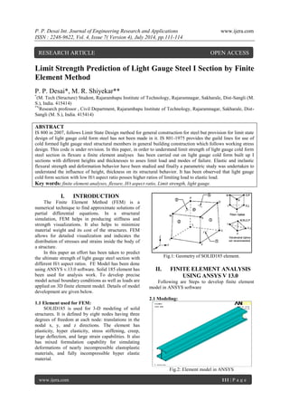
- 1. P. P. Desai Int. Journal of Engineering Research and Applications www.ijera.com ISSN : 2248-9622, Vol. 4, Issue 7( Version 4), July 2014, pp.111-114 www.ijera.com 111 | P a g e Limit Strength Prediction of Light Gauge Steel I Section by Finite Element Method P. P. Desai*, M. R. Shiyekar** *(M. Tech (Structure) Student, Rajarambapu Institute of Technology, Rajaramnagar, Sakharale, Dist-Sangli (M. S.), India. 415414) **(Research professor , Civil Department, Rajarambapu Institute of Technology, Rajaramnagar, Sakharale, Dist- Sangli (M. S.), India. 415414) ABSTRACT IS 800 in 2007, follows Limit State Design method for general construction for steel but provision for limit state design of light gauge cold form steel has not been made in it. IS 801-1975 provides the guild lines for use of cold formed light gauge steel structural members in general building construction which follows working stress design. This code is under revision. In this paper, in order to understand limit strength of light gauge cold form steel section in flexure a finite element analyses has been carried out on light gauge cold form built up I sections with different heights and thicknesses to asses limit load and modes of failure. Elastic and inelastic flexural strength and deformation behavior have been studied and finally a parametric study was undertaken to understand the influence of height, thickness on its structural behavior. It has been observed that light gauge cold form section with low H/t aspect ratio posses higher ratios of limiting load to elastic load. Key words: finite element analyses, flexure, H/t aspect ratio, Limit strength, light gauge. I. INTRODUCTION The Finite Element Method (FEM) is a numerical technique to find approximate solutions of partial differential equations. In a structural simulation, FEM helps in producing stiffness and strength visualizations. It also helps to minimize material weight and its cost of the structures. FEM allows for detailed visualization and indicates the distribution of stresses and strains inside the body of a structure. In this paper an effort has been taken to predict the ultimate strength of light gauge steel section with different H/t aspect ratios. FE Model has been done using ANSYS v.13.0 software. Solid 185 element has been used for analysis work. To develop precise model actual boundary conditions as well as loads are applied on 3D finite element model. Details of model development are given below. 1.1 Element used for FEM: SOLID185 is used for 3-D modeling of solid structures. It is defined by eight nodes having three degrees of freedom at each node: translations in the nodal x, y, and z directions. The element has plasticity, hyper elasticity, stress stiffening, creep, large deflection, and large strain capabilities. It also has mixed formulation capability for simulating deformations of nearly incompressible elastoplastic materials, and fully incompressible hyper elastic material. Fig.1: Geometry of SOLID185 element. II. FINITE ELEMENT ANALYSIS USING ANSYS V 13.0 Following are Steps to develop finite element model in ANSYS software 2.1 Modeling: Fig.2: Element model in ANSYS RESEARCH ARTICLE OPEN ACCESS
- 2. P. P. Desai Int. Journal of Engineering Research and Applications www.ijera.com ISSN : 2248-9622, Vol. 4, Issue 7( Version 4), July 2014, pp.111-114 www.ijera.com 112 | P a g e Mechanical APDL method is used to built FE model. Above figure shows FE model created in ANSYS. 2.2 Meshing: The important step of FE method is meshing, size of mesh depends upon parent material to be modeled also the degree of accuracy required. Results can be significantly changed if proper meshing size is not decided. For this FE model meshing size is kept 20. Following figure shows meshed model in ANSYS. Fig.3: Meshing of FE model 2.3 Analysis and result prediction: Fig.4: Deformed shape of FE model With the use of static nonlinear analysis strength have been predicted of light gauge steel sections. Figure above shows deformed shape of FE Model in ANSYS. 2.4 Details of Light gauge sections analyzed using ANSYS: Four different light gauge sections have been modeled and analyzed with the help of ANSYS. For better strength prediction H/t ratio is kept different for each of the section. a. 120C20 b. 120C25 c. 200C20 d. 200C25 Fig.5 Cross sectional properties of C sections ‘a’ and ‘b’ Fig. 6: Cross sectional properties of C sections ‘c’ and ‘d’ Table below gives detailed information about analyzed sections. Table 1: Cross sectional properties of C sections Section Weight (per meter) Thickness (mm) Length (mm) c/s Area (cm2) Ixx (cm4) Iyy (cm4) H/t ratio 120C20 4.08 2 17.43 5.20 120.25 25.97 55 120C25 5.10 2.5 18.65 6.50 148.55 32.34 43.60 200C20 6.1 2 20 7.80 491.7 73.37 92 200C25 7.65 2.5 21.2 9.75 610.6 91.76 73.2
- 3. P. P. Desai Int. Journal of Engineering Research and Applications www.ijera.com ISSN : 2248-9622, Vol. 4, Issue 7( Version 4), July 2014, pp.111-114 www.ijera.com 113 | P a g e III. RESULT AND DISCUSSION: 3.1: Finite element method result for light gauge steel a. Light gauge steel section 120C20 Fig .7: Load v/s Deflection curve for 120C20 by ANSYS Load v/s Deflection curve shown by Fig 5.15 follows good linear behavior till if reaches load of 46 KN then changing the nature of curve showing plastic deformation section fails at load of 64 KN. Table 2: Load and deflection results for Light gauge I section 120C20 by ANSYS Elastic load(KN) Deflection (mm) Limit load(KN) Deflection (mm) Ratio of Limit load to elastic load 46 0.65 64 3.29 1.39 b. Light gauge steel section 120C25 Fig.8: Load v/s Deflection curve for 120C25 by ANSYS Almost same nature of curve have been observed for this section also but this section shows higher ratio of Limit load to elastic load Table 3: Load and deflection results for Light gauge I section 120C25 by ANSYS Elastic load(KN) Deflection (mm) Limit load(KN) Deflection (mm) Ratio of Limit load to elastic load 60 0.9 88 3.38 1.46 c. Light gauge steel section 200C20: Fig.9: Load v/s Deflection curve for 200C20 by ANSYS Table 4: Load and deflection results for Light gauge I section 200C20 by ANSYS Elastic load(KN) Deflection (mm) Limit load(KN) Deflection (mm) Ratio of Limit load to elastic load 52 0.43 66 0.86 1.26 d. Light gauge steel section 200C25: Fig.10: Load v/s Deflection curve for 200C25 by ANSYS 0.00 10.00 20.00 30.00 40.00 50.00 60.00 70.00 0.00 0.50 1.00 1.50 2.00 2.50 3.00 3.50 LOAD (KN) DELECTION (mm) 0.00 20.00 40.00 60.00 80.00 100.00 0 0.5 1 1.5 2 2.5 3 3.5 4 LOAD (KN) DEFLECTION (mm) 0.00 10.00 20.00 30.00 40.00 50.00 60.00 70.00 0.00 0.50 1.00 LOAD (KN) DEFLECTION (mm) 0.00 20.00 40.00 60.00 80.00 100.00 0.00 0.50 1.00 LOAD (KN) DEFLECTION (mm)
- 4. P. P. Desai Int. Journal of Engineering Research and Applications www.ijera.com ISSN : 2248-9622, Vol. 4, Issue 7( Version 4), July 2014, pp.111-114 www.ijera.com 114 | P a g e Fig and Fig show very much linear variation in Load v/s Deflection curve which show sections with high H/t ratio are unable to reach its plastic state. This is because of local buckling failure of compression flanges of light gauge section. Table 5: Load and deflection results for Light gauge I section 200C25 by ANSYS Elastic load( KN) Deflection (mm) Limit load(KN) Deflection (mm) Ratio of Limit load to elastic load 68 0.47 88 0.89 1.29 IV. CONCLUSION Above study shows built up I section using Light gauge steel with lower H/t aspect ratio behaves significantly showing elastic and plastic deformation both. With increment in H/t aspect ratio this behavior changes and shows failure in elastic zone. Observed failure is due to local buckling of compression flange It has been observed that the ratio of limit strength of light gauge section in bending to it’s corresponding elastic strength is greater when H/t ratio is lower, where as with increase in H/t aspect ratio, this ratio of limit strength to elastic strength drops significantly. REFERENCES [1] Cilmar Basaglia and Dinar Camotim,” Buckling, Post buckling, Strength, and DSM Design of Cold-Formed Steel Continuous Lipped Channel Beams”, Journal of structural engineering, ASCE Vol. 139, May 2013.Page No. 657-668. [2] Luis Laim, Joao Paulo C. Rodrigues and Luis Simoes da Silva,” Experimental and numerical analysis on the structural behavior of cold-formed steel beams”, Journal of thin walled structures, Elsevier,2013,Vol. 72, Page No. 1-13 [3] M. Macdonald, M.A. Heiyantuduwa and J. Rhodes,” Recent developments in the design of cold-formed steel members and structures” Journal of thin walled structures, Elsevier,2008,Vol. 46, Page No. 1047-1053. [4] Mohammad Reza Haidarali and David A. Nethercot,” Finite element modeling of cold- formed steel beams under local buckling or combined local/distortional buckling” Journal of thin walled structures, Elsevier,2011,Vol. 49, Page No. 1554-1562 [5] Mohammad Reza Haidarali and David A. Nethercot,” Local and distortional buckling of cold-formed steel beams with both edge and intermediate stiffeners in their compression flanges” Journal of thin walled structures, Elsevier, 2012, Vol. 54, Page No. 106-112.