Cw33592595
•
0 likes•152 views

This document compares various dissolved gas analysis (DGA) methods for diagnosing transformer faults, including Rogers ratio, IEC ratio, Doernenburg, Duval triangle, key gas, and artificial neural network methods. It evaluates these methods based on their ability to successfully predict different fault types (F1-F5) using DGA data from previous studies. The results show that the Duval gas and key gas methods achieved 100% accuracy for some fault types, while the IEC method had the highest accuracy of 82% for fault type F3. Overall, the Duval gas method and key gas method were the most consistent according to the analysis.
![S. Saranya, Uma Mageswari, Natalya Roy, R. Sudha / International Journal of Engineering
Research and Applications (IJERA) ISSN: 2248-9622 www.ijera.com
Vol. 3, Issue 3, May-Jun 2013, pp.592-595
593 | P a g e
is observed by discharged in gas filled cavities
from incomplete impregnation. Partial discharge of
high energy density leads to perforation of solid
insulation. Thermal faults are observed by
overheating of insulation conductors.
3. Doernenburg Ratio Method:
In this method the gas concentration from
ratio of CH4/H2, C2H2/CH4, C2H4/C2H6 and
C2H2/C2H4 are utilised. The value of gases must
exceed the concentration L1 when there is fault at
the unit. Table (5) shows the key gases and their
concentration L1.
Table (5):
To diagnose the fault the step by step procedure in
this method is:
Gas concentrations are obtained by
extracting the gases and separating them
by chromatograph
If at least one of the gas concentrations (in
ppm) for H2, CH4, C2H2, and C2H4
exceeds twice the values for limit L1 (see
table 7) and one of the other three gases
exceeds the values for limit L1, the unit is
considered faulty; proceed to Step 3.
Determining validity of ratio procedure: If
at least one of the gases in each ratio
CH
4
/H
2
, C
2
H
2
/CH
4
, C
2
H
2
/CH
4
and
C
2
H
6
/C
2
H
2
exceeds limit L1, the ratio
procedure is valid. Otherwise, the ratios
are not significant, and the unit should be
resample and investigated by alternative
procedures.
Assuming that the ratio analysis is valid,
each successive ratio is compared to the
values obtained from table 8 in the order
of ratio CH
4
/H
2
, C
2
H
2
/CH
4
, C
2
H
2
/CH
4
and
C
2
H
6
/C
2
H
2
If all succeeding ratios for a specific fault type fall
within the values (column) given in table(6), the
suggested diagnosis is valid.
Table(6):
Suggested
Fault
diagnosis
1.thermal
decomposi
tion
2.corona(
low
Intensity
PD)
3.arcing
(high
intensity
PD)
CH4/H2 >1.0
>0.1
<0.75
<1.0
<0.3
<0.1
C2H2/C2H4 <0.1
<0.01
Not
significia
nt
<0.3
<0.1
C2H2/CH4 <0.1
>0.01
<1.0
<0.1
>0.75
>1.0
>0.3
>0.1
4. Duval Triangle method:
This method was developed in 1960 by
M.Duval. To determine whether the problem exists
at least the one of the hydro carbon gases or
hydrogen must be at L1 level or above , and the gas
generation rate must be at least G2[]. The L1 level
and gas generation rates are shown in table (7).
Table(7):
Gas L1 limits G1 limits
(ppm per
month)
G2 limits
(ppm per
month)
H2 100 10 50
CH4 75 8 38
C2H2 3 3 3
C2H4 75 8 38
C2H6 75 8 38
CO 700 70 350
CO2 7000 700 3500
Once a problem has been detected, calculate the
total accumulated Amount of the three Duval
triangle gases (CH4, C2H2, C2H4) and divide each
gas by the total.](data:image/gif;base64,R0lGODlhAQABAIAAAAAAAP///yH5BAEAAAAALAAAAAABAAEAAAIBRAA7)
Recommended
Recommended
More Related Content
Viewers also liked
Similar to Cw33592595
Similar to Cw33592595 (20)
Recently uploaded
Recently uploaded (20)
Cw33592595
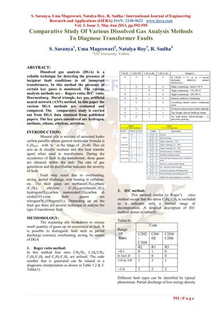
- 1. S. Saranya, Uma Mageswari, Natalya Roy, R. Sudha / International Journal of Engineering Research and Applications (IJERA) ISSN: 2248-9622 www.ijera.com Vol. 3, Issue 3, May-Jun 2013, pp.592-595 592 | P a g e Comparative Study Of Various Dissolved Gas Analysis Methods To Diagnose Transformer Faults S. Saranya1 , Uma Mageswari2 , Natalya Roy3 , R. Sudha4 4 VIT University, Vellore ABSTRACT: Dissolved gas analysis (DGA) is a reliable technique for detecting the presence of incipient fault conditions in oil immersed transformers. In this method the presence of certain key gases is monitored. The various analysis methods are : Rogers ratio, IEC ratio, Doernenburg, Duval triangle, key gas, artificial neural network (ANN) method. In this paper the various DGA methods are evaluated and compared. The comparative study is carried out from DGA data obtained from published papers. The key gases considered are hydrogen, methane, ethane, ethylene, acetylene. INTRODUCTION: Mineral oils is mixture of saturated hydro carbon paraffin whose general molecular formula is CnH2n+2 with ‘n ‘ in the range of 20-40. This oil acts as di electric medium and this heat transfer agent when used in transformers. During the occurrence of fault in the transformer, these gases are released within the unit. The rate of gas generation and its distribution indicates the severity of fault. Fault may occur due to overheating, arcing, partial discharge, over heating in cellulose, etc. The fault gases are methane(CH4),ethane (C2H6), ethylene (C2H4),acetylene(C2H2), hydrogen(H2),carbon monoxide(CO),carbon di oxide(CO2).non fault gasses are nitrogen(N2),Oxygen(O2). Depending up on the fault gas there are several technique to analyse the type if transformer fault. METHODOLOGY: The insulating oils breakdown to release small quantity of gases up on occurrence of fault. It is possible to distinguish fault such as partial discharge (corona), overheating, arcing, by means of DGA 1. Roger ratio method: In this method four ratio CH4/H2, C2H6/CH4, C2H4/C2H6 and C2H2/C2H4 are utilised. The code number that is generated can be related to a diagnostic interpretation as shown in Table 1,2 & 3. Table(1): 2. IEC method: This method similar to Roger’s ratio method except that the ratios C2H6/CH4 is excluded as it indicates only a limited range of decomposition. A detailed description of IEC method shown in table(4). Table(4): Range Of Ratio Code C2H2 / C2H4 CH4/ H2 C2H4/ C2H6 R2 R1 R5 <0.1 0 1 0 0.1to1.0 1 0 0 1.0 to 3.0 1 2 1 >3.0 2 2 2 Different fault types can be identified by typical phenomena. Partial discharge of low energy density
- 2. S. Saranya, Uma Mageswari, Natalya Roy, R. Sudha / International Journal of Engineering Research and Applications (IJERA) ISSN: 2248-9622 www.ijera.com Vol. 3, Issue 3, May-Jun 2013, pp.592-595 593 | P a g e is observed by discharged in gas filled cavities from incomplete impregnation. Partial discharge of high energy density leads to perforation of solid insulation. Thermal faults are observed by overheating of insulation conductors. 3. Doernenburg Ratio Method: In this method the gas concentration from ratio of CH4/H2, C2H2/CH4, C2H4/C2H6 and C2H2/C2H4 are utilised. The value of gases must exceed the concentration L1 when there is fault at the unit. Table (5) shows the key gases and their concentration L1. Table (5): To diagnose the fault the step by step procedure in this method is: Gas concentrations are obtained by extracting the gases and separating them by chromatograph If at least one of the gas concentrations (in ppm) for H2, CH4, C2H2, and C2H4 exceeds twice the values for limit L1 (see table 7) and one of the other three gases exceeds the values for limit L1, the unit is considered faulty; proceed to Step 3. Determining validity of ratio procedure: If at least one of the gases in each ratio CH 4 /H 2 , C 2 H 2 /CH 4 , C 2 H 2 /CH 4 and C 2 H 6 /C 2 H 2 exceeds limit L1, the ratio procedure is valid. Otherwise, the ratios are not significant, and the unit should be resample and investigated by alternative procedures. Assuming that the ratio analysis is valid, each successive ratio is compared to the values obtained from table 8 in the order of ratio CH 4 /H 2 , C 2 H 2 /CH 4 , C 2 H 2 /CH 4 and C 2 H 6 /C 2 H 2 If all succeeding ratios for a specific fault type fall within the values (column) given in table(6), the suggested diagnosis is valid. Table(6): Suggested Fault diagnosis 1.thermal decomposi tion 2.corona( low Intensity PD) 3.arcing (high intensity PD) CH4/H2 >1.0 >0.1 <0.75 <1.0 <0.3 <0.1 C2H2/C2H4 <0.1 <0.01 Not significia nt <0.3 <0.1 C2H2/CH4 <0.1 >0.01 <1.0 <0.1 >0.75 >1.0 >0.3 >0.1 4. Duval Triangle method: This method was developed in 1960 by M.Duval. To determine whether the problem exists at least the one of the hydro carbon gases or hydrogen must be at L1 level or above , and the gas generation rate must be at least G2[]. The L1 level and gas generation rates are shown in table (7). Table(7): Gas L1 limits G1 limits (ppm per month) G2 limits (ppm per month) H2 100 10 50 CH4 75 8 38 C2H2 3 3 3 C2H4 75 8 38 C2H6 75 8 38 CO 700 70 350 CO2 7000 700 3500 Once a problem has been detected, calculate the total accumulated Amount of the three Duval triangle gases (CH4, C2H2, C2H4) and divide each gas by the total.
- 3. S. Saranya, Uma Mageswari, Natalya Roy, R. Sudha / International Journal of Engineering Research and Applications (IJERA) ISSN: 2248-9622 www.ijera.com Vol. 3, Issue 3, May-Jun 2013, pp.592-595 594 | P a g e This will give the percentage of each gas of the total. Plot the obtained percentage of the total on the triangle to obtain the diagnosis. 5. Key Gas method: The principle of the key gas method is based on the quantity of individual fault gases released from the insulating oil during the occurrence of a fault. In this method, individual gas is considered rather than the gas ratio for fault detection is calculated. Table(8): Over Heated Oil Characteristic Table(9): Overheated Cellulose Characteristic Table (10): Corona in Oil Characteristic Table (11): Arcing in oil Characteristic 6. Artificial Intelligence: The relationship between released gas and incipient fault condition is interpreted by ANN and is used to develop the gas- in- oil data. An ANN design includes selection of input, output, network topology and weighted connection of nodes. The network topology is chosen experimentally through a repeated process of optimization of the number of hidden layers. Figure () illustrates over all ANN design process with step by step adjustment to achieve desired structure. The back propagation learning algorithm used involves repeatedly passing the training sets through the neural network until it weights minimise the output error over the entire set. Once a process has done, the weights will be retained and ready for future use. New samples can be fed to this trained ANN to obtain the output readily. Results and Conclusions: The percentage of successful prediction and consistency are calculated using the following formulas:
- 4. S. Saranya, Uma Mageswari, Natalya Roy, R. Sudha / International Journal of Engineering Research and Applications (IJERA) ISSN: 2248-9622 www.ijera.com Vol. 3, Issue 3, May-Jun 2013, pp.592-595 595 | P a g e TABLE(13): From the results summarised in the table the following observations are made For f1 faults key gas and duval methods ds gave 100% successful predictions. For F2 faults key gas method gave 100% successful prediction. For f3 faults the IEC method gave the highest percentage of successful prediction at 82% F4 faults had the lowest percentage of successful prediction among all fault types. F5 faults Duval Gas method gave 100% successful prediction. It can be observed that the most consistent method is the duval gas method followed by key gas method. References: 1. Artificial neural networks applied to DGA for fault diagnosis in oil-filled power transformers: Mohammad Golkhah, Sahar Saffar Shamshirgar and Mohaammad Ali Vahidi. 2. An Artificial Neural Network approach to Transformer Fault Diagnosis. Y. Zhang, X. Ding, Y. Liu, P. J. GriffinThe Bradley Department of Electrical EngineeringVirginia Tech, Blacksburg, VA 24061-0111,USA 3. DiGiorgio, J.B. (2005) Dissolved Gas Analysis of Mineral Oil Insulating Fluids. DGA Expert System: A Leader in Quality, Value and Experience 1, 1-17 4. Chu, D. and A. Lux, On-line monitoring of power transformers and components: a review of key parameters. Electrical Insulation Conference and Electrical Manufacturing & Coil Winding Conference, 1999. Proceedings, 1999: p. 669-675. 5. Siva Sarma, D.V.S.S. and G.N.S. Kalyani, ANN Approach for Condition Monitoring of Power Transformers using DGA. 2004 IEEE Region 10 Conference, TENCON 2004., 2004. C: p. 444-447. 6. Yang, F. and Z. Liang, Comprehensive method detecting the status of the transformer based on the artificial intelligence. 2004 International Conference on Power System Technology, 2004. PowerCon 2004. , 2004. 2: p. 1638- 1643. 7. Hongzhong, M., et al., Diagnosis of power transformer faults on fuzzy three-ratio method. The 7th International Power Engineering Conference, 2005. IPEC 2005., 2005. 8. Wang, M., A.J. Vandermaar, and K.D. Srivastava, Review of Condition Assessment of Power Transformers In Service, in IEEE Electrical Insulation Magazine. 2002. p. 12-25. 9. C57.104.1991, I., IEEE Guide for Interpretation of Gases Generated in Oil- Immersed Transformer, I. The Institute of Electrical and Electronic Engineers, Editor. 1992, The Institute of Electrical and Electronic Engineers, Inc p. 27. 10. FIST3-31, Facilities Instructions, Standards and Techniques Volume 3-31 Transformer Diagnostics. 2003, Bureau of Reclamation Hydroelectric Research and Technical Services Group Denver. p. 5-13. 11. Q.Su, et al., A Fuzzy Dissolved Gas Analysis Method for The Diagnosis of Multiple Incipient Faults in a Transformer. IEEE Transaction On Power System, 2000. 15(2): p. 593-59