Bw044452460
•
0 likes•264 views

Electronics & Communication Engineering, Computational mathematics, Image processing, Civil Engineering, Structural Engineering, Environmental Engineering, VLSI Testing & Low Power VLSI Design etc.
![D.Asirinaidu et al Int. Journal of Engineering Research and Applications www.ijera.com
ISSN : 2248-9622, Vol. 4, Issue 4( Version 1), April 2014, pp.452-460
www.ijera.com 453 | P a g e
Metal structures are subject to corrosion, and
some kinds of corrosion are accelerated in the
presence of stress. Aircraft structures are designed
with particular attention to weight, for obvious
reasons. If we could see beneath the interior fittings
of passenger aircraft, we would see numerous
lightening holes in the frames as well as regions
where the skins have been thinned by chemical
milling.
1.2 LAYOUT OF THE AIRCRAFT WING
The first aircraft had two wings made of light weight
wood frames with cloth skins, held apart by wires and
struts.
In the 1920s, metal began to be used for
aircraft structure. A metal wing is a box structure with
the skins comprising the top and bottom, with front
and back formed by I-beams called spars, interior
fore-aft stiffeners called ribs, and in-out stiffeners
called stringers. In level flight, the lower skin is in
tension while the upper skin is in compression.
1.3 STRINGER PANEL
The weld joint in the stringer should be in the web
close to the skin panel and the thickness of all weld
samples are 7mm after post-weld machining. The
final design configuration was shown in Fig. ,it is like
―T‖.
II. FRICTION STIR WELDING:
Friction stir welding (FSW) is a relatively
new (1991) solid-state welding technique. In FSW, a
rotating tool traverses along the joint seam of the
material to be joined and accomplishes welding via
mechanical stirring. It was First patented in Great
Britain by Wayne Thomas et al from the Welding
Institute in 1991 [Thomas et al., 1991a].The United
States Patent is dated 1995 [Thomas et al., 1995].
The FSW tool rotates about its axis and the probe (or
pin) plunges into the material. The shoulder of the
tool applies force to the top of the material. Heat is
generated through the downward force on the
shoulder which softens the material along the joint
line. The tool then traverses along the weld line, and
the rotating tool probe drags the plasticized material
to the back of the probe. This causes the solid-state
joining of the material [Khaled, 2005]
F
Fig. 2.1: Schematic drawing of the Friction
Stir welding (Thomas et al. 1991)
The emergence of the FSW alters the traditional
approach for producing lightweight assemblies.](data:image/gif;base64,R0lGODlhAQABAIAAAAAAAP///yH5BAEAAAAALAAAAAABAAEAAAIBRAA7)
Recommended
Recommended
More Related Content
What's hot
What's hot (18)
Viewers also liked
Viewers also liked (20)
Similar to Bw044452460
Similar to Bw044452460 (20)
Recently uploaded
Recently uploaded (20)
Bw044452460
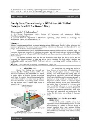
- 1. D.Asirinaidu et al Int. Journal of Engineering Research and Applications www.ijera.com ISSN : 2248-9622, Vol. 4, Issue 4( Version 1), April 2014, pp.452-460 www.ijera.com 452 | P a g e Steady State Thermal Analysis Of Friction Stir Welded Stringer Panel Of An Aircraft Wing D.Asirinaidu1 , D.Lokanadham2 1 .M.E(Thermal Engg.)student, Aditya Institute of Technology and Management, Tekkali. Email:dasirinaidu@gmail.com 2. Associate Professor, Department of Mechanical Engineering, Aditya Institute of Technology and Management, Tekkali, Srikakulam Dist.-532201. Abstract— Welding is a wide range multistate permanent fastening method of fabrication. Globally welding technology has numerous applications. The present project deals with the calculation of the steady state thermal analysis and fatigue life of the friction stir welded stringer panel. The stringer panel is a device used for supporting the upper and the lower skin of the aircraft wing. The equivalent stresses and life cycles are calculated theoretically referring to many journals, the theoretical inputs are given to the analysis software ANSYS Workbench i.e. heat flux, temperature, and speed of rotation of the friction stir tool. The resultant equivalent stress and the total deformation apart from that the life cycles are also generated. The theoretical values of stress and fatigue life are computed. The best welding conditions are predicted by suitable analysis in ANSYS Work bench software by providing suitable working conditions as inputs. Keyword – ANSYS, Friction stir welding, Thermal analysis, Fatigue life. I. INTRODUCTION Friction Stir Welding was invented and patented by The Welding Institute in1991. The process uses a spinning, non-consumable tool, similar to a taper reamer, to generate frictional heat in the work piece. By pressing this tool into contact with a seam to be welded, the base metal heats up and once it reaches about 80% of its melting point it becomes soft and deforms easily. A typical FSW system is shown in Fig 1.1. Fig 1.1 The principle of Friction Stir Welding By keeping the tool rotating and moving it along the seam to be joined, the softened material is literally stirred together forming a weld without melting. These welds require low energy input and are without the use of filler materials and distortion. Initially developed for non-ferrous materials such as aluminum, by using suitable tool materials the use of the process has been extended to harder and higher melting point materials such as steels titanium alloys and copper. Since its conception in 1991 there have been considerable advances in process technology and there are now over 135 licensees of the process and over 1500 subsidiary patents have been filed. This paper will concentrate on improvements for tooling for the friction stir welding of aluminum alloys. 1.1 INTRODUCTION TO THE AIRCRAFT STRUCTURE: Aircraft Structural weight has always been important in aircraft manufacturing industry. Aircraft structural design is a subset of structural design in general, including ships, land vehicles, bridges, towers, and buildings. All structures must be designed with care because human life often depends on their performance. RESEARCH ARTICLE OPEN ACCESS
- 2. D.Asirinaidu et al Int. Journal of Engineering Research and Applications www.ijera.com ISSN : 2248-9622, Vol. 4, Issue 4( Version 1), April 2014, pp.452-460 www.ijera.com 453 | P a g e Metal structures are subject to corrosion, and some kinds of corrosion are accelerated in the presence of stress. Aircraft structures are designed with particular attention to weight, for obvious reasons. If we could see beneath the interior fittings of passenger aircraft, we would see numerous lightening holes in the frames as well as regions where the skins have been thinned by chemical milling. 1.2 LAYOUT OF THE AIRCRAFT WING The first aircraft had two wings made of light weight wood frames with cloth skins, held apart by wires and struts. In the 1920s, metal began to be used for aircraft structure. A metal wing is a box structure with the skins comprising the top and bottom, with front and back formed by I-beams called spars, interior fore-aft stiffeners called ribs, and in-out stiffeners called stringers. In level flight, the lower skin is in tension while the upper skin is in compression. 1.3 STRINGER PANEL The weld joint in the stringer should be in the web close to the skin panel and the thickness of all weld samples are 7mm after post-weld machining. The final design configuration was shown in Fig. ,it is like ―T‖. II. FRICTION STIR WELDING: Friction stir welding (FSW) is a relatively new (1991) solid-state welding technique. In FSW, a rotating tool traverses along the joint seam of the material to be joined and accomplishes welding via mechanical stirring. It was First patented in Great Britain by Wayne Thomas et al from the Welding Institute in 1991 [Thomas et al., 1991a].The United States Patent is dated 1995 [Thomas et al., 1995]. The FSW tool rotates about its axis and the probe (or pin) plunges into the material. The shoulder of the tool applies force to the top of the material. Heat is generated through the downward force on the shoulder which softens the material along the joint line. The tool then traverses along the weld line, and the rotating tool probe drags the plasticized material to the back of the probe. This causes the solid-state joining of the material [Khaled, 2005] F Fig. 2.1: Schematic drawing of the Friction Stir welding (Thomas et al. 1991) The emergence of the FSW alters the traditional approach for producing lightweight assemblies.
- 3. D.Asirinaidu et al Int. Journal of Engineering Research and Applications www.ijera.com ISSN : 2248-9622, Vol. 4, Issue 4( Version 1), April 2014, pp.452-460 www.ijera.com 454 | P a g e Boeing has reduced cost and production time with the FSW on pressure vessels (Johnsen 1999). Likewise, Eclipse aviation began using FSW to join skin structures and Hitachi has applied this technology to the welding of aluminum skin structures in their trains in anticipation of large cost and time savings (Ohba et al. 2001). Complex material movement and plastic deformation contribute significantly to the physical mechanism of FSW. Tool geometry, welding parameters, and joint design significantly influence the material flow. Figure 2.2 shows the FSW tool which consists of a shoulder and a pin. The shape and relative size of the pin and the shoulder are important for maximizing the heat generation, which aids the material flow and reduces welding force. Fig. 2.2: Schematic drawing of the FSW tool (Mishra and Ma 2005) (a) Three flutes (b) left hand helix on Outer diameter land Fig. 2.3: (a) Work tool (b) MX triflute tool (Thomas et al. 2003) TWI (Thomas et al. 2003) has developed several types of tools like the worl and MX triflute tools as shown in Figure 2.3. It has been suggested that these design features reduce required welding forces, enable easier flow of plasticized material, facilitate a downward auguring effect, and increase the interface surface area between the pin and material. Zhao et al. (Zhao et al. 2005) investigated the influence of the pin geometry on bonding and mechanical properties in friction stir welded Al alloys. He claimed that pin design affects the flow of the plastic material strongly. The best quality weld was acquired using a tapered screw threaded pin. Figure 2.4 shows the four visually distinct micro structural zones in which welds in aluminum are typically divided into: (a) Unaffected parent material, (b) Heat affected zone, (c) Thermo-mechanically affected zone, and (d) Weld nugget. In the heat affected zone, properties and microstructure are affected by the heat from the weld, although there is no mechanical deformation. This zone retains the same grain structure as the parent materials. The thermo-mechanically affected zone shows characteristics that suggest that it underwent plastic deformation but recrystallization did not occur in this zone due to insufficient deformation strain. In weld nugget zone, intense plastic deformation and frictional heating during FSW result in recrystallized fine-grained microstructure (Threadgill 1999). Fig 2.4 : (a) Schematic diagram of micro structural zones in friction stir welds in aluminum (b) micrograph showing various micro-structural zones (Threadgill 1999) III. INTRODUCTION TO EXPERIMENT The objective of this paper is to investigate optimum process parameters in friction stir welding to determine the induced stresses and the fatigue life in the Stringer Panel. More specifically , the choice of tool rotational speed have been sought with a steady, 2 dimensional sequentially coupled thermo mechanical model implemented in FE-Code, ANSYS. The thermal model is based on a heat source description which in essence is governed by the rotational speed and the temperature dependent yield stress of the work piece material. This model in turn delivers the temperature field, in order to compute thermal strain field which is the main driver for mechanical model predicting both transient and finally residual stresses in the work piece.
- 4. D.Asirinaidu et al Int. Journal of Engineering Research and Applications www.ijera.com ISSN : 2248-9622, Vol. 4, Issue 4( Version 1), April 2014, pp.452-460 www.ijera.com 455 | P a g e Most pure thermal models apply a surface flux as representing the entire heat generation, thereby avoiding the source term in the heat conduction equation, which is governed by the plastic dissipation and therefore in essence calls for knowledge about the material flow and hence the formation of the shear layer. In this model the heat generation is expressed as a surface heat flux from the tool shoulder (without the tool probe) into work piece, however it is the function of the tool radius and the temperature dependent yield stress as follows. (r, T) = .... [1] For 0 ≤ r ≤ R Where n is the tool revolution per minute, r is the pin radius originating in the tool center, R is the tool shoulder radius and the temperature dependent yield stress, is defined as = … [2] where, is the yield stress at room temperature. is 20°C and is solidus temperature which is 1000°C. Once the temperature reaches the solidus temperature, i.e. T is equal to as in Eq.[2], the self stabilizing effect causes the heat generation decreases automatically due to thermal softening. The model is often denoted ―Thermal-Pseudo- Mechanical‖ since the heat generation is expressed via the temperature dependent yield stress, thus taking some mechanical effects into. 3.1 CHOICE OF MATERIAL: For the present problem of analyzing the Stringer Panel we take the material of ALUMINIUM 7075.the following are some of the properties tabulated. Structural Young's Modulus 16000 MPa Poisson's Ratio 0.33 Density 2.77e-006 kg/mm³ Thermal Expansion 2.3e-005 1/°C Tensile Yield Strength 280. MPa Compressive Yield Strength 280. MPa Tensile Ultimate Strength 310. MPa Thermal Specific Heat 875. J/kg·°C Resistivity 5.7e-005 Ohm-mm Melting point 482.22 °C Lower Forging Temperature 260 °C Upper Forging Temperature 371.11 °C 3.2 STRESS CALCULATIONS AT FOLLOWING TEMPERATURES Theoretical stress values can be calculated by using following formula = At 150°C the theoretical yield stress is: = 420 x { 1- } = 308.49 MPa. At 200°C the theoretical yield stress is: = 420 x { 1- } = 262 MPa. At 260°C the theoretical yield stress is: = 420 x { 1- } = 202.7 MPa. At 371°C the theoretical yield stress is: = 420 x { 1- } = 101.34 MPa. 3.3 CALCULATIONS FOR HEAT FLUX Heat flux can be calculated by using the formula: Heat flux (ø): (Qsur/Area) = ωr = x At radius 4 mm and at σ(T) = 308.49MPa, the heat flux observed is: Ø = x x = 74.60 x 10⁵ W/m2 . Similarly at radius 4 mm and at σ(T) = 262MPa, the heat flux observed is:
- 5. D.Asirinaidu et al Int. Journal of Engineering Research and Applications www.ijera.com ISSN : 2248-9622, Vol. 4, Issue 4( Version 1), April 2014, pp.452-460 www.ijera.com 456 | P a g e Similarly at radius 4 mm and at σ (T) = 202.7 MPa, the heat flux observed is: Ø = x x = 49.02 x 10⁵ W/m2 . Similarly at radius 4 mm and at σ (T) = 371 MPa, the heat flux observed is: Ø = x x = 89 x 105 W/m2 . Therefore heat flux and stress calculations are calculated. 3.4 INPUTS GIVEN IN CATIA Specification of Stringer Panel Dimension (mm) Thickness of the structure along web and top flange region 7 Thickness of the structure along bottom flange 6 Width of the top flange 50 Height of the web 59 Total height of the structure 77 Total bottom length of the two Flanges 350 In between space provided for the weld between top and the bottom joint 3 Distance in between the two flange heads 120 Total length of the Stringer Panel 1240 3.5 STEPS TO SOLVE PROBLEM IN ANSYS Work bench The following are the steps required to solve the problem in ANSYS Work bench: STEP 1: Launch ANSYS Workbench STEP 2: Select GEOMETRY> FILE > IMPORT EXTERNAL GEOMETRY After importing the stp file (MODEL) return to the project. STEP 3: Select NEW SIMULATION > MESH >GENERATE MESH STEP 4: Select NEW ANALYSIS > STEADY STATE THERMAL ANALYSIS After selecting steady state thermal analysis the ambient and melting temperatures are given as inputs by selecting the corresponding surfaces. In addition to that heat flux or the heat flow is given followed by selecting the required lines at the interface in the model. STEADY STATE THERMAL ANALYSIS > ANALYSIS> INSERT> TEMPERATURE (AMBIENT) STEADY STATE THERMAL ANALYSIS > ANALYSIS> INSERT> TEMPERATURE (MELTING) STEADY STATE THERMAL ANALYSIS > ANALYSIS> INSERT> HEAT FLOW/HEAT FLUX. STEP 5: Select SOLUTION>TOTAL HEAT FLUX >DIRECTIONAL HEAT FLUX >TOTAL DEFORMATION >EQUIVALENT STRESS >NORMAL STRESS >SHEAR STRESS >DIRECTIONAL DEFORMATION STEP 6: Select ANALYSIS > FATIGUE>LIFE >DAMAGE >SAFETY FACTOR >EQUIVALENT ALTERNATING STRESS STEP 7: Right click on the SOLUTION > GENERATE > STEADYSTATE THERMAL STEP 8: SAVE the FILE in the Word Document. 3.6 INPUTS IN TO ANSYS WORK BENCH Speed rpm 100 200 400 Angular Vel(w), rad/s 10.472 20.944 41.888 σ yield(260°C) M Pa 202.7 202.7 202.7 Heat flux (W/m2 ) 49.02e5 98.4e5 196.08e5 σ yield(371°C) M Pa 101.25 101.25 101.25 Heat flux (W/m2 ) 24.49e5 48.97e5 97.95e5
- 6. D.Asirinaidu et al Int. Journal of Engineering Research and Applications www.ijera.com ISSN : 2248-9622, Vol. 4, Issue 4( Version 1), April 2014, pp.452-460 www.ijera.com 457 | P a g e Wing section of T-39 trainer undergoing fatigue testing 4. RESULTANT PLOTTING AFTER ANALYSIS 4.1 Geometry of the section: 1240 X 350 X 80 mm 4.2 MESH OF THE STRINGER PANEL STRUCTURE 4.3 Steady-State Thermal condition of 100 rpm and 260 o C 4.4 Temperature distribution along the STRINGER PANEL @ 100rpm and 260°C
- 7. D.Asirinaidu et al Int. Journal of Engineering Research and Applications www.ijera.com ISSN : 2248-9622, Vol. 4, Issue 4( Version 1), April 2014, pp.452-460 www.ijera.com 458 | P a g e 4.5 Total Heat Flux distribution at 100 rpm and 260 o C 4.6 Directional Heat Flux at 100 rpm and 260 o C 4.7 Normal Stress distribution over the stringer panel 100 rpm and 260 o C 4.8 RESULTS Stress (MPa) Life(cycles) @100 rpm 150 o C 300 2100 200 o C 254.7 32087 260 o C 194.65 56148 @200 rpm 150 o C 305 1600 200 o C 261 26942 260 o C 203 39556 @400 rpm 150 o C 318 900 200 o C 264 2404 260 o C 218 17326 5 GRAPHS 5.1 ANALYTICAL TEMPERATURE Vs LIFE GRAPH AT 400 rpm
- 8. D.Asirinaidu et al Int. Journal of Engineering Research and Applications www.ijera.com ISSN : 2248-9622, Vol. 4, Issue 4( Version 1), April 2014, pp.452-460 www.ijera.com 459 | P a g e 5.2 ANALYTICAL TEMPERATURE Vs LIFE GRAPH AT 100 rpm 5.3 ANALYTICAL TEMPERATURE Vs STRESS AT 150° C 5.4 ANALYTICAL SPEED Vs LIFE AT 100 RPM 5.5 ANALYTICAL TEMPERATURE Vs STRESS AT 260° C CONCLUSIONS The Stress and Life Cycles of Stringer Panel in the FRICTION STIR WELDING was analyzed and studied. From the results the following points are concluded: For a given speed at different temperatures the Life Cycles are Maximum at Higher Temperatures of the Stringer Panel i.e. 260o C with 56148 Life Cycles.(Graph 5.2) Stress component of the Stringer Panel in the Friction Stir Welding was minimum when the Speed of the Tool is minimum i.e. 100 rpm. (Graph 5.5) For different speeds of the Tool in the Friction Stir Welding at Lower Speeds the Life Cycles are Maximum.(Graph 5.4) REFERENCES [1] TWI (1991). Friction Stir welding atTWI [2] Mishra, R.S., Ma, Z.Y., Friction stir welding and processing, Materials Science and Engineering R, Vol. 50, 2005, pp. 1-78. [3] Static and Fatigue Testing of Full-Scale Aircraft Structures-Jody Cronenberger, Research Engineer Kenneth E. Griffin, Ph.D., Manager, Department of Structural Engineering Southwest Research Institute. [4] Structural RiskAssessment of RAAF B707 Lower Wing Stringers, Published by Air Vehicles Division DSTO Defence Science and Technology Organization 506 Lorimer St Fishermans Bend, Victoria 3207Australia.
- 9. D.Asirinaidu et al Int. Journal of Engineering Research and Applications www.ijera.com ISSN : 2248-9622, Vol. 4, Issue 4( Version 1), April 2014, pp.452-460 www.ijera.com 460 | P a g e [5] An Integrated Approach to the Determination and Consequences of Residual Stress on the Fatigue Performance of Welded Aircraft Structures, L. Edwards,1 M. E. Fitzpatrick,2 P. E. Irving,3 I. Sinclair,4 X. Zhang,5 and D. Yapp. Journal of ASTM International, February 2006, Vol. 3, No. 2. Paper ID JAI12547. [6] Building The World's Largest Passenger Aircraft Wings-Wikipedia [7] Case Study of Aircraft Wing Manufacture- Macintosh HD:Final book 16-19:Chapter 19 767 Case Study:Chapter_19.36i_767case.doc [8] Finite Element Based Fatigue Calculations Authors: Dr NWM Bishop† & Dr F Sherratt‡ NAFEMS-THE INTERNATIONAL ASSOCIATION FOR ENGINEERS ANALYSIS COMMUNITY [9] Fatigue,David Roylance Department of Materials Science and Engineering Massachusetts Institute ofTechnology. [10] ANSYS 10.0 Workbench Tutorial ANSYS, Inc. 275 Technology Drive Canonsburg, PA15317. [11] Wikipedia – Stringer Panel [12] RAJENDAR SINGH ‗Introduction to Basic Manufacturing Processes and Workshop Technology‘,Published by New Age International (P) Ltd., Publishers(2006). [13] CHUCK FENNELL Program Manager, Dalton Foundries RAJIV SHIVPURI ―Processes Manufacturing‖ Professor of Industrial, Welding, and Systems Engineering, Ohio State University OMER W. BLODGETT Senior Design Consultant, Lincoln Electric Co. DUANE K. MILLER Manager, Engineering Services, Lincoln Electric Co.(2003) [14] Thomas, W. M., Nicholas, E. D., Needham, J. C., Murch, M. G., Temple-Smith, P., and Dawes, C. J. Friction stir butt welding, International Patent Application PCT/GB92/02203, 1991. [15] Lee, W. B., Lee, C. Y., Chang, W. S., Yeon, Y. M., and Jung, S. B. Microstructural investigation of friction stir welded pure titanium. Mater. Lett., 2005, 59, 3315–3318. [16] Thomas, W. M. and Nicholas, E. D. Friction stir welding for the transportation industries. Mater. Des., 1997, 18, 269–273. [17] Zhang, H. W., Zhang, Z., and Chen, J. T. The finite element simulation of the friction stir welding process. Mater. Sci. Engng A, 2005, 403, 340–348. [18] Liu, H. J., Chen, Y. C., and Feng, J. C. Effect of zigzag line on the mechanical properties of Friction Stir Welded Joints of an Al–Cu Alloy. Scripta Mater., 2006,55, 231–234. [19] Zhang, H. W., Zhang, Z., and Chen, J. T. 3D Modeling of material flow in friction stir welding under different process parameters. J. Mater. Process. Technol., 2007,183, 62–70. [20] Zhang, Z., Chen, J. T., and Zhang, H. W. The 3D simulation of friction stir welding process. In Interna- tional Conference on Mechanical engineering and mechanics (Eds R. C. Batra, L. F. Qian, Y. L. Zhang, X. N. Li, and S. K. Tso), Nanjing, People‘s Republic of China, 2005, pp. 1388–1342. [21] Zhang, H. W. and Zhang, Z. Numerical modeling of friction stir welding process by using rate-dependentonstitutive model. J. Mater. Sci. Technol., 2007, 23, 73–80.