
Recommended
Recommended
More Related Content
What's hot
What's hot (18)
Viewers also liked
Similar to IJCER (www.ijceronline.com) International Journal of computational Engineering research
Similar to IJCER (www.ijceronline.com) International Journal of computational Engineering research (20)
Recently uploaded
Recently uploaded (20)
IJCER (www.ijceronline.com) International Journal of computational Engineering research
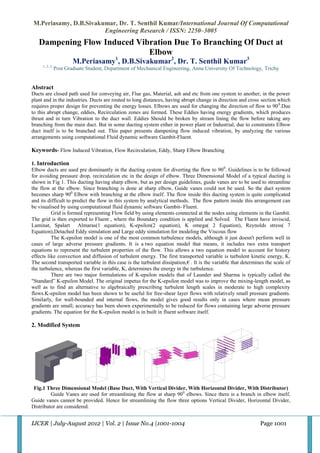
- 1. M.Periasamy, D.B.Sivakumar, Dr. T. Senthil Kumar/International Journal Of Computational Engineering Research / ISSN: 2250–3005 Dampening Flow Induced Vibration Due To Branching Of Duct at Elbow M.Periasamy1, D.B.Sivakumar2, Dr. T. Senthil Kumar3 1, 2, 3, Post Graduate Student, Department of Mechanical Engineering, Anna University Of Technology, Trichy Abstract Ducts are closed path used for conveying air, Flue gas, Material, ash and etc from one system to another, in the power plant and in the industries. Ducts are routed to long distances, having abrupt change in direction and cross section which requires proper design for preventing the energy losses. Elbows are used for changing the direction of flow to 90 0.Due to this abrupt change, eddies, Recirculation zones are formed. These Eddies having energy gradients, which produces thrust and in turn Vibration to the duct wall. Eddies Should be broken by stream lining the flow before taking any branching from the main duct. But in some ducting system either in power plant or Industrial, due to constraints Elbow duct itself is to be branched out. This paper presents dampening flow induced vibration, by analyzing the various arrangements using computational Fluid dynamic software Gambit-Fluent. Keywords- Flow Induced Vibration, Flow Recirculation, Eddy, Sharp Elbow Branching 1. Introduction Elbow ducts are used pre dominantly in the ducting system for diverting the flow to 900. Guidelines is to be followed for avoiding pressure drop, recirculation etc in the design of elbow. Three Dimensional Model of a typical ducting is shown in Fig 1. This ducting having sharp elbow, but as per design guidelines, guide vanes are to be used to streamline the flow at the elbow. Since branching is done at sharp elbow, Guide vanes could not be used. So the duct system becomes sharp 900 Elbow with branching at the elbow itself. The flow inside this ducting system is quite complicated and its difficult to predict the flow in this system by analytical methods. The flow pattern inside this arrangement can be visualised by using computational fluid dynamic software Gambit- Fluent. Grid is formed representing Flow field by using elements connected at the nodes using elements in the Gambit. The grid is then exported to Fluent , where the Boundary condition is applied and Solved. The Fluent have inviscid, Laminat, Spalart Almaras(1 equation), K-epsilon(2 equation), K omega( 2 Equation), Reynolds stress( 7 Equation),Detached Eddy simulation and Large eddy simulation for modeling the Viscous flow The K-epsilon model is one of the most common turbulence models, although it just doesn't perform well in cases of large adverse pressure gradients. It is a two equation model that means, it includes two extra transport equations to represent the turbulent properties of the flow. This allows a two equation model to account for history effects like convection and diffusion of turbulent energy. The first transported variable is turbulent kinetic energy, K. The second transported variable in this case is the turbulent dissipation,€ . It is the variable that determines the scale of the turbulence, whereas the first variable, K, determines the energy in the turbulence. There are two major formulations of K-epsilon models that of Launder and Sharma is typically called the "Standard” K-epsilon Model. The original impetus for the K-epsilon model was to improve the mixing-length model, as well as to find an alternative to algebraically prescribing turbulent length scales in moderate to high complexity flows.K-epsilon model has been shown to be useful for free-shear layer flows with relatively small pressure gradients. Similarly, for wall-bounded and internal flows, the model gives good results only in cases where mean pressure gradients are small; accuracy has been shown experimentally to be reduced for flows containing large adverse pressure gradients. The equation for the K-epsilon model is in built in fluent software itself. 2. Modified System Fig.1 Three Dimensional Model (Base Duct, With Vertical Divider, With Horizontal Divider, With Distributor) Guide Vanes are used for streamlining the flow at sharp 900 elbows. Since there is a branch in elbow itself, Guide vanes cannot be provided. Hence for streamlining the flow three options Vertical Divider, Horizontal Divider, Distributor are considered. IJCER | July-August 2012 | Vol. 2 | Issue No.4 |1001-1004 Page 1001
- 2. M.Periasamy, D.B.Sivakumar, Dr. T. Senthil Kumar/International Journal Of Computational Engineering Research / ISSN: 2250–3005 Vertical divider is placed parallel to the vertical axis, spaced equally by dividing the flow volume by fourth. Vertical divider is located 200 mm minimum away from the cavity. Horizontal divider is placed parallel to the Horizontal axis, spaced equally by dividing the flow volume by fourth. Horizontal divider is located 200 mm minimum away from the cavity. Both horizontal and vertical divider does not affect flow volume much since thickness face only opposes the flow. Distributor is located and staggered to vertical axis as in Figure. Distributor obstructs flow volume unlike in horizontal and vertical divider. Distributor also placed by maintaining 200 mm gap minimum from the cavity. 3. Results and Discussion Fig.2 Base Model Static Pressure Fig.3 Horizontal Divider Static Pressure Fig.4 Vertical Divider Static Pressure Fig.5 Distributor Static Pressure Pressure gradients as in Fig.2 creates eddies. The energy in eddies creates vibration on the duct wall. Horizontal Divider breaks the eddies to some extend as the velocity gradient decreases. Even Though vertical divider breaks the eddies to 90 percent as in Fig 5, there exist some low pressure zone. But in Distributor model the pressure distribution is uniform at the vibrating Zone as in Fig.5 IJCER | July-August 2012 | Vol. 2 | Issue No.4 |1001-1004 Page 1002
- 3. M.Periasamy, D.B.Sivakumar, Dr. T. Senthil Kumar/International Journal Of Computational Engineering Research / ISSN: 2250–3005 . Fig.6 Base Model Velocity Fig.7 Horizontal Divider Velocity Fig.8 Vertical Model Velocity Fig.9 Distributor Velocity The Velocity plot in the base model (Fig.6) illustrates recirculation zones (Velocity gradient at the section) in the vibrating zone. Horizontal Divider avoids recirculation zones only at few locations. Even though vertical divider avoids recirculation zones, Velocity becomes minimal at sharp corner. In Distributor plate velocity becomes maximum at Distributor section, and stream lined in further zones. 4. Conclusion: Three Dimensional Computational Fluid Dynamic analysis of Base Ducting, Modified horizontal Divider with base duct, Vertical divider with base duct, Distributor plate with Base duct was done using Gambit-Fluent for the turbulent intensity level of five, Ten, Fifteen and Twenty percent . From the analysis it is seen that Distributor plate breaks eddies and avoid recirculation zones. This pattern is repeated for all the turbulent intensity level of Five percent, Ten percent, Fifteen percent and Twenty percent. Further Distributor plate requires minimum material, easy to attach to the existing system. Hence Distributor plate model is selected. IJCER | July-August 2012 | Vol. 2 | Issue No.4 |1001-1004 Page 1003
- 4. M.Periasamy, D.B.Sivakumar, Dr. T. Senthil Kumar/International Journal Of Computational Engineering Research / ISSN: 2250–3005 References: [1] A. Leonard And A. Roshko , Aspects Of Flow-induced Vibration, Journal of Fluids and Structures (2001) 15, 415-425. [2] Peter Vasilyev, Leonid Fromzel,Published, Analytical Study of Piping Flow-induced Vibration. Example of Implementation, Transactions of the 17th International Conference on Structural Mechanics in Reactor Technology (SMiRT 17) Prague, Czech Republic, August 17 –22, 2003 [3] Y.S.Choy, J.Huang, L.Huang,Y.Zhou, An Experimental Study of Flow Induced Vibration on a Tensioned Membrane,Journal of Mechanical Science and Technology 21 (2007) 1359-1366. [4] Benny KUAN, William YANG ,Chris SOLNORDAL, CFD Simulation And Experimental Validation of dilute particulate turbulent flows in a 900 Duct Bend, Third International Conference on CFD in the Mineral and Process Industries CSIRO, Meibourne, Australia. [5] ArindamMandal, SomnathBhattecharjee, Rabin Debnath, Debasish Roy, SnehamoyMajumder, Experimental Investigation of Turbulent Fluid Flow through a Rectangular Elbow ,International Journal of Engineering Science and Technology Vol. 2(6), 2010, 1500-1506” [6] Bing Yang, FupingGao, Yingxiang Wu, Experimental Study on Flow Induced Vibration of a Cylinder with Two Degrees of Freedom Near a rigid Wall,Proceedings of the Eighteenth (2008) International Offshore and Polar Engineering Conference Vancouver, BC, Canada, July 6-11, 2008 “ [7] Stappenbelt B, Flow-induced vibration mitigation using attached splitter-plates , “2009 Annual Bulletin of the Australian Institute of High Energetic Materials v.l (20 I0) pp. 23-33 [8] S.Mittal, V.Kumar, Finite Element Study of Vortex-Induced Cross-Flow and in-Line Oscillations of Circular cylinder at Low Reynolds Number , International Journal for Numerical methods in Fluids,Int.J.Number.Meth.Fluids 31 : 1087-1120(1999) [9] R. T. FAAL, D. DERAKHSHAN , Flow-Induced Vibration of Pipeline on Elastic Support, The Twelfth East Asia-Pacific Conference on Structural Engineering and Construction , Procedia Engineering 14 (2011) 2986–2993” Available in Science Direct. [10] Ruth MOSSAD, William YANG, M. Philip SCHWARZ, NUMERICAL PREDICTION OF AIR FLOW IN A SHARP 90º ELBOW,Seventh International Conference on CFD in the Mineral and Process Industries CSIRO, Meibourne, Australia 9-11 December 2009”. [11] I.ChienLee,Kun Yu Chen, Jing Wang yu, Vibration reduction of the flue gas duct system on the site of TAICHUNG NO. 9 Power Plant ,18th Conference of the Electric Power supply Industry [12] Cyril M.Harris,Allan G.Piersol,R.D.Blevins, Harris’ Shock and Vibration Handbook, Mcgraw Hill, pp 29.1-29.67 IJCER | July-August 2012 | Vol. 2 | Issue No.4 |1001-1004 Page 1004