ماكينات المصاعد
•
3 likes•2,212 views

This document provides specifications for several industrial lifting machines: - The ISV-60 lifts loads from 50-100kg using a 1HP motor and travels 12m. - The IW-140 lifts up to 450kg with motors from 0.5-1HP and reductions from 41:1-58:1. - The IW-150 lifts up to 630kg with motors up to 1.6HP and reductions from 32:1-58:1. - Additional models listed include the IW-315, IW-190N, SC-140, and IS-85H, each specifying load capacities, speeds, motors, pulleys, and dimensions.

Recommended
Recommended
More Related Content
What's hot
What's hot (19)
Similar to ماكينات المصاعد
Similar to ماكينات المصاعد (20)
More from freemadoo
More from freemadoo (20)
Recently uploaded
Recently uploaded (20)
ماكينات المصاعد
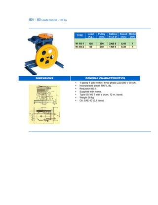
- 1. ISV - 60 Loads from 50 - 100 kg. TYPE Load (Kg.) Pulley (mm.) Cables N¼X Ø Speed (m/s) Motor (HP) W- 60-1 100 300 2XØ 6 0,40 1 W- 60-2 50 240 1XØ 6 0,30 1 DIMENSIONS GENERAL CHARACTERISTICS • 1 speed 4 pole motor, three phase 220/380 V 90 c/h. • Incorporated break 190 V. dc. • Reduction 60:1. • Supplied with frame. • Type ISV 60 T with a drum, 12 m. travel. • Weight 38 kg • Oil: SAE 40 (0,5 litres)
- 2. IW - 140 N 4, 5 and 6 TYPE W- 140 N Load (Kg.) Power (m/s) MOTOR Traction sheave (m.m.) Reduction iPower (CV) R.P.M. 1 320 0,63 4,5 1500 520 58:1 2 320 0,63/0,15 4,5 1500/375 520 58:1 3 320 0,80/0,20 4,5 1500/375 450 41:1 4 320 1,00/0,25 5,5 1500/375 520 41:1 7 400 0,63 5,5 1500 520 58:1 8 400 0,70/0,18 5,5 1500/375 550 41:1 9 400 0,80/0,20 5,5 1500/375 450 41:1 12 450 0,70/0,18 7,5 1500/375 550 58:1 14 450 0,63/0,15 5,5 1500/375 520 58:1 15 450 0,80/0,20 7,5 1500/375 450 41:1 16 450 1,00/0,25 7,5 1500/375 520 41:1 DIMENSIONS GENERAL CHARACTERISTICS • 1 and 2 speed motors, three phase 120 c/h. • Motofan for 180 c/h. • Reduction 60:1. • Voltage break 48, 60, 110, 125, 190 V dc. • Supplied with a metallic frame and buffers.. • Pulley with an external pad on bronze. • Approx. weight 270 kg, depending on type. • Oil: SAE 40 (2,5 litres). • Special motors for all assemblies and VVF. Maximum Load 450 kg Maximum power CV. 7,5 Maximum par 115 mkp. Maximum static load 2000 kgf.
- 3. IW - 150 N 4, 5, 6 and 8 TYPE W-150 N Load (Kg.) Rated Speed (m/s) MOTOR Traction sheave (m.m.) Reduc tion i Power (CV) R.P.M.. 1 A 450 0,50/0,1 0 4,5 1500/375 400 58:1 1 B 630 0,50/0,1 0 5,5 1500/375 400 58:1 2 A 400 0,63/0,1 5 4,5 1500/375 500 58:1 2 B 450 0,63/0,1 5 5,5 1500/375 500 58:1 2 C 630 0,63/0,1 5 7,5 1500/375 500 58:1 5 A 320 0,80/0,2 0 4,5 1500/375 500 45:1 5 B 400 0,80/0,2 0 5,5 1500/375 500 45:1 5 C 450 0,80/0,2 0 7,5 1500/375 500 45:1 5 D 630 0,80/0,2 0 10 1500/375 500 45:1 6 B 400 1,00/0,2 5 5,5 1500/375 600 45:1 6 C 450 1,00/0,2 5 7,5 1500/375 600 45:1 6 D 630 1,00/0,2 5 10 1500/375 600 45:1 7 B 320 1,00/0,2 5 5,5 1500/375 400 32:1 7 C 450 1,00/0,2 5 7,5 1500/375 400 32:1 8 C 400 1,20/0,3 0 7,5 1500/375 500 32:1 8 D 450 1,20/0,3 0 10 1500/375 500 32:1 9 C 320 1,40/0,4 0 7,5 1500/375 600 32:1 9 D 400 1,40/0,4 0 10 1500/375 600 32:1 11 D 450 1,60 10 VVVF 500 46:2 12 B 320 1,00 (2:1) 5,5 1500/375 600 46:2 12 C 450 1,00 (2:1) 7,5 1500/375 600 46:2 12 D 630 1,00 (2:1) 10 1500/375 600 46:2 13 E 450 1,50 (2:1) 11 VVVF 600 28:2 14 E 630 1,50 (2:1) 13 VVVF 600 28:2
- 4. 15 TD 320 0,50/0,1 0 10 1500/375 400 45:1 DIMENSIONS GENERAL CHARACTERISTICS • 2 speed motor, 120 c/h. • Motofan for 180 c/h. • Voltage break 48, 60, 110, 125, 190 V dc. • Supplied with a metallic frame and buffers. • Traction sheave with an extractable ring. • External pad on bronze. • Approx. weight 420 kg. depending on type. • Oil: SAE 40 (2.5 litres). • 4 pole motor for 1 speed and VVF. • Special motors, all voltages. • Motors VVF until 13 C.V. Maximum load 600 kg Maximum power CV. 10 Maximum par 153 mkp. Maximum static load 3500 kgf.
- 5. IW - 315 TYPE IW-315 Load (Kg.) Rated speed(m/s) MOTOR Traction sheave (m.m.) Reduction i Power (CV) R.P.M. 1 1000 1,00/0,25 15 1500/375 620 49:1 2 1000 1,60 20 VVVF 480 49:2 3 1000 2,00 24 VVVF 620 49:2 4 1250 1,00/0,25 17 1500/375 620 49:2 5 1250 1,60 24 VVVF 480 49:2 6 1250 2,00 30 VVVF 620 49:2 7 1500 0,50/0,10 12 1500/375 480 67:1 8 1500 0,70/0,20 15 1500/375 620 67:1 9 1500 1,00/0,25 20 1500/375 620 49:1 10 1500 1,60 27 VVVF 480 49:2 11 1500 2,00 34 VVVF 620 49:2 12 1750 0,50/0,10 15 1500/375 480 67:1 13 1750 0,70/0,20 17 1500/375 620 67:1 14 1750 1,00/0,25 24 1500/375 620 49:1 15 1750 1,60 33 VVVF 480 49:2 16 1750 2,00 40 VVVF 620 49:2 17 2000 0,50/0,10 15 1500/375 480 67:1 18 2000 0,70/0,20 20 1500/375 620 67:1 19 2000 1,00/0,25 28 1500/375 620 49:1 20 2000 1,60 37 VVVF 480 49:2 21 2000 2,00 46 VVVF 620 49:2 22 2250 0,50/0,10 17 1500/375 480 67:1 23 2250 0,70/0,20 22 1500/375 620 49:1 24 2250 1,00/0,25 30 1500/375 620 49:1 25 2250 1,60 42 VVVF 480 49:2 26 2500 0,50/0,10 17 1500/375 480 67:1 27 2500 0,70/0,20 24 1500/375 620 67:1 28 2500 1,00/0,25 34 1500/375 620 49:1 29 2500 1,60 46 VVVF 480 49:1
- 6. DIMENSIONS GENERAL CHARACTERISTICS • Asynchr. motor mounting shapes B9-B3, 2 speed, 120 c/h. • Motors for VVVF up to 46 CV. • Suplementary fan for 180 c/h (optional). • Brake: 220 V c.a. • Oil: ISO - 150 EP (30 litres). • Traction pulley with extractable ring and outboard support over bearings. Maximum power 46 CV en VVVF Maximum static load 12.000 Kgf. Maximum load 2.500 Kg Maximum par 515 mkp.
- 7. IW - 190 N 8, 10, 12, 15, 18 and 20 TYPE W-190 N Load (Kg.) Rated speed(m/s) MOTOR Traction sheave (m.m.) Reduction i Power (CV) R.P.M. 1 A 1000 0,60/0,10 12 1500/375 480 60:1 1 B 1250 0,60/0,10 15 1500/375 480 60:1 3 B 1000 0,80/0,20 15 1500/375 480 42:1 3 C 1350 0,80/0,20 17 1500/375 480 42:1 3 D 1500 0,80/0,20 20 1500/375 480 42:1 4 A 750 1,00/0,25 12 1500/375 570 42:1 4 B 1000 1,00/0,25 15 1500/375 570 42:1 4 D 1125 1,00/0,25 20 1500/375 570 42:1 4 E 1350 1,00/0,25 24 1500/375 570 42:1 5 B 630 1,30/0,55 15 1500/375 480 52:2 5 C 750 1,30/0,55 17 1500/375 570 52:2 5 D 1000 1,30/0,55 20 1500/375 480 52:2 5 E 1125 1,30/0,55 24 1500/375 480 52:2 6 C 630 1,60/0,85 17 1500/375 570 52:2 6 D 750 1,60/0,80 20 1500/375 570 52:2 6 E 1000 1,60/0,85 24 1500/375 570 52:2 8 D 630 2,00/0,55 20 1500/375 570 41:2 8 E 750 2,00/0,55 24 1500/375 570 41:2 9 B 750 1,60 (2:1) 15 VVVF 710 37:2 9 E 1100 1,60 (2:1) 24 VVVF 710 37:2 DIMENSIONS GENERAL CHARACTERISTICS • 2 speed motor 120 c/h. • Motofan for 180 c/h. • Voltage breaks 48, 60, 110, 125, 190 V dc. • Supplied with a metallic frame and buffers. • Traction sheave with an extractable ring. • External pad on bronze. • Approx. weight 680 kg. depending on type. • Oil: SAE 40 (5 litres). • 4 Pole motor for 1 speed and VVF. • Special motors, all voltages. • Motors VVF until24 C.V. Maximum load 1500 kg Maximum power CV. 24 Maximum par 250 mkp. Maximum static load 6000 kgf.
- 8. SC - 140 TYPE W-190 N Load (Kg.) Rated speed(m/s) MOTOR Traction sheave (m.m.) Reduction iPower (CV) R.P.M. 1 320 0,63 4,5 1500 320 41:1 2 320 0,70 4,5 1500 370 41:1 3 320 0,86 4,5 1500 320 29:1 4 320 1,00 4,5 1500 370 29:1 5 450 0,63 5,5 1500 320 41:1 6 450 0,70 5,5 1500 370 41:1 7 450 0,86 5,5 1500 320 29:1 8 450 1,00 5,5 1500 370 29:1 9 630 0,63 6 1500 320 41:1 10 630 0,70 6 1500 370 41:1 11 630 0,86 7,5 1500 320 29:1 12 630 1,00 7,5 1500 370 29:1 13 320 0,80 (2:1) 5,5 1500 320 30:2 14 320 1,00 (2:1) 5,5 1500 370 30:2 15 450 0,80 (2:1) 6 1500 320 30:2 16 450 1,00 (2:1) 7,5 1500 370 30:2 17 630 0,80 (2:1) 7,5 1500 320 30:2 18 630 1,00 (2:1) 9 1500 370 30:2 DIMENSIONS GENERAL CHARACTERISTICS • Motors for VVVF up to 9 CV. • Machine for roomless • Horizontal o vertical positions machine • Electric rescue • Weight approximate 180 kg. (aprox.) • Metal bedframe and outboard support optionals. • Suplpy with protector of pulley Maximum power 9 CV en VVF Maximum static load 2.500 Kgf. Maximum load 630 Kg. Maximum par 130 mkp.
- 9. IS - 85 H Loads from 100 - 200 kg. TYPE IS 85 H Load (Kg.) Pulley (mm.) Cables N¼X Ø Speed (m/s) Motor (HP) 1 150 Ø 300 2XØ 6 0,40 1,5 Mono. 2 200 Ø 300 2XØ 6 0,40 2,5 Tri. 3 100 Ø 240 1XØ 8 0,30 1,5 Mono. 4 200 Ø 240 1XØ 8 0,30 2,5 Tri DIMENSIONS GENERAL CHARACTERISTICS • 1 speed motor, one phase 1,5 CV and three phase 2,5 CV. • Incorporated break 190 V. dc. • Reduction 60:1. • Supplied with frame . • Weight 52 kg. • Oil: SAE 40 (0,5 litres).
- 10. General An elevator system with its hoistway, machine room, and waiting lobbies is a major element in a building and requires special design consideration. Preengineered or custom-made elevator systems can be constructed to meet virtually all vertical transportation needs for passenger, freight, or service. In all cases, design of an elevator system must be carefully considered throughout all stages of the building design process. During initial stages, the elevator handling capacity and quality of service desired determines the size, speed, number, type, and location of elevator systems. Proper selection depends on type of tenancy, number of occupants, and the building design (number of floors, floor heights, building circulation, etc.). Elevator Arrangement locates the elevator within the building plan to provide efficient and accessible service. Each elevator system, once selected, requires Operational Spaces, hoistway pit and machine room, and Passenger Spaces, lobby, and elevator car. Proper planning and contact with representatives of the elevator industry and local code officials are essential to each of these design areas. The two most common systems, the Hydraulic Elevator and the Electric Elevator, are shown in the drawings "Hydraulic Elevator" and "Electric Elevator." The systems are distinguished mainly by their hoisting mechanisms. The Hydraulic Elevator uses an oil hydraulic driving machine to raise and lower the elevator car and its load. A hydraulic pump unit is one in which the energy is applied by means of a liquid under pressure in a cylinder equipped with a plunger or piston. The car is supported at the pit floor (hoistway base). Lower speeds and the piston length restrict the use of this system to approximately 55 ft. It generally requires the least initial installation expense, but more power is used during operation because of the greater loads imposed on the driving machine. An Electric Elevator is a power elevator where the energy is applied by means of an electric driving machine. In the electric driving machine the energy is applied by an electric motor. It includes the motor, brake, and the driving sheave or drum together with its connecting gearing, if any. Medium to high speeds and virtually limitless rise allow this elevator to serve high-rise, medium-rise, and low-rise buildings.
- 11. Machine Room (Electric Elevators) Normally located directly over the top of the hoistway — it could also be below at side or rear — the machine room is designed to contain elevator hoisting machine and electronic control equipment. Adequate ventilation, soundproofing, and structural support for the elevator must be considered. Requires self-closing, self-locking access door. Local codes may require that no other electrical or mechanical equipment, not associated with the elevator, be installed in the machine room. Elevator Car Guided by vertical guide rails on each side of the car, the elevator car conveys passenger or freight between floors. It consists of a car constructed within a supporting platform and frame. Design of the car focuses on the finished ceiling, walls, floor, and doors with lighting, ventilation, and elevator signal equipment. The car and frame of a hydraulic elevator system are supported by a piston or cylinder. The car and frame of an electric elevator system are supported by the hoist machine. The elevator and its counterweight are connected via steel ropes. Hoistway The hoistway is a vertical shaft for the travel of one or more elevators. It includes the pit and terminates at the underside of the overhang machinery space floor for electric elevators, or at the underside of the roof over the hoistway of a hydraulic elevator. Access to the elevator car and hoistway is normally through hoistway doors located at each floor serviced by the elevator system. Hoistway design is determined by the characteristics of the elevator system selected and by requirements of the applicable code for fire separation, ventilation, soundproofing, or nonstructural elements. Lobby Elevator waiting areas are designed to allow free circulation of passengers, rapid access to elevator cars, and clear visibility of elevator signals. All elevator lobbies must be enclosed with the exception of the designated main building entry level. Accessibility Passenger elevators on accessible routes should comply with requirements of ANSI 117.1 and ADAAG. Machine Room (Hydraulic Elevator) Normally located near the base of the hoistway, the machine room contains hydraulic pump unit and electronic controls. Provisions of adequate ventilation and soundproofing must be considered. Requires self-closing, self-locking access door. Local codes may require that no other electrical or mechanical equipment, not associated with the elevator, be installed in the machine room.
- 15. Residential Elevators Typical car sizes, A x B: 36 in. x 36 in., 42 in. x 42 in., 36 in. x 48 in. 12 sq ft platform maximum size allowed by National Elevator Code for residential elevators, ANSI A17.1. This platform size does not meet the National Handicapped Access Code, ANSI A117.1, for use by an unassisted wheelchair-bound person. Load capacity of drum-type machine is 450 lb. Speed is 30 ft per minute. Load capacity of traction machine is 700 lb. Speed is 36 ft per minute. Elevators operate on 220/230 volt, single phase power supply. A disconnect switch must be provided within sight of the machine. A 110V, single phase power supply is required for lighting of machine area of hoistway. Enclosures are recommended for all hoistways. Fire rating of hoistway enclosure and access doors must be consistent with the fire rating of the building construction. See local codes. Notes 1. Dimensions may vary among manufacturers and according to the system selected. Elevators carrying greater loads or operating at higher speeds require more clearance overhead and in pit areas. 2. Elevator cars may have higher interior clearance if desired, which increases overhead clearance required in the hoistway. 3. Guide rails usually are provided by the manufacturer in 5 ft sections. Some manufacturers supply rails that can span from floor structure to floor structure. If the existing structure cannot support the guide rails, manufacturers can provide a self-supporting tower that transmits the load to its base. Increased horizontal clearance in the hoistway is required. If a third guide rail is required, it is supplied in 3 ft 4 in. sections. 4. Dimensions given are appropriate for most applications. For exact dimensions required in specific circumstances, consult manufacturers. 5. Elevator cars can be provided with openings on two sides; guide rails must be located accordingly. Consult manufacturers. Dumbwaiters Typical car sizes, A x B: 24 in. x 24 in., 30 in. x 30 in., 36 in. x 36 in., 30 in. x 48 in. Smaller sizes available. 9 sq ft platform maximum size allowed by National Elevator Code for dumbwaiters, ANSI A17.1. 48 in. high car is maximum allowed by National Elevator Code for dumbwaiters, ANSI A17.1. Load capacity for drum-type machines is 500 lb. Speed is 50 ft per minute. Drum-type machines are not recommended for installations with total travel of more than 36 ft–40 ft. Maximum total travel 50 ft. Load capacity of traction machines is 500 lb. Speeds to 500 ft per minute are available. Dumbwaiters require 3 phase electrical power. For exact voltage consult manufacturer.
- 16. Notes 1. Dimensions may vary among manufacturers and according to system selected. Dumbwaiters carrying greater loads or operating at higher speeds require more clearance overhead and in pit areas. 2. Guide rails usually are provided by the manufacturer in 5 ft sections. Some manufacturers supply rails that can span from floor structure to floor structure. If existing structure cannot support the guide rails, manufacturers can provide a self-supporting tower that transmits the load to its base. Increased horizontal clearance in the hoistway is required. 3. Vertical dimensions given assume the use of vertical bi-parting doors. The entire door may slide up and down; however, required clearances will vary. Swing hoistway doors also are available. Consult manufacturers.
- 18. Elevator Selection—Hospital The accompanying diagram illustrates elevator selection parameters in the context of a hospital layout. Actual calculations relating these parameters are complex. Consultation with an elevator industry representative or consulting elevator engineer is recommended. 1. BUILDING HEIGHT: Floor-to-floor height and number of floors. 2. BUILDING POPULATION: Total number of building occupants and expected visitors and their expected distribution throughout the building. 3. BUILDING USE ANALYSIS: Location of offices, patients' rooms, service areas, and ancillary spaces conducive to mass assembly. Primary public circulation areas and primary staff circulation areas should be identified. 4. WAITING AREA: Peak loading and waiting time are two important concepts in providing the quality of elevator service expected by hospital visitors and staff. Different standards are applied according to building use. Consult an elevator engineer. 5. LOCATION OF MAJOR ENTRANCES 6. ELEVATOR SYSTEMS: A large selection of elevator capacities, speed, controls, and type are available. In this case, passenger and service elevators are shown. An elevator with a front and rear entrance serves as a passenger elevator during peak visiting hours. The wide variety of elevator alternatives should be discussed with an elevator engineer to select the system most suitable for each individual situation. SERVICE REQUIREMENTS: Elevators must have sufficient capacity and speed to meet building service requirements. In this case, the elevator must accommodate a 24 x 76 in. ambulance type stretcher with attendants. Check local requirements. For patient service in hospitals, to accommodate beds with their attachments, use 5000 lb elevators; platforms 6 ft wide x 9 ft 6 in. deep, doors at least 4 ft wide (4 ft 6 in. width is preferred). CODE AND REGULATIONS: Recommendations and code restrictions regarding accessibility, fire safety, elevator controls, and so on, may affect elevator selection. Consult with an elevator industry representative or consulting elevator engineer. As a minimum, comply with the ANSI A17.1 for Elevators, Dumbwaiters, Escalators and Moving Walks. NOTE: Elevators should not be considered as emergency exits. Elevator Systems In Buildings Other Than Private Homes Selection of elevator systems increases in complexity with the size and complexity of the project. Even though the vertical transportation needs of low-rise residential and commercial projects may be simply met, all the parameters listed below should be considered and analyzed with a consulting elevator engineer to ensure proper selection. Building Population The elevator selection process must begin with a thorough analysis of how people will occupy the building. 1. TOTAL POPULATION AND DENSITY: The total number of occupants and visitors and their distribution by floors within a building.
- 19. 2. PEAK LOADING: Periods when elevators carry the highest traffic loads. For example, peak loading in office buildings coincides with rush hours and/or lunch periods, while peak loading in hospitals may occur during visiting hours. 3. WAITING TIME: The length of time a passenger is expected to wait for the next elevator to arrive. These demands vary according to building use and building occupant expectations. A person willing to wait 50–70 sec in an apartment building may be willing to wait only 20–25 sec in an office building. 4. DEMAND FOR QUALITY: Sophistication of controls and elevator capacity may be varied to cater to the expected taste of passengers. Large elevator cars and the smooth, long life operation of a gearless elevator may convey an image of luxury even if a small elevator having a less sophisticated system would be technically sufficient. Building Characteristics Physical building characteristics are considered together with population characteristics to determine size, speed, type, and location of elevator systems. 1. HEIGHT: The distance of elevator travel (from lowest terminal to top terminal), number of floors, and floor height. 2. BUILDING USE ANALYSIS: Location of building entrance areas of heavy use such as cafeteria, restaurant, auditorium, and service areas must be identified. Typically, a building should be planned to ensure that no prospective passengers must walk more than 200 ft to reach an elevator. Elevator Systems And Regulations The parameters previously described outline the environment in which the elevator operates. Local code regulations and ANSI A17.1 requirements provide further elevator guidelines. Available elevator systems are analyzed to ensure that suitable speed, capacity, controls, and number of cars are selected.
- 22. Notes Medium -and high-rise buildings utilize ELECTRIC GEARED TRACTION and ELECTRIC GEARLESS TRACTION elevator systems. The main difference between the two systems lies in the hoisting machinery. General design considerations involving hoistway, machine room, and elevator planning are similar. ELECTRIC GEARLESS TRACTION ELEVATOR systems are available in preengineered units with speeds of 500 to 1200 fpm. Systems with greater speeds are also available.
- 23. Gearless elevators, when used in conjunction with appropriate electronic controls, offer the advantages of a long life and smoothness of ride. ELECTRIC GEARED TRACTION ELEVATOR systems are designed to operate within the range of 100 to 350 fpm, which restricts their use to medium-rise buildings. Both geared and gearless drive units are governed by electronic CONTROLS, which coordinate car leveling, passenger calls, collective operation of elevators, door operation, car acceleration and deceleration, and safety applications. A broad range of control systems are available to meet individual building requirements. STRUCTURAL REQUIREMENTS call for the total weight of the elevator system to be supported by the MACHINE BEAMS and transmitted to the building (or hoistway) structure. Consult with elevator consultants and structural engineers. If the elevator machine is to be supported solely by the machine room floor slab, the floor slab shall be designed in accordance with the requirements of ANSI A17.1. Check local codes for required fire enclosures.
- 28. General Notes Low-rise buildings may use either oil hydraulic or electric elevator systems. Elevator selection, arrangement, and design of lobby and cars are similar in both cases. The primary differences between the two systems are in their operational requirements. The hydraulic elevator system is described below; the electric elevator system on the next page. The major architectural considerations of the hydraulic elevator are the machine room, normally located at the base, and the hoistway serving as a fire protected, ventilated
- 29. passageway for the elevator car. Adequate structure must be provided at the base of the hoistway to bear the load of the elevator car and its supporting piston or cylinder. Generally speaking, oil hydraulic elevators are used in applications requiring limited vertical travel usage and low speed.
- 34. General Wheelchair lifts are suitable for retrofits of buildings that are not barrier free. Bridges are available from manufacturers for installation over stairs. Recommended speed:10 to 19 fpm. Capacity: 500 to 750 lb. Lifts operate on standard household current and are suitable for interior or exterior applications.
- 36. Inclined stair lifts can be adapted to straight run and spiral stairs. Standard types run along guide rails or tubes fastened to solid wall, stairs, or floor structure. Power units may be placed at the top or bottom of the lift run or in the lift chassis, depending on the manufacturer. Some inclined lift systems fold up out of the way for daily stair use. Where stair width necessitates a more compact lift, as in residential use, chair lifts are available for straight run or spiral stairs. However, many inclined stair lifts come with standard fold-down seats. Recommended speed, 20 to 25 fpm on straight runs, 10 fpm on curved sections. Capacity, 500 lb. Typical platform size, 30 x 40 in. Check local code capacities.
- 41. General An Area of Rescue Assistance (ARA) is defined in the Americans with Disabilities Act Accessibility Guidelines (ADAAG) as "an area, which has direct access to an exit, where people who are unable to use stairs may remain temporarily in safety to await further instructions or assistance during emergency evacuation." ARAs are also known as "Area for Evacuation Assistance" in the Uniform Building Code and as "Area of Refuge" in NFPA 101 and CABO/ANSI A117.1—1992. Note the exception in ADAAG section 4.1.3(9) for facilities having a supervised automatic sprinkler system. ADAAG does not require ARAs in alterations or existing facilities. These seven case studies provide examples of several ways to configure the ARA to meet ADAAG and UBC requirements. They provide a starting point for designing facilities and meeting the requirements of building officials. Verify design for compliance with local and state building codes. The ADA requires that the design of ARAs satisfy the building official having jurisdiction over the project. The ARA provisions in ADAAG were modeled after similar requirements in the 1991 edition of the UBC. The order of case studies corresponds to the seven options under ADAAG section 4.3.11.1. Legend A. Wheelchair space: 30 x 48 in. Minimum of two required with one per 200 occupants served by the ARA. B. "Area of Rescue Assistance" sign with symbol of accessibility, illuminated if required for exit signs. Directional signs are also required. C. Audible and visual two-way communication unit. D. Instructions on use of space.
- 42. Note 4 ft 0 in. dimension at stair is clear between handrails (typical).
- 60. General Note Thresholds are available in bronze and aluminum with a wide selection of shapes and dimensions.