Reacteur BWR Fukushima
•
1 like•1,219 views

The document provides basic design information about BWR3 and BWR4 reactors, which are the types used at the Fukushima Daiichi nuclear power plant. It describes the Mark I containment system, typical reactor vessel configurations, and the reactor core isolation cooling system. It then summarizes the events at Fukushima Daiichi following the 2011 earthquake and tsunami, including loss of cooling, hydrogen explosions, fuel damage in reactors 1-3, and challenges with spent fuel pools.

Recommended
More Related Content
What's hot
What's hot (20)
Viewers also liked
Viewers also liked (20)
Similar to Reacteur BWR Fukushima
Similar to Reacteur BWR Fukushima (20)
More from François Avril
More from François Avril (20)
Recently uploaded
Recently uploaded (20)
Reacteur BWR Fukushima
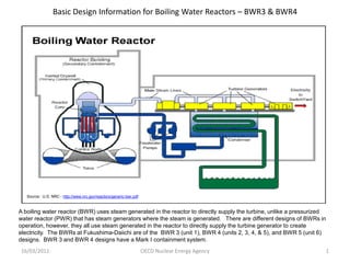
- 1. Basic Design Information for Boiling Water Reactors – BWR3 & BWR4 Source: U.S. NRC - http://www.nrc.gov/reactors/generic-bwr.pdf A boiling water reactor (BWR) uses steam generated in the reactor to directly supply the turbine, unlike a pressurized water reactor (PWR) that has steam generators where the steam is generated. There are different designs of BWRs in operation, however, they all use steam generated in the reactor to directly supply the turbine generator to create electricity. The BWRs at Fukushima-Daiichi are of the BWR 3 (unit 1), BWR 4 (units 2, 3, 4, & 5), and BWR 5 (unit 6) designs. BWR 3 and BWR 4 designs have a Mark I containment system. 16/03/2011 OECD Nuclear Energy Agency 1
- 2. BWR3 & BWR4 – Containment Configuration, typical for Fukushima-Daiichi Units 1, 2, 3, & 4 The Mark I Containment, shown here, consists of a drywell housing the reactor vessel and associated equipment, and a toriodial shaped wetwell. The Fukushima Daiichi: Location of Explosions in Containment includes both Units 1 and 3, location of the drywell and wetwell and fires in Unit 4. The is comprised of a steel liner explosion in Unit 2 occurred somewhere in with a surrounding concrete Spent the reactor building near structure. A secondary fuel the suppression containment structure, or pool chamber. reactor building, surrounds the primary containment. The reactor building is maintained at a slight negative pressure during normal operations. The top most part of the reactor building houses the refueling floor. The spent fuel pool is located within the reactor building. The explosions in Fukushima-Daiichi unit 1 occurred in the upper part of Source: U.S. NRC - http://www.nrc.gov/reactors/generic-bwr.pdf the reactor building in the spent fuel pool. In this location of the reactor building, the outer shell is typically made of sheet metal panels. At unit 3, the initial explosion was in the same area. At unit 2, the explosion occurred lower in the reactor building, near the suppression chamber. 16/03/2011 OECD Nuclear Energy Agency 2
- 3. BWR3 & BWR4 – Typical Reactor Vessel and Internals Configuration Within the reactor vessel are the fuel, control rods, jet pumps, moisture separators, and steam dryers. The control rods are inserted into the core from the bottom. At Fukushima-Daiichi, all 3 of the operating units automatically shutdown immediately following the earthquake with the control rods being inserted into the core. At this point, the heat being generated within the reactor is no longer from the fission process, but is primarily due to the radioactive decay of fission products (decay heat). So, unlike Chernobyl where the reactor was operating (fission process was still ongoing), at Fukushima-Daiichi, the reactors where shutdown and cooling is only needed to remove decay heat which is a small fraction of normal operating power. For about 1 hour after the earthquake and the loss of offsite electrical power, the emergency diesel generators (EDGs) were operating and providing electrical power to the systems for decay heat removal. At about that time, the tsunami struck the site and the EDGs stopped working. This was likely due to the failure of the fuel supply to the EDGs. With the loss of the EDGs, cooling to the fuel in the core was being provided by the reactor core isolation cooling (RCIC) system. Source: U.S. NRC – Boiling Water Reactor GE BWR/4 Technology Advanced Manual Chapter 6.0 16/03/2011 OECD Nuclear Energy Agency 3
- 4. BWR3 & BWR4 – Typical Reactor Core Isolation Cooling System The RCIC system uses steam generated in the reactor from the decay heat to power a turbine driven pump. The pump is supplied with water initially from a condensate storage tank (CST). The water for the CST is injected into the core through the feedwater line. Once the CST is drained, the suction of the RCIC pump is switched to the suppression pool where there is another large source of water. It appears that this system provided decay heat removal for about 7 hours after the reactors where shutdown following the earthquake. Typically, electrical power for the motor operated valves is provided by onsite batteries. Another concern is the buildup of pressure within the reactor vessel due to the increase in temperature from reduced cooling water flow. As the pressure increases, it can be controlled using the safety relief valves. However, the water inventory lost needs to be made up again in order to keep the fuel covered with water. Without electrical power to provide a source of water to the reactor vessel, the level in the reactor vessel decreased and eventually the fuel became uncovered. Once the fuel is uncovered, fuel damage can occur as a result of high temperatures and reactions between the cladding (zirconium based metal tubes surrounding the fuel pellets) and the steam being generated by the decay heat. This cladding-steam reaction also generates large amounts of hydrogen. Source: U.S. NRC – Boiling Water Reactor GE BWR/R Technology Advanced Manual Chapter 6.0 16/03/2011 OECD Nuclear Energy Agency 4
- 5. Fukushima-Daiichi Nuclear Power Plant Information The pressure from the reactor vessel was relieved into the suppression pool. This caused the temperature of the water and the pressure in the suppression pool to increase. However, without electrical power, there was no way to cool the water in the suppression pool and the pressure inside the primary containment began to increase. In order to minimize the potential for damage to the primary containment, the decision was made to vent the primary containment to the reactor building. Normally, this venting would occur through the ventilation system to the standby gas treatment system and vented through the site stack. However, it appears that the non-condensible gases and hydrogen were vented into the reactor building. In units 1 and 3 the hydrogen collected in the upper portions of the reactor building. This resulted in the large explosions and significant damage to the upper structures of the reactor building (secondary containment). In unit 2, it appears that the hydrogen collected in the reactor building closer to the suppression pool and the explosion that occurred at unit 2 has likely caused damage to the suppression pool and primary containment. In order to begin to recover the level in the reactor vessels of units 1, 2, and 3, the decision was made to inject seawater into the reactor vessels. This procedure is typically part of the emergency plans and is used when other sources of fresh water are no longer available for cooling and inventory makeup. Injection of seawater into the reactor vessels of all three units continues as a measure to provide cooling water to the fuel and to keep the fuel covered with water. Based on the information that is available, it appears that there has been fuel damage at Fukushima-Daiichi units 1, 2, and 3. Further, there has been structural damage to the reactor buildings (secondary containment) at units 1, 2, 3, and 4. The primary containment at unit 1 appears to be intact (no damage). However, it appears as a result of the explosions at units 2 and 3, damage to the primary containment (likely near the suppression pool) has occurred. Due to the fuel damage, there have been increases in radiation levels within the plant boundary and significantly higher than normal radiation levels have been detected offsite. In addition to the concerns with the fuel in the reactors at units 1, 2, and 3, the fuel in the spent fuel pools (SFPs) at all 6 of the units can be challenged if water is not put into the pools to make up the level as water is evaporated from the pools as it cools the fuel stored there. With limited electrical power onsite, it is difficult to makeup water to the SFPs using normal methods. Emergency measures to makeup inventory to the SFPs is further hampered by the extensive damage to the reactor buildings and the high radiation levels. There is little information on the status of the SFPs of units 1, 2, and 3, however, the fuel in these SFPs has had longer to decay than the fuel in the SFPs for units 4, 5, and 6 (which were in outages and defueled – all the fuel in the SFP – before the earthquake occurred). The water level in the unit 4 SFP is very low and fuel damage is suspected. The water level in the unit 5 and 6 SFPs is still covering the fuel, but the temperature of the water is increasing. Efforts are in progress to add water to the SFPs to maintain the fuel covered. 16/03/2011 OECD Nuclear Energy Agency 5
- 6. Fukushima-Daiichi Nuclear Power Plant Information Unit 6 Unit 5 Unit 1 Unit 2 Unit 3 Unit 4 Source: Tokyo Electric Power Company 16/03/2011 OECD Nuclear Energy Agency 6