SlideShare a Scribd company logo
1 of 15
Download to read offline
SITRAIN Training for
Automation and Industrial Solutions Page 1
NC-84D-HP
Tool Offset and Measuring
SITRAIN
NC-84D-HP /Tool Offset and Measuring Page 1
Automation and Drives
1/2008
© Siemens AG 2008 - All rights reserved
Tooloffset and Measuring
0 ca.X100 X200
Content Page
Tool data .......................................................................................................................................... 3
Tool Offset Variables ........................................................................................................................ 4
Read/Change Tool Offsets in the NC Program ................................................................................. 5
Comparing the Different Tool Data Management Types .................................................................... 6
Fine Offsets Relative to Location ...................................................................................................... 7
Mirroring the Tool Geometry ............................................................................................................ 8
Program Commands for Tool Management ...................................................................................... 9
Program Runtime (from Software V.6) .............................................................................................. 10
Workpiece Counter (From Software V.6) .......................................................................................... 11
Measurement, MEAS, MEAW .......................................................................................................... 12
Exercise - Measuring ....................................................................................................................... 13
Axial Measurement Functions MEASA, MEAWA .............................................................................. 14
Continuous measurement MEAC in the FIFO ................................................................................... 15
SITRAIN Training for
Automation and Industrial Solutions Page 2
NC-84D-HP
Tool Offset and Measuring
SITRAIN Training for
Automation and Industrial Solutions Page 3
NC-84D-HP
Tool Offset and Measuring
Structure of the offset memory
Every data set can be invoked with a T and D number; in addition to the
geometrical data for the tool, it contains other information such as the tool type.
Altogether max. 600 data sets per NCU. (From software V.5 max.1500)
depending on setting in $MN_MM_NUM_CUTTING_EDGES_IN_TOA and max.
9 data sets per tool. (From software V.5 max.12) depending on setting in MD
18106
Several entries exist for the geometric variables (e.g., length 1 or radius). These
are added together to produce a value (e.g. total length 1, total radius) which is
then used for the calculations.
Exception: In $MC_TOOL_PARAMETER_DEF_MASK geometry value (from
software V.5.3) and wear value of the facing axis can be switched to diameter
for turning operations.
The "reserved" parameters are only taken into account for 3D tool compensation
(CUT3DC, CUT3DF) and grinding tools.
SITRAIN
NC-84D-HP /Tool Offset and Measuring Page 3
Automation and Drives
1/2008
© Siemens AG 2008 - All rights reserved
Tool data
SITRAIN Training for
Automation and Industrial Solutions Page 4
NC-84D-HP
Tool Offset and Measuring
Data set structure
Reserved25
For turningclearance angle24
Applicant (z in G17)Length 112
Ordinate (y in G17)Length 213
Abscissa (x in G17)Length 314
Technology
Abscissa (x in G17)Length 323
Ordinate (y in G17)Length 222
Applicant (z in G17)Length 121
For drills not neededRadius15
End radius for CUT3DReserved16
Reserved17
Reserved18
Reserved19
cone angle for CUT3DReserved20
Base/ Holder
cone angle for CUT3DReserved11
Reserved10
Reserved9
Wear
Reserved8
End radius for CUT3DReserved7
For drills not neededRadius6
Abscissa (x in G17)Length 35
Ordinate (y in G17)Length 24
Applicant (z in G17)Length 13
Geometry: length & radius corrections
For turningCutting edge position2
Tool type1
NotesMeaningTool
parameter
Tool parameter are store in system variables
of form $TC_DPn[i,j]
$TC_DP1[2,3]
T2
D3
SITRAIN Training for
Automation and Industrial Solutions Page 5
NC-84D-HP
Tool Offset and Measuring
The modified values only take effect the next time T or D is programmed -
even when changed by the operator!
From Software V.5 Any changes the operator makes to the tool offset and zero offset in NC STOP
are effective and implemented immediately after a new NC START if MD9440=1
Delete Contours: $TC_DP1 [1, 6] =0 Deletes T1 D6
$TC_DP1 [3, 0] =0 Deletes T3 completely
$TC_DP1 [0, 0] =0 Deletes complete tool memory
The current (selected) offset values can also be read in the system variables:
Caution When these system variables are accessed there is no implicit preprocessing
stop.
With time-critical program sections you therefore need to program STOPRE
first.
"Flat" Tool Offsets(from software V. 4)
In contrast with the standard setting described until now
($MN_MM_TYPE_OF_CUTTING_EDGE=0) it is also possible to assign D
numbers that are not connected to the T numbers, e.g. when the tool
management is conducted externally.
D1 ... D32000 (max. 1500 numbers dep. on memory configuration)
Addressing the Parameters: $TC_DP1 [Dn] . .. $TC_DP25 [Dn]
Delete "Flat" Tool $TC_DP1 [6] =0 Deletes D6
Offsets $TC_DP1 [0] =0 Deletes complete tool memory
SITRAIN
NC-84D-HP /Tool Offset and Measuring Page 5
Automation and Drives
1/2008
© Siemens AG 2008 - All rights reserved
Read/Change Tool Offsets in the NC Program
Programming exercise:
N10 R1=$TC_DP3[4,1] reads L1 from T4 D1
N20 $TC_DP12[4,1]= $TC_DP12[4,1]-0.051 changes L1 wear
Active tool radius overall$O_TOOLR
Active tool length overall
m: length 1…3
$P_TOOLL[m]
Active correction
n: parameter number 1…25
$P_AD[n]
Active cutting edge (D- No.)$P_TOOL
Active tool number (T- No.)$P_TOOLNO
Content of system variablesName
SITRAIN Training for
Automation and Industrial Solutions Page 6
NC-84D-HP
Tool Offset and Measuring
Comparing the Possible Tool Data Management Types
To software V.3 only "deep" structures: offset call with "T123"
From software V.4 in addition "flat direct" structure is possible: offset call with "D32000"
From software V.5 in addition "flat indirect" structure is possible: offset call of D123 with "D5"
9 D numbers in PLC DBB...
From software V.5 with "deep" structure max. 12 cutting edges per tool, where D number and
cutting edge number CE= are separated. You can check the D numbers are uniquely assigned
via the CHKDNO command.
T3 D1
T123 D1 D2
T4711 D1
T32000 D1
D2 D3 D4 D5 D6 D7 D8 D9
T3 T135 T1358 T1359 T12345678
D2 D33 D100 D120 D121 D122 D123 D124 D125 D32
000
T3 T135 T1358 T1359 T12345678
D2 D33 D100 D120 D121 D122 D123 D124 D125 D32
000
1
100
2
124
3
2
4
33
5
123
6
125
7
66
8
4711
9
122
D5
T3 CE=1
D345
T123 CE=1
D11
CE=2
D1
T4711 CE=1
D471
T32000 CE=1
CE=2
D1
CE=3
D1
CE=4
D2
CE=5 CE=6 CE=7 CE=8
D17
CE=9
D18
CE=1
0
SITRAIN Training for
Automation and Industrial Solutions Page 7
NC-84D-HP
Tool Offset and Measuring
For fine offsetting of the tool influence on the machining (e.g. a heavy tool the
gantry bends particularly at a specific machining position) location-dependent fine
offsets are introduced in software V.5. They are additive to the normal offsets.
SITRAIN
NC-84D-HP /Tool Offset and Measuring Page 7
Automation and Drives
1/2008
© Siemens AG 2008 - All rights reserved
Fine Offsets Relative to Location
DL1 ... 6 (per D No. max. 6 dep. on MD18108)
with D selection, DL1 is automatically active
Per DL offset 2 values: Wear value $TC_SCPxy[t,d]
Setup value $TC_ECPxy[t,d]
DL No. 1 ... 6 Parameter No. 1 ... 24
state = DELDL[t,d] Deletes all additive offsets for the cutting edge of the tool
state = DELDL[t] Deletes all additive offsets for all cutting edges of the tool
state = DELDL Deletes all additive offsets for all cutting edges of all tools
successful if state =0
SITRAIN Training for
Automation and Industrial Solutions Page 8
NC-84D-HP
Tool Offset and Measuring
Up until software V.4 it was necessary to create a new data set (new D No.) to
generate a mirrored tool length.
Example for reading and changing tool offsets
Task A new data set D2 is to be created and selected for a rotatable tool (machining
"from below") with negative tool length L1 in a subroutine for the active tool.
Sample Solution NEGL1_SPF
STOPRE
$TC_DP1[$P_TOOLNO,2]= $TC_DP1[$P_TOOLNO,1]
$TC_DP3[$P_TOOLNO,2]= $P_TOOLL[1]
$TC_DP4[$P_TOOLNO,2]= $P_TOOLL[2]
$TC_DP5[$P_TOOLNO,2]= $P_TOOLL[3]
$TC_DP6[$P_TOOLNO,2]= $TC_DP6[$P_TOOLNO,1]
D2 M17
From Software V. 5 Mirroring of the tool lengths and base values automatically becomes effective with
$SC_MIRROR_TOOL_LENGTH=1 when the appropriate geometry axis is
mirrored.
$SC_MIRROR_TOOL_WEAR=1 activates the mirroring for the wear data incl. the
DL values.
SITRAIN
NC-84D-HP /Tool Offset and Measuring Page 8
Automation and Drives
1/2008
© Siemens AG 2008 - All rights reserved
Mirroring the Tool Geometry
SD42900 $SC_MIRROR_TOOL_LENGTH =1 Mirrors tool lengths and tool base dimensions
SD42910 $SC_MIRROR_TOOL_WEAR =1 Mirrors tool length wear values incl. DL
Mirroring is effective when the associated axis is
mirrored
SD42920 $SC_WEAR_SIGN_CUTPOS Wear +/- signs dep. on cutting edge position
SD42930 $SC_WEAR_SIGN =1 Inverts the sign for all wear dimensions
SD42940 $SC_TOOL_LENGTH_CONST =0 Assignment of tool lengths dep. on G17 ...
17 ... 19 indep. of G17 ... G19 in these planes
-17 ...-19 the same but with swapped axes of the
respective machining plane
Cutting edge L1 mirr. L2 mirr.
position
1
2 invert
3 invert invert
4 invert
5
6
7 invert
8 invert
9
SITRAIN Training for
Automation and Industrial Solutions Page 9
NC-84D-HP
Tool Offset and Measuring
...= NEWT (...) Create new tool The function returns the automatically generated internal T
number as return parameter. If no duplo number is specified, this is generated
automatically by the tool management.
Example: DEF INT T_NO, DUPLO_NO = 7
T_NO=NEWT("DRILL", DUPLO_NO)
DELT(...) Delete tool The DELT function can be used to delete a tool without referring to
the T number.
Example: DELT("MYTOOL",DUPLO_NR)
...=GETT(...) Read T No. The GETT function returns the T number required to set the tool
data for a tool. If there are several tools with the specified identifier, the T number
of the first possible tool of these tools is returned. - 1: No tool found.
Example: R10=GETT("DRILL", DUPLO_NO)
$TC_DP1[GETT("DRILL, DUPLO_NO),1]=100
SETPIECE(...) Preset workpiece counter number of units is decremented by the specified
number as set in $A_MONIFACT. (Spindle spec. optional)
(Timer or count) = 10 1 min. machining = 10 min. operating life
= 0 No wear
Example: SETPIECE(1) Workpiece counter of main spindle is decr. by 1
SETPIECE(4,2)Workpiece counter of 2nd spindle is decr. by 4
Control of wear time as set in MD20310 bit 17
= 0 Timer is running if G0 is not used for traversing
= 1 Timer ON/OFF via PLC (DB x 1.3)
GETSELT(...) Read the selected T No. For accessing the compensation data for the next tool
already before M6.
Example:GETSELT (R1) Get No. of the (pre)activated tool of main spindle
GETSELT (R2,2) No. of the (pre)activated tool of 2nd spindle
SITRAIN
NC-84D-HP /Tool Offset and Measuring Page 9
Automation and Drives
1/2008
© Siemens AG 2008 - All rights reserved
Program Commands for Tool Management
Find out preselected tool No. (t- No.)GETSELT(x)
Decrement number of pieces
(for how many, spindel- No.)
SETPIECE (x,y)
Find out T- Number… GETT (“WZ“,DUPLO_NR)
delete tool, duplo number optionalDELT (“WZ“,DUPLO_NR)
Create new tool, duplo number optional… =NEWT (“WZ“,DUPLO_NR)
Used symbols
spindel- No.x
Find out T- Number… GETT (“WZ“,DUPLO_NR)
Tool parter No.DUPLO_NR
Tool name“WZ“
SITRAIN Training for
Automation and Industrial Solutions Page 10
NC-84D-HP
Tool Offset and Measuring
Information on the program runtime and the part count is provided to assist the
machine tool operator. The functions defined for this purpose are not identical to
the functions of tool management and are intended primarily for systems
without tool management.
The desired information must be specified in defined machine data and can be
manipulated via system variables in the NC and/or PLC program. The information
is available to the MMC via the operator panel/PLC interface.
A dedicated display screen for the SINUMERIK 802D control is provided for
program runtime and workpiece counter.
Exercise Program a circle with diameter= 75 mm and traverse it with F350. How many
minutes does the machining take?
(theoretically π × 75 / 350 = 0.673 min)
R1= $AN_POWERON_TIME
G3 G91 I= 75/2 F350
MSG ("Runtime= "<< R1- $AN_POWERON_TIME)
M30
SITRAIN
NC-84D-HP /Tool Offset and Measuring Page 10
Automation and Drives
1/2008
© Siemens AG 2008 - All rights reserved
Program Runtime (from Software V.6)
$AN_SETUP_TIME Time since last INITIAL.INI or series start-up [min]
$AN_POWERON_TIME Time since last Power ON or last POR [min]
$AC_OPERATING_TIME Sum of machining times since Power ON [s]
$AC_CYCLE_TIME Runtime of active program until now [s]
$AC_CUTTING_TIME Tool cutting time (machining feed) since PO [s]
MD 27860 $MC_PROCESSTIMER_MODE
Bit 0=1 $AC_OPERATING_TIME active
Bit 1=1 $AC_CYCLE_TIME active
Bit 2=1 $AC_CUTTING_TIME active
Bit 4=1 Measurement also with DRY
Bit 5=1 Measurement also with PRT
SITRAIN Training for
Automation and Industrial Solutions Page 11
NC-84D-HP
Tool Offset and Measuring
Another machine data is required for configuration of the workpiece counter:
MD 27880 $MC_PART_COUNTER
Bit 0=1 $AC_REQUIRED_PARTS is monitored
Bit 1=0 Alarm/VDI output if equal to $AC_ACTUAL_PARTS
Bit 1=1 Alarm/VDI output if equal to $AC_SPECIAL_PARTS
Bit 4=1 Counter $AC_TOTAL_PARTS active
Bit 5=0 Counter $AC_TOTAL_PARTS is incremented with M2/M30
Bit 5=1 Counter $AC_TOTAL_PARTS incremented at M command specified in
MD 27882
$MC_PART_COUNTER_MODE[0]
Bit 8=1 Counter $AC_ACTUAL_PARTS active
Bit 9=0 Counter $AC_ACTUAL_PARTS is incremented with M2/M30
Bit 9=1 Counter $AC_ACTUAL_PARTS incremented at M command specified
in MD 27882
$MC_PART_COUNTER_MODE[1]
Bit 12=1 Counter $AC_SPECIAL_PARTS active
Bit 13=0 Counter $AC_SPECIAL_PARTS is incremented with M2/M30
Bit 13=1 Counter $AC_SPECIAL_PARTS incremented at M command specified
in MD 27882
$MC_PART_COUNTER_MODE[2]
All workpiece counters are declared as inactive in the default machine data set.
The counters are activated by default for the SINUMERIK 802D.
SITRAIN
NC-84D-HP /Tool Offset and Measuring Page 11
Automation and Drives
1/2008
© Siemens AG 2008 - All rights reserved
Workpiece Counter (From Software V.6)
$AC_REQUIRED_PARTS Setpoint count (alarm output and $AC_ACTUAL_PARTS=0)
$AC_TOTAL_PARTS Part count since Power ON
$AC_ACTUAL_PARTS Part count since last reset
$AC_SPECIAL_PARTS Part count since last reset (user-defined)
like $AC_ACTUAL_PARTS, but without automatic reset
MD 27882 $MC_PART_COUNTER_MCODE[0...2]
M function which triggers the counting process:
[0] for $AC_TOTAL_PARTS
[1] for $AC_ACTUAL_PARTS
[2] for $AC_SPECIAL_PARTS
SITRAIN Training for
Automation and Industrial Solutions Page 12
NC-84D-HP
Tool Offset and Measuring
MEAS MEAW The measurement (with or without delete distance-to-go) is performed in a path
motion (e.g. with G1). The positions are captured for all geometry axes at the
switching edge of the measuring probe and written to:
$AA_MM[axis] in machine coordinate system
$AA_MW[axis] in workpiece coordinate system
When this variable is read, from software V.4.3 an implicit preprocessing stop is
generated. With earlier versions it was necessary to program a preprocessing
stop with STOPRE.
Measuring Success You can query the measuring success until the next measurement command by
means of the status variable $AC_MEA[n] (n= number of the measuring probe):
1= Measurement successful 0= Probe not deflected
Switching status The current output state of the probe is written in $A_PROBE[n]
Stopping Path The stopping path after delete distance-to-go corresponds to the following error
plus deceleration distance. Feedforward control FFWON is absolutely necessary!
Following error at KV=1(MD 32200) and F1000 = 1mm
Deceleration distance at a=10m/s2 (MD 32300) s=v2/2a = ca. 0.015mm
Determine stopping path experimentally: $AA_MM[axis]–$AA_IM[axis]
CAUTION: Measuring probes often have a delay that can be activated!
GEOAX The measurement does not work with simulated geometry axes as often found as
Z axis on our training units. Deactivate:
N1 GEOAX ( )
N2 GEOAX (0, Z1)
...
N99 GEOAX ( )
Here Z1 is the channel axis name. When using GEOAX it must not be identical
with the geometry axis name (change alarm 14414 MD20080).
SITRAIN
NC-84D-HP /Tool Offset and Measuring Page 12
Automation and Drives
1/2008
© Siemens AG 2008 - All rights reserved
Measurement, MEAS, MEAW
N10 FFWON
N20 MEAS=+1 G1 F1000
X100
N30 STOPRE
N40 R1= $AA_MM [X]
Measurement with delete
distance-to-go at deflection of
measuring probe at 1st
measuring input
Measurement with delete
distance-to-go at deflection of
measuring probe at 1st
measuring input
Polarity of measuring probe used:
MD13200 MEAS_PROBE_LOW_ACTIVE[n]
SITRAIN Training for
Automation and Industrial Solutions Page 13
NC-84D-HP
Tool Offset and Measuring
Programming Exercise - Measuring
Determine the center point of a hole/slot (carry out two measurements in X
direction and form the mean value) and make this position available in R0
rounded to three decimal places.
Solution: N1 GEOAX ( )
N2 GEOAX ( 0, Z1 )
N3 G0 G90 X100
N4 MEAS=1 G1 X0 . ..
N5 . . . . . . . . . . . . . . . . . . . . . . . . . . . . . . . . . . . . . . . . . . . . . . . . . . .
N6 . . . . . . . . . . . . . . . . . . . . . . . . . . . . . . . . . . . . . . . . . . . . . . . . . . .
N7 . . . . . . . . . . . . . . . . . . . . . . . . . . . . . . . . . . . . . . . . . . . . . . . . . . .
N8 . . . . . . . . . . . . . . . . . . . . . . . . . . . . . . . . . . . . . . . . . . . . . . . . . . .
N9 . . . . . . . . . . . . . . . . . . . . . . . . . . . . . . . . . . . . . . . . . . . . . . . . . . .
N10 . . . . . . . . . . . . . . . . . . . . . . . . . . . . . . . . . . . . . . . . . . . . . . . . . .
N11 . . . . . . . . . . . . . . . . . . . . . . . . . . . . . . . . . . . . . . . . . . . . . . . . . .
N12 . . . . . . . . . . . . . . . . . . . . . . . . . . . . . . . . . . . . . . . . . . . . . . . . . .
SITRAIN
NC-84D-HP /Tool Offset and Measuring Page 13
Automation and Drives
1/2008
© Siemens AG 2008 - All rights reserved
Exercise - Measuring
0 approx. X100 X200
SITRAIN Training for
Automation and Industrial Solutions Page 14
NC-84D-HP
Tool Offset and Measuring
With MEASA, MEAWA per movement up to 4 measurements are possible;
with MEASA delete distance-to-go is performed after the last trigger pulse.
The measurement results are found in
$AA_MM1...4[axis] for event 1...4 in the MCS
$AA_MW1...4[axis] for event 1...4 in the WCS
Example MEAWA
Two light barriers are to monitor direction and speed of the workpiece flow on a
remote controlled axis in the following expected form:
MEAWA [U]= (02,1,2,-1,-2)
STOPRE
R1=$AA_MM1[U] R2=$AA_MM2[U]
R3=$AA_MM3[U] R4=$AA_MM4[U]
SITRAIN
NC-84D-HP /Tool Offset and Measuring Page 14
Automation and Drives
1/2008
© Siemens AG 2008 - All rights reserved
Axial Measurement Functions MEASA, MEAWA
Measuring with delete distance-to-
go within up to 4 trigger pulses
Measuring without delete
distance-to-go within up to 4
trigger pulses
Mode is using a two digit number:
left.: used encodernumber
right: measuring procedure
Active encoder 0
encoder 1 1
encoder 2 2
both encoders 3
Terminate measuring 0
mesure in order of trigger pulses 1
Measure in order of programmed sequence 2
MEAWA[ax]= [mode, ±n, ±n, ±n, ±n) G1 X…
MEASA[ax]= [mode, ±n, ±n, ±n, ±n) G1 X…
SITRAIN Training for
Automation and Industrial Solutions Page 15
NC-84D-HP
Tool Offset and Measuring
MEAC (from Software V.4) Allows continuous measurement of data sequences in up
to 10 FIFO buffers $AC_FIFO1[n] ... $AC_FIFO10[n] (number in
$MC_NUM_AC_FIFO). The measured values are available as machine
coordinates.
The max. FIFO length is defined in $MC_LEN_AC_FIFO. If the FIFO is full,
measurement is automatically terminated. The FIFO can only be read out once, it
is then empty. Endless measurement is possible by cyclically reading out the
FIFO.
Mode 0 Cancel measuring job
1 to max. 4 trigger events that can be activated simultaneously
2 to max. 4 trigger events that can be activated in succession
3 to max. 4 trigger events that can be activated in succession , but no
monitoring of trigger event 1 at START
Example At axis motion of the X axis a measurement sequence is to be created in FIFO1
and stored in an array VALUE.
The falling edge of probe 1 is evaluated.
DEF REAL VALUE [100]
$AC_FIFO1[4]=0 ;Delete FIFO
G0 X0
MEAC[X]= (1,1,-1) G1 X100 F300
MEAC[X]= (0) ;Cancel measurement
WHILE $AC_FIFO1[4] <>0
VALUE[$AC_FIFO1[4]-1]= $AC_FIFO1[0] ;Relocate measured values
ENDWHILE
M0
STOPRE
M30
SITRAIN
NC-84D-HP /Tool Offset and Measuring Page 15
Automation and Drives
1/2008
© Siemens AG 2008 - All rights reserved
Continuous measurement MEAC in the FIFO
Continuously measuring
into FIFO (without delete
dist.-to-go)
MEAC[ax]= [mode, FIFO_No, ±n, ±n, ±n, ±n) G1 X…
The measurement results are in the FIFO.
At access the index specifies the function:
The FIFO is deleted by resetting the
number of elements:
e.g.: $AC_FIFO2[4]=0
Optional
Act. write indexn = 5
Number of valuesn = 4
Summary of values (read only)n = 3
Read/ overwrite last valuen = 2
R/W value 1…N= 6
Read/ overwrite oldest valuen = 1
Writing a new value or
read and delete oldest value
n = 0

More Related Content

Similar to SITRAIN Training for Tool Offset and Measuring

Cam presentation..
Cam presentation..Cam presentation..
Cam presentation..Akash Maurya
 
Group 06 batch-2017-cam_date-03-nov-2020
Group 06 batch-2017-cam_date-03-nov-2020Group 06 batch-2017-cam_date-03-nov-2020
Group 06 batch-2017-cam_date-03-nov-2020Dhyey Shukla
 
CIM-CNC PRO__&_____________GRAM -DD.pptx
CIM-CNC PRO__&_____________GRAM -DD.pptxCIM-CNC PRO__&_____________GRAM -DD.pptx
CIM-CNC PRO__&_____________GRAM -DD.pptxkdemersal
 
Sinumerik 802 s c base line turning operation programming
Sinumerik 802 s c base line turning operation programmingSinumerik 802 s c base line turning operation programming
Sinumerik 802 s c base line turning operation programmingRaul Victor Martinez
 
Design of X-Y-Z plotter
Design of X-Y-Z plotter Design of X-Y-Z plotter
Design of X-Y-Z plotter Rajesh Netha
 
CAD-CAM-Module-4-Subtractive-Manufacturing-1-print.pptx
CAD-CAM-Module-4-Subtractive-Manufacturing-1-print.pptxCAD-CAM-Module-4-Subtractive-Manufacturing-1-print.pptx
CAD-CAM-Module-4-Subtractive-Manufacturing-1-print.pptxsahils237192101
 
Computer integrated Manufacture & design Lab Manual
Computer integrated Manufacture & design Lab  ManualComputer integrated Manufacture & design Lab  Manual
Computer integrated Manufacture & design Lab ManualSpikeAerotek
 
Mitsubishi cnc cv nc e70 series-dienhathe.vn
Mitsubishi cnc cv nc e70 series-dienhathe.vnMitsubishi cnc cv nc e70 series-dienhathe.vn
Mitsubishi cnc cv nc e70 series-dienhathe.vnDien Ha The
 
Ch-11 NC; CNC; DNC; FMS; Automation and Robotics_2.pdf
Ch-11 NC; CNC; DNC; FMS; Automation and Robotics_2.pdfCh-11 NC; CNC; DNC; FMS; Automation and Robotics_2.pdf
Ch-11 NC; CNC; DNC; FMS; Automation and Robotics_2.pdfJAYANTKUMAR469151
 
IRJET- Design and Development of Low Cost 3D Printer
IRJET- Design and Development of Low Cost 3D PrinterIRJET- Design and Development of Low Cost 3D Printer
IRJET- Design and Development of Low Cost 3D PrinterIRJET Journal
 
G and m_programming_for_mills_manual
G and m_programming_for_mills_manualG and m_programming_for_mills_manual
G and m_programming_for_mills_manualTaliya Hemanth
 
Fanuc ot g code training manual
Fanuc ot g code training manualFanuc ot g code training manual
Fanuc ot g code training manualHien Dinh
 
CNC: 2.5D AXIS vs. VIRTUAL CNC
CNC: 2.5D AXIS vs. VIRTUAL CNC CNC: 2.5D AXIS vs. VIRTUAL CNC
CNC: 2.5D AXIS vs. VIRTUAL CNC Sisubalan Selvan
 
CNC Plotter Black Book
CNC Plotter Black BookCNC Plotter Black Book
CNC Plotter Black BookMilind Khamkar
 
Computer Numerical Control (CNC) & Manufacturing Automation
Computer Numerical Control (CNC) & Manufacturing AutomationComputer Numerical Control (CNC) & Manufacturing Automation
Computer Numerical Control (CNC) & Manufacturing AutomationSTAY CURIOUS
 

Similar to SITRAIN Training for Tool Offset and Measuring (20)

Cam presentation..
Cam presentation..Cam presentation..
Cam presentation..
 
Group 06 batch-2017-cam_date-03-nov-2020
Group 06 batch-2017-cam_date-03-nov-2020Group 06 batch-2017-cam_date-03-nov-2020
Group 06 batch-2017-cam_date-03-nov-2020
 
CIM-CNC PRO__&_____________GRAM -DD.pptx
CIM-CNC PRO__&_____________GRAM -DD.pptxCIM-CNC PRO__&_____________GRAM -DD.pptx
CIM-CNC PRO__&_____________GRAM -DD.pptx
 
Sinumerik 802 s c base line turning operation programming
Sinumerik 802 s c base line turning operation programmingSinumerik 802 s c base line turning operation programming
Sinumerik 802 s c base line turning operation programming
 
Design of X-Y-Z plotter
Design of X-Y-Z plotter Design of X-Y-Z plotter
Design of X-Y-Z plotter
 
CAD-CAM-Module-4-Subtractive-Manufacturing-1-print.pptx
CAD-CAM-Module-4-Subtractive-Manufacturing-1-print.pptxCAD-CAM-Module-4-Subtractive-Manufacturing-1-print.pptx
CAD-CAM-Module-4-Subtractive-Manufacturing-1-print.pptx
 
Computer integrated Manufacture & design Lab Manual
Computer integrated Manufacture & design Lab  ManualComputer integrated Manufacture & design Lab  Manual
Computer integrated Manufacture & design Lab Manual
 
Mitsubishi cnc cv nc e70 series-dienhathe.vn
Mitsubishi cnc cv nc e70 series-dienhathe.vnMitsubishi cnc cv nc e70 series-dienhathe.vn
Mitsubishi cnc cv nc e70 series-dienhathe.vn
 
Ch-11 NC; CNC; DNC; FMS; Automation and Robotics_2.pdf
Ch-11 NC; CNC; DNC; FMS; Automation and Robotics_2.pdfCh-11 NC; CNC; DNC; FMS; Automation and Robotics_2.pdf
Ch-11 NC; CNC; DNC; FMS; Automation and Robotics_2.pdf
 
IRJET- Design and Development of Low Cost 3D Printer
IRJET- Design and Development of Low Cost 3D PrinterIRJET- Design and Development of Low Cost 3D Printer
IRJET- Design and Development of Low Cost 3D Printer
 
DURMA Catalogue 1
DURMA Catalogue 1 DURMA Catalogue 1
DURMA Catalogue 1
 
part programming (cnc)
part programming (cnc)part programming (cnc)
part programming (cnc)
 
5 g-code
5   g-code5   g-code
5 g-code
 
G and m_programming_for_mills_manual
G and m_programming_for_mills_manualG and m_programming_for_mills_manual
G and m_programming_for_mills_manual
 
Fanuc ot g code training manual
Fanuc ot g code training manualFanuc ot g code training manual
Fanuc ot g code training manual
 
CNC: 2.5D AXIS vs. VIRTUAL CNC
CNC: 2.5D AXIS vs. VIRTUAL CNC CNC: 2.5D AXIS vs. VIRTUAL CNC
CNC: 2.5D AXIS vs. VIRTUAL CNC
 
CNC Plotter Black Book
CNC Plotter Black BookCNC Plotter Black Book
CNC Plotter Black Book
 
cadcampart11.ppt
cadcampart11.pptcadcampart11.ppt
cadcampart11.ppt
 
Funuc progaming
Funuc progamingFunuc progaming
Funuc progaming
 
Computer Numerical Control (CNC) & Manufacturing Automation
Computer Numerical Control (CNC) & Manufacturing AutomationComputer Numerical Control (CNC) & Manufacturing Automation
Computer Numerical Control (CNC) & Manufacturing Automation
 

Recently uploaded

Enhancing Worker Digital Experience: A Hands-on Workshop for Partners
Enhancing Worker Digital Experience: A Hands-on Workshop for PartnersEnhancing Worker Digital Experience: A Hands-on Workshop for Partners
Enhancing Worker Digital Experience: A Hands-on Workshop for PartnersThousandEyes
 
Pigging Solutions in Pet Food Manufacturing
Pigging Solutions in Pet Food ManufacturingPigging Solutions in Pet Food Manufacturing
Pigging Solutions in Pet Food ManufacturingPigging Solutions
 
Key Features Of Token Development (1).pptx
Key  Features Of Token  Development (1).pptxKey  Features Of Token  Development (1).pptx
Key Features Of Token Development (1).pptxLBM Solutions
 
AI as an Interface for Commercial Buildings
AI as an Interface for Commercial BuildingsAI as an Interface for Commercial Buildings
AI as an Interface for Commercial BuildingsMemoori
 
Build your next Gen AI Breakthrough - April 2024
Build your next Gen AI Breakthrough - April 2024Build your next Gen AI Breakthrough - April 2024
Build your next Gen AI Breakthrough - April 2024Neo4j
 
Transcript: #StandardsGoals for 2024: What’s new for BISAC - Tech Forum 2024
Transcript: #StandardsGoals for 2024: What’s new for BISAC - Tech Forum 2024Transcript: #StandardsGoals for 2024: What’s new for BISAC - Tech Forum 2024
Transcript: #StandardsGoals for 2024: What’s new for BISAC - Tech Forum 2024BookNet Canada
 
Unlocking the Potential of the Cloud for IBM Power Systems
Unlocking the Potential of the Cloud for IBM Power SystemsUnlocking the Potential of the Cloud for IBM Power Systems
Unlocking the Potential of the Cloud for IBM Power SystemsPrecisely
 
New from BookNet Canada for 2024: BNC BiblioShare - Tech Forum 2024
New from BookNet Canada for 2024: BNC BiblioShare - Tech Forum 2024New from BookNet Canada for 2024: BNC BiblioShare - Tech Forum 2024
New from BookNet Canada for 2024: BNC BiblioShare - Tech Forum 2024BookNet Canada
 
Advanced Test Driven-Development @ php[tek] 2024
Advanced Test Driven-Development @ php[tek] 2024Advanced Test Driven-Development @ php[tek] 2024
Advanced Test Driven-Development @ php[tek] 2024Scott Keck-Warren
 
Swan(sea) Song – personal research during my six years at Swansea ... and bey...
Swan(sea) Song – personal research during my six years at Swansea ... and bey...Swan(sea) Song – personal research during my six years at Swansea ... and bey...
Swan(sea) Song – personal research during my six years at Swansea ... and bey...Alan Dix
 
Designing IA for AI - Information Architecture Conference 2024
Designing IA for AI - Information Architecture Conference 2024Designing IA for AI - Information Architecture Conference 2024
Designing IA for AI - Information Architecture Conference 2024Enterprise Knowledge
 
Integration and Automation in Practice: CI/CD in Mule Integration and Automat...
Integration and Automation in Practice: CI/CD in Mule Integration and Automat...Integration and Automation in Practice: CI/CD in Mule Integration and Automat...
Integration and Automation in Practice: CI/CD in Mule Integration and Automat...Patryk Bandurski
 
Tech-Forward - Achieving Business Readiness For Copilot in Microsoft 365
Tech-Forward - Achieving Business Readiness For Copilot in Microsoft 365Tech-Forward - Achieving Business Readiness For Copilot in Microsoft 365
Tech-Forward - Achieving Business Readiness For Copilot in Microsoft 3652toLead Limited
 
Unblocking The Main Thread Solving ANRs and Frozen Frames
Unblocking The Main Thread Solving ANRs and Frozen FramesUnblocking The Main Thread Solving ANRs and Frozen Frames
Unblocking The Main Thread Solving ANRs and Frozen FramesSinan KOZAK
 
SIEMENS: RAPUNZEL – A Tale About Knowledge Graph
SIEMENS: RAPUNZEL – A Tale About Knowledge GraphSIEMENS: RAPUNZEL – A Tale About Knowledge Graph
SIEMENS: RAPUNZEL – A Tale About Knowledge GraphNeo4j
 
costume and set research powerpoint presentation
costume and set research powerpoint presentationcostume and set research powerpoint presentation
costume and set research powerpoint presentationphoebematthew05
 
"Federated learning: out of reach no matter how close",Oleksandr Lapshyn
"Federated learning: out of reach no matter how close",Oleksandr Lapshyn"Federated learning: out of reach no matter how close",Oleksandr Lapshyn
"Federated learning: out of reach no matter how close",Oleksandr LapshynFwdays
 

Recently uploaded (20)

Enhancing Worker Digital Experience: A Hands-on Workshop for Partners
Enhancing Worker Digital Experience: A Hands-on Workshop for PartnersEnhancing Worker Digital Experience: A Hands-on Workshop for Partners
Enhancing Worker Digital Experience: A Hands-on Workshop for Partners
 
Pigging Solutions in Pet Food Manufacturing
Pigging Solutions in Pet Food ManufacturingPigging Solutions in Pet Food Manufacturing
Pigging Solutions in Pet Food Manufacturing
 
Key Features Of Token Development (1).pptx
Key  Features Of Token  Development (1).pptxKey  Features Of Token  Development (1).pptx
Key Features Of Token Development (1).pptx
 
AI as an Interface for Commercial Buildings
AI as an Interface for Commercial BuildingsAI as an Interface for Commercial Buildings
AI as an Interface for Commercial Buildings
 
E-Vehicle_Hacking_by_Parul Sharma_null_owasp.pptx
E-Vehicle_Hacking_by_Parul Sharma_null_owasp.pptxE-Vehicle_Hacking_by_Parul Sharma_null_owasp.pptx
E-Vehicle_Hacking_by_Parul Sharma_null_owasp.pptx
 
Build your next Gen AI Breakthrough - April 2024
Build your next Gen AI Breakthrough - April 2024Build your next Gen AI Breakthrough - April 2024
Build your next Gen AI Breakthrough - April 2024
 
Transcript: #StandardsGoals for 2024: What’s new for BISAC - Tech Forum 2024
Transcript: #StandardsGoals for 2024: What’s new for BISAC - Tech Forum 2024Transcript: #StandardsGoals for 2024: What’s new for BISAC - Tech Forum 2024
Transcript: #StandardsGoals for 2024: What’s new for BISAC - Tech Forum 2024
 
Unlocking the Potential of the Cloud for IBM Power Systems
Unlocking the Potential of the Cloud for IBM Power SystemsUnlocking the Potential of the Cloud for IBM Power Systems
Unlocking the Potential of the Cloud for IBM Power Systems
 
New from BookNet Canada for 2024: BNC BiblioShare - Tech Forum 2024
New from BookNet Canada for 2024: BNC BiblioShare - Tech Forum 2024New from BookNet Canada for 2024: BNC BiblioShare - Tech Forum 2024
New from BookNet Canada for 2024: BNC BiblioShare - Tech Forum 2024
 
DMCC Future of Trade Web3 - Special Edition
DMCC Future of Trade Web3 - Special EditionDMCC Future of Trade Web3 - Special Edition
DMCC Future of Trade Web3 - Special Edition
 
Advanced Test Driven-Development @ php[tek] 2024
Advanced Test Driven-Development @ php[tek] 2024Advanced Test Driven-Development @ php[tek] 2024
Advanced Test Driven-Development @ php[tek] 2024
 
Swan(sea) Song – personal research during my six years at Swansea ... and bey...
Swan(sea) Song – personal research during my six years at Swansea ... and bey...Swan(sea) Song – personal research during my six years at Swansea ... and bey...
Swan(sea) Song – personal research during my six years at Swansea ... and bey...
 
Designing IA for AI - Information Architecture Conference 2024
Designing IA for AI - Information Architecture Conference 2024Designing IA for AI - Information Architecture Conference 2024
Designing IA for AI - Information Architecture Conference 2024
 
Hot Sexy call girls in Panjabi Bagh 🔝 9953056974 🔝 Delhi escort Service
Hot Sexy call girls in Panjabi Bagh 🔝 9953056974 🔝 Delhi escort ServiceHot Sexy call girls in Panjabi Bagh 🔝 9953056974 🔝 Delhi escort Service
Hot Sexy call girls in Panjabi Bagh 🔝 9953056974 🔝 Delhi escort Service
 
Integration and Automation in Practice: CI/CD in Mule Integration and Automat...
Integration and Automation in Practice: CI/CD in Mule Integration and Automat...Integration and Automation in Practice: CI/CD in Mule Integration and Automat...
Integration and Automation in Practice: CI/CD in Mule Integration and Automat...
 
Tech-Forward - Achieving Business Readiness For Copilot in Microsoft 365
Tech-Forward - Achieving Business Readiness For Copilot in Microsoft 365Tech-Forward - Achieving Business Readiness For Copilot in Microsoft 365
Tech-Forward - Achieving Business Readiness For Copilot in Microsoft 365
 
Unblocking The Main Thread Solving ANRs and Frozen Frames
Unblocking The Main Thread Solving ANRs and Frozen FramesUnblocking The Main Thread Solving ANRs and Frozen Frames
Unblocking The Main Thread Solving ANRs and Frozen Frames
 
SIEMENS: RAPUNZEL – A Tale About Knowledge Graph
SIEMENS: RAPUNZEL – A Tale About Knowledge GraphSIEMENS: RAPUNZEL – A Tale About Knowledge Graph
SIEMENS: RAPUNZEL – A Tale About Knowledge Graph
 
costume and set research powerpoint presentation
costume and set research powerpoint presentationcostume and set research powerpoint presentation
costume and set research powerpoint presentation
 
"Federated learning: out of reach no matter how close",Oleksandr Lapshyn
"Federated learning: out of reach no matter how close",Oleksandr Lapshyn"Federated learning: out of reach no matter how close",Oleksandr Lapshyn
"Federated learning: out of reach no matter how close",Oleksandr Lapshyn
 

SITRAIN Training for Tool Offset and Measuring

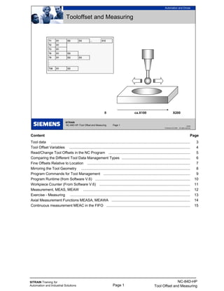
  • 1. SITRAIN Training for Automation and Industrial Solutions Page 1 NC-84D-HP Tool Offset and Measuring SITRAIN NC-84D-HP /Tool Offset and Measuring Page 1 Automation and Drives 1/2008 © Siemens AG 2008 - All rights reserved Tooloffset and Measuring 0 ca.X100 X200 Content Page Tool data .......................................................................................................................................... 3 Tool Offset Variables ........................................................................................................................ 4 Read/Change Tool Offsets in the NC Program ................................................................................. 5 Comparing the Different Tool Data Management Types .................................................................... 6 Fine Offsets Relative to Location ...................................................................................................... 7 Mirroring the Tool Geometry ............................................................................................................ 8 Program Commands for Tool Management ...................................................................................... 9 Program Runtime (from Software V.6) .............................................................................................. 10 Workpiece Counter (From Software V.6) .......................................................................................... 11 Measurement, MEAS, MEAW .......................................................................................................... 12 Exercise - Measuring ....................................................................................................................... 13 Axial Measurement Functions MEASA, MEAWA .............................................................................. 14 Continuous measurement MEAC in the FIFO ................................................................................... 15
  • 2. SITRAIN Training for Automation and Industrial Solutions Page 2 NC-84D-HP Tool Offset and Measuring
  • 3. SITRAIN Training for Automation and Industrial Solutions Page 3 NC-84D-HP Tool Offset and Measuring Structure of the offset memory Every data set can be invoked with a T and D number; in addition to the geometrical data for the tool, it contains other information such as the tool type. Altogether max. 600 data sets per NCU. (From software V.5 max.1500) depending on setting in $MN_MM_NUM_CUTTING_EDGES_IN_TOA and max. 9 data sets per tool. (From software V.5 max.12) depending on setting in MD 18106 Several entries exist for the geometric variables (e.g., length 1 or radius). These are added together to produce a value (e.g. total length 1, total radius) which is then used for the calculations. Exception: In $MC_TOOL_PARAMETER_DEF_MASK geometry value (from software V.5.3) and wear value of the facing axis can be switched to diameter for turning operations. The "reserved" parameters are only taken into account for 3D tool compensation (CUT3DC, CUT3DF) and grinding tools. SITRAIN NC-84D-HP /Tool Offset and Measuring Page 3 Automation and Drives 1/2008 © Siemens AG 2008 - All rights reserved Tool data
  • 4. SITRAIN Training for Automation and Industrial Solutions Page 4 NC-84D-HP Tool Offset and Measuring Data set structure Reserved25 For turningclearance angle24 Applicant (z in G17)Length 112 Ordinate (y in G17)Length 213 Abscissa (x in G17)Length 314 Technology Abscissa (x in G17)Length 323 Ordinate (y in G17)Length 222 Applicant (z in G17)Length 121 For drills not neededRadius15 End radius for CUT3DReserved16 Reserved17 Reserved18 Reserved19 cone angle for CUT3DReserved20 Base/ Holder cone angle for CUT3DReserved11 Reserved10 Reserved9 Wear Reserved8 End radius for CUT3DReserved7 For drills not neededRadius6 Abscissa (x in G17)Length 35 Ordinate (y in G17)Length 24 Applicant (z in G17)Length 13 Geometry: length & radius corrections For turningCutting edge position2 Tool type1 NotesMeaningTool parameter Tool parameter are store in system variables of form $TC_DPn[i,j] $TC_DP1[2,3] T2 D3
  • 5. SITRAIN Training for Automation and Industrial Solutions Page 5 NC-84D-HP Tool Offset and Measuring The modified values only take effect the next time T or D is programmed - even when changed by the operator! From Software V.5 Any changes the operator makes to the tool offset and zero offset in NC STOP are effective and implemented immediately after a new NC START if MD9440=1 Delete Contours: $TC_DP1 [1, 6] =0 Deletes T1 D6 $TC_DP1 [3, 0] =0 Deletes T3 completely $TC_DP1 [0, 0] =0 Deletes complete tool memory The current (selected) offset values can also be read in the system variables: Caution When these system variables are accessed there is no implicit preprocessing stop. With time-critical program sections you therefore need to program STOPRE first. "Flat" Tool Offsets(from software V. 4) In contrast with the standard setting described until now ($MN_MM_TYPE_OF_CUTTING_EDGE=0) it is also possible to assign D numbers that are not connected to the T numbers, e.g. when the tool management is conducted externally. D1 ... D32000 (max. 1500 numbers dep. on memory configuration) Addressing the Parameters: $TC_DP1 [Dn] . .. $TC_DP25 [Dn] Delete "Flat" Tool $TC_DP1 [6] =0 Deletes D6 Offsets $TC_DP1 [0] =0 Deletes complete tool memory SITRAIN NC-84D-HP /Tool Offset and Measuring Page 5 Automation and Drives 1/2008 © Siemens AG 2008 - All rights reserved Read/Change Tool Offsets in the NC Program Programming exercise: N10 R1=$TC_DP3[4,1] reads L1 from T4 D1 N20 $TC_DP12[4,1]= $TC_DP12[4,1]-0.051 changes L1 wear Active tool radius overall$O_TOOLR Active tool length overall m: length 1…3 $P_TOOLL[m] Active correction n: parameter number 1…25 $P_AD[n] Active cutting edge (D- No.)$P_TOOL Active tool number (T- No.)$P_TOOLNO Content of system variablesName
  • 6. SITRAIN Training for Automation and Industrial Solutions Page 6 NC-84D-HP Tool Offset and Measuring Comparing the Possible Tool Data Management Types To software V.3 only "deep" structures: offset call with "T123" From software V.4 in addition "flat direct" structure is possible: offset call with "D32000" From software V.5 in addition "flat indirect" structure is possible: offset call of D123 with "D5" 9 D numbers in PLC DBB... From software V.5 with "deep" structure max. 12 cutting edges per tool, where D number and cutting edge number CE= are separated. You can check the D numbers are uniquely assigned via the CHKDNO command. T3 D1 T123 D1 D2 T4711 D1 T32000 D1 D2 D3 D4 D5 D6 D7 D8 D9 T3 T135 T1358 T1359 T12345678 D2 D33 D100 D120 D121 D122 D123 D124 D125 D32 000 T3 T135 T1358 T1359 T12345678 D2 D33 D100 D120 D121 D122 D123 D124 D125 D32 000 1 100 2 124 3 2 4 33 5 123 6 125 7 66 8 4711 9 122 D5 T3 CE=1 D345 T123 CE=1 D11 CE=2 D1 T4711 CE=1 D471 T32000 CE=1 CE=2 D1 CE=3 D1 CE=4 D2 CE=5 CE=6 CE=7 CE=8 D17 CE=9 D18 CE=1 0
  • 7. SITRAIN Training for Automation and Industrial Solutions Page 7 NC-84D-HP Tool Offset and Measuring For fine offsetting of the tool influence on the machining (e.g. a heavy tool the gantry bends particularly at a specific machining position) location-dependent fine offsets are introduced in software V.5. They are additive to the normal offsets. SITRAIN NC-84D-HP /Tool Offset and Measuring Page 7 Automation and Drives 1/2008 © Siemens AG 2008 - All rights reserved Fine Offsets Relative to Location DL1 ... 6 (per D No. max. 6 dep. on MD18108) with D selection, DL1 is automatically active Per DL offset 2 values: Wear value $TC_SCPxy[t,d] Setup value $TC_ECPxy[t,d] DL No. 1 ... 6 Parameter No. 1 ... 24 state = DELDL[t,d] Deletes all additive offsets for the cutting edge of the tool state = DELDL[t] Deletes all additive offsets for all cutting edges of the tool state = DELDL Deletes all additive offsets for all cutting edges of all tools successful if state =0
  • 8. SITRAIN Training for Automation and Industrial Solutions Page 8 NC-84D-HP Tool Offset and Measuring Up until software V.4 it was necessary to create a new data set (new D No.) to generate a mirrored tool length. Example for reading and changing tool offsets Task A new data set D2 is to be created and selected for a rotatable tool (machining "from below") with negative tool length L1 in a subroutine for the active tool. Sample Solution NEGL1_SPF STOPRE $TC_DP1[$P_TOOLNO,2]= $TC_DP1[$P_TOOLNO,1] $TC_DP3[$P_TOOLNO,2]= $P_TOOLL[1] $TC_DP4[$P_TOOLNO,2]= $P_TOOLL[2] $TC_DP5[$P_TOOLNO,2]= $P_TOOLL[3] $TC_DP6[$P_TOOLNO,2]= $TC_DP6[$P_TOOLNO,1] D2 M17 From Software V. 5 Mirroring of the tool lengths and base values automatically becomes effective with $SC_MIRROR_TOOL_LENGTH=1 when the appropriate geometry axis is mirrored. $SC_MIRROR_TOOL_WEAR=1 activates the mirroring for the wear data incl. the DL values. SITRAIN NC-84D-HP /Tool Offset and Measuring Page 8 Automation and Drives 1/2008 © Siemens AG 2008 - All rights reserved Mirroring the Tool Geometry SD42900 $SC_MIRROR_TOOL_LENGTH =1 Mirrors tool lengths and tool base dimensions SD42910 $SC_MIRROR_TOOL_WEAR =1 Mirrors tool length wear values incl. DL Mirroring is effective when the associated axis is mirrored SD42920 $SC_WEAR_SIGN_CUTPOS Wear +/- signs dep. on cutting edge position SD42930 $SC_WEAR_SIGN =1 Inverts the sign for all wear dimensions SD42940 $SC_TOOL_LENGTH_CONST =0 Assignment of tool lengths dep. on G17 ... 17 ... 19 indep. of G17 ... G19 in these planes -17 ...-19 the same but with swapped axes of the respective machining plane Cutting edge L1 mirr. L2 mirr. position 1 2 invert 3 invert invert 4 invert 5 6 7 invert 8 invert 9
  • 9. SITRAIN Training for Automation and Industrial Solutions Page 9 NC-84D-HP Tool Offset and Measuring ...= NEWT (...) Create new tool The function returns the automatically generated internal T number as return parameter. If no duplo number is specified, this is generated automatically by the tool management. Example: DEF INT T_NO, DUPLO_NO = 7 T_NO=NEWT("DRILL", DUPLO_NO) DELT(...) Delete tool The DELT function can be used to delete a tool without referring to the T number. Example: DELT("MYTOOL",DUPLO_NR) ...=GETT(...) Read T No. The GETT function returns the T number required to set the tool data for a tool. If there are several tools with the specified identifier, the T number of the first possible tool of these tools is returned. - 1: No tool found. Example: R10=GETT("DRILL", DUPLO_NO) $TC_DP1[GETT("DRILL, DUPLO_NO),1]=100 SETPIECE(...) Preset workpiece counter number of units is decremented by the specified number as set in $A_MONIFACT. (Spindle spec. optional) (Timer or count) = 10 1 min. machining = 10 min. operating life = 0 No wear Example: SETPIECE(1) Workpiece counter of main spindle is decr. by 1 SETPIECE(4,2)Workpiece counter of 2nd spindle is decr. by 4 Control of wear time as set in MD20310 bit 17 = 0 Timer is running if G0 is not used for traversing = 1 Timer ON/OFF via PLC (DB x 1.3) GETSELT(...) Read the selected T No. For accessing the compensation data for the next tool already before M6. Example:GETSELT (R1) Get No. of the (pre)activated tool of main spindle GETSELT (R2,2) No. of the (pre)activated tool of 2nd spindle SITRAIN NC-84D-HP /Tool Offset and Measuring Page 9 Automation and Drives 1/2008 © Siemens AG 2008 - All rights reserved Program Commands for Tool Management Find out preselected tool No. (t- No.)GETSELT(x) Decrement number of pieces (for how many, spindel- No.) SETPIECE (x,y) Find out T- Number… GETT (“WZ“,DUPLO_NR) delete tool, duplo number optionalDELT (“WZ“,DUPLO_NR) Create new tool, duplo number optional… =NEWT (“WZ“,DUPLO_NR) Used symbols spindel- No.x Find out T- Number… GETT (“WZ“,DUPLO_NR) Tool parter No.DUPLO_NR Tool name“WZ“
  • 10. SITRAIN Training for Automation and Industrial Solutions Page 10 NC-84D-HP Tool Offset and Measuring Information on the program runtime and the part count is provided to assist the machine tool operator. The functions defined for this purpose are not identical to the functions of tool management and are intended primarily for systems without tool management. The desired information must be specified in defined machine data and can be manipulated via system variables in the NC and/or PLC program. The information is available to the MMC via the operator panel/PLC interface. A dedicated display screen for the SINUMERIK 802D control is provided for program runtime and workpiece counter. Exercise Program a circle with diameter= 75 mm and traverse it with F350. How many minutes does the machining take? (theoretically π × 75 / 350 = 0.673 min) R1= $AN_POWERON_TIME G3 G91 I= 75/2 F350 MSG ("Runtime= "<< R1- $AN_POWERON_TIME) M30 SITRAIN NC-84D-HP /Tool Offset and Measuring Page 10 Automation and Drives 1/2008 © Siemens AG 2008 - All rights reserved Program Runtime (from Software V.6) $AN_SETUP_TIME Time since last INITIAL.INI or series start-up [min] $AN_POWERON_TIME Time since last Power ON or last POR [min] $AC_OPERATING_TIME Sum of machining times since Power ON [s] $AC_CYCLE_TIME Runtime of active program until now [s] $AC_CUTTING_TIME Tool cutting time (machining feed) since PO [s] MD 27860 $MC_PROCESSTIMER_MODE Bit 0=1 $AC_OPERATING_TIME active Bit 1=1 $AC_CYCLE_TIME active Bit 2=1 $AC_CUTTING_TIME active Bit 4=1 Measurement also with DRY Bit 5=1 Measurement also with PRT
  • 11. SITRAIN Training for Automation and Industrial Solutions Page 11 NC-84D-HP Tool Offset and Measuring Another machine data is required for configuration of the workpiece counter: MD 27880 $MC_PART_COUNTER Bit 0=1 $AC_REQUIRED_PARTS is monitored Bit 1=0 Alarm/VDI output if equal to $AC_ACTUAL_PARTS Bit 1=1 Alarm/VDI output if equal to $AC_SPECIAL_PARTS Bit 4=1 Counter $AC_TOTAL_PARTS active Bit 5=0 Counter $AC_TOTAL_PARTS is incremented with M2/M30 Bit 5=1 Counter $AC_TOTAL_PARTS incremented at M command specified in MD 27882 $MC_PART_COUNTER_MODE[0] Bit 8=1 Counter $AC_ACTUAL_PARTS active Bit 9=0 Counter $AC_ACTUAL_PARTS is incremented with M2/M30 Bit 9=1 Counter $AC_ACTUAL_PARTS incremented at M command specified in MD 27882 $MC_PART_COUNTER_MODE[1] Bit 12=1 Counter $AC_SPECIAL_PARTS active Bit 13=0 Counter $AC_SPECIAL_PARTS is incremented with M2/M30 Bit 13=1 Counter $AC_SPECIAL_PARTS incremented at M command specified in MD 27882 $MC_PART_COUNTER_MODE[2] All workpiece counters are declared as inactive in the default machine data set. The counters are activated by default for the SINUMERIK 802D. SITRAIN NC-84D-HP /Tool Offset and Measuring Page 11 Automation and Drives 1/2008 © Siemens AG 2008 - All rights reserved Workpiece Counter (From Software V.6) $AC_REQUIRED_PARTS Setpoint count (alarm output and $AC_ACTUAL_PARTS=0) $AC_TOTAL_PARTS Part count since Power ON $AC_ACTUAL_PARTS Part count since last reset $AC_SPECIAL_PARTS Part count since last reset (user-defined) like $AC_ACTUAL_PARTS, but without automatic reset MD 27882 $MC_PART_COUNTER_MCODE[0...2] M function which triggers the counting process: [0] for $AC_TOTAL_PARTS [1] for $AC_ACTUAL_PARTS [2] for $AC_SPECIAL_PARTS
  • 12. SITRAIN Training for Automation and Industrial Solutions Page 12 NC-84D-HP Tool Offset and Measuring MEAS MEAW The measurement (with or without delete distance-to-go) is performed in a path motion (e.g. with G1). The positions are captured for all geometry axes at the switching edge of the measuring probe and written to: $AA_MM[axis] in machine coordinate system $AA_MW[axis] in workpiece coordinate system When this variable is read, from software V.4.3 an implicit preprocessing stop is generated. With earlier versions it was necessary to program a preprocessing stop with STOPRE. Measuring Success You can query the measuring success until the next measurement command by means of the status variable $AC_MEA[n] (n= number of the measuring probe): 1= Measurement successful 0= Probe not deflected Switching status The current output state of the probe is written in $A_PROBE[n] Stopping Path The stopping path after delete distance-to-go corresponds to the following error plus deceleration distance. Feedforward control FFWON is absolutely necessary! Following error at KV=1(MD 32200) and F1000 = 1mm Deceleration distance at a=10m/s2 (MD 32300) s=v2/2a = ca. 0.015mm Determine stopping path experimentally: $AA_MM[axis]–$AA_IM[axis] CAUTION: Measuring probes often have a delay that can be activated! GEOAX The measurement does not work with simulated geometry axes as often found as Z axis on our training units. Deactivate: N1 GEOAX ( ) N2 GEOAX (0, Z1) ... N99 GEOAX ( ) Here Z1 is the channel axis name. When using GEOAX it must not be identical with the geometry axis name (change alarm 14414 MD20080). SITRAIN NC-84D-HP /Tool Offset and Measuring Page 12 Automation and Drives 1/2008 © Siemens AG 2008 - All rights reserved Measurement, MEAS, MEAW N10 FFWON N20 MEAS=+1 G1 F1000 X100 N30 STOPRE N40 R1= $AA_MM [X] Measurement with delete distance-to-go at deflection of measuring probe at 1st measuring input Measurement with delete distance-to-go at deflection of measuring probe at 1st measuring input Polarity of measuring probe used: MD13200 MEAS_PROBE_LOW_ACTIVE[n]
  • 13. SITRAIN Training for Automation and Industrial Solutions Page 13 NC-84D-HP Tool Offset and Measuring Programming Exercise - Measuring Determine the center point of a hole/slot (carry out two measurements in X direction and form the mean value) and make this position available in R0 rounded to three decimal places. Solution: N1 GEOAX ( ) N2 GEOAX ( 0, Z1 ) N3 G0 G90 X100 N4 MEAS=1 G1 X0 . .. N5 . . . . . . . . . . . . . . . . . . . . . . . . . . . . . . . . . . . . . . . . . . . . . . . . . . . N6 . . . . . . . . . . . . . . . . . . . . . . . . . . . . . . . . . . . . . . . . . . . . . . . . . . . N7 . . . . . . . . . . . . . . . . . . . . . . . . . . . . . . . . . . . . . . . . . . . . . . . . . . . N8 . . . . . . . . . . . . . . . . . . . . . . . . . . . . . . . . . . . . . . . . . . . . . . . . . . . N9 . . . . . . . . . . . . . . . . . . . . . . . . . . . . . . . . . . . . . . . . . . . . . . . . . . . N10 . . . . . . . . . . . . . . . . . . . . . . . . . . . . . . . . . . . . . . . . . . . . . . . . . . N11 . . . . . . . . . . . . . . . . . . . . . . . . . . . . . . . . . . . . . . . . . . . . . . . . . . N12 . . . . . . . . . . . . . . . . . . . . . . . . . . . . . . . . . . . . . . . . . . . . . . . . . . SITRAIN NC-84D-HP /Tool Offset and Measuring Page 13 Automation and Drives 1/2008 © Siemens AG 2008 - All rights reserved Exercise - Measuring 0 approx. X100 X200
  • 14. SITRAIN Training for Automation and Industrial Solutions Page 14 NC-84D-HP Tool Offset and Measuring With MEASA, MEAWA per movement up to 4 measurements are possible; with MEASA delete distance-to-go is performed after the last trigger pulse. The measurement results are found in $AA_MM1...4[axis] for event 1...4 in the MCS $AA_MW1...4[axis] for event 1...4 in the WCS Example MEAWA Two light barriers are to monitor direction and speed of the workpiece flow on a remote controlled axis in the following expected form: MEAWA [U]= (02,1,2,-1,-2) STOPRE R1=$AA_MM1[U] R2=$AA_MM2[U] R3=$AA_MM3[U] R4=$AA_MM4[U] SITRAIN NC-84D-HP /Tool Offset and Measuring Page 14 Automation and Drives 1/2008 © Siemens AG 2008 - All rights reserved Axial Measurement Functions MEASA, MEAWA Measuring with delete distance-to- go within up to 4 trigger pulses Measuring without delete distance-to-go within up to 4 trigger pulses Mode is using a two digit number: left.: used encodernumber right: measuring procedure Active encoder 0 encoder 1 1 encoder 2 2 both encoders 3 Terminate measuring 0 mesure in order of trigger pulses 1 Measure in order of programmed sequence 2 MEAWA[ax]= [mode, ±n, ±n, ±n, ±n) G1 X… MEASA[ax]= [mode, ±n, ±n, ±n, ±n) G1 X…
  • 15. SITRAIN Training for Automation and Industrial Solutions Page 15 NC-84D-HP Tool Offset and Measuring MEAC (from Software V.4) Allows continuous measurement of data sequences in up to 10 FIFO buffers $AC_FIFO1[n] ... $AC_FIFO10[n] (number in $MC_NUM_AC_FIFO). The measured values are available as machine coordinates. The max. FIFO length is defined in $MC_LEN_AC_FIFO. If the FIFO is full, measurement is automatically terminated. The FIFO can only be read out once, it is then empty. Endless measurement is possible by cyclically reading out the FIFO. Mode 0 Cancel measuring job 1 to max. 4 trigger events that can be activated simultaneously 2 to max. 4 trigger events that can be activated in succession 3 to max. 4 trigger events that can be activated in succession , but no monitoring of trigger event 1 at START Example At axis motion of the X axis a measurement sequence is to be created in FIFO1 and stored in an array VALUE. The falling edge of probe 1 is evaluated. DEF REAL VALUE [100] $AC_FIFO1[4]=0 ;Delete FIFO G0 X0 MEAC[X]= (1,1,-1) G1 X100 F300 MEAC[X]= (0) ;Cancel measurement WHILE $AC_FIFO1[4] <>0 VALUE[$AC_FIFO1[4]-1]= $AC_FIFO1[0] ;Relocate measured values ENDWHILE M0 STOPRE M30 SITRAIN NC-84D-HP /Tool Offset and Measuring Page 15 Automation and Drives 1/2008 © Siemens AG 2008 - All rights reserved Continuous measurement MEAC in the FIFO Continuously measuring into FIFO (without delete dist.-to-go) MEAC[ax]= [mode, FIFO_No, ±n, ±n, ±n, ±n) G1 X… The measurement results are in the FIFO. At access the index specifies the function: The FIFO is deleted by resetting the number of elements: e.g.: $AC_FIFO2[4]=0 Optional Act. write indexn = 5 Number of valuesn = 4 Summary of values (read only)n = 3 Read/ overwrite last valuen = 2 R/W value 1…N= 6 Read/ overwrite oldest valuen = 1 Writing a new value or read and delete oldest value n = 0