
Recommended
More Related Content
What's hot
What's hot (20)
Similar to Power System Operations Guide
Similar to Power System Operations Guide (20)
Recently uploaded
Recently uploaded (20)
Power System Operations Guide
- 1. SECTION 16 POWER-SYSTEM OPERATIONS Gustavo Brunello Applications Consultant, General Electric Company Christa Lorber Motorola, Inc. Hesham Shaalan Associate Professor of Electrical Engineering, U. S. Merchant Marine Academy Douglas M. Staszesky Marketing Director, S&C Electric Company George R. Stoll President, Utility Telecom Consulting Group, Inc. CONTENTS 16.1 THE ENERGY MANAGEMENT SYSTEM . . . . . . . . . . . . .16-2 16.1.1 Introduction . . . . . . . . . . . . . . . . . . . . . . . . . . . . . .16-2 16.1.2 Overview of Energy Management System Functions . . . . . . . . . . . . . . . . . . . . . . . . . . . . . . . .16-3 16.2 RELAYING AND PROTECTION . . . . . . . . . . . . . . . . . . . .16-14 16.3 POWER-SYSTEM COMMUNICATIONS . . . . . . . . . . . . . .16-26 16.3.1 Introduction . . . . . . . . . . . . . . . . . . . . . . . . . . . . .16-26 16.3.2 Communications/Control Hierarchy . . . . . . . . . . .16-26 16.3.3 Utility Communications Network Design Considerations . . . . . . . . . . . . . . . . . . . . . . . . . . .16-26 16.3.4 Specialized Power System Communications . . . . .16-28 16.3.5 Protective Relay Communication Channel Requirements . . . . . . . . . . . . . . . . . . . . . . . . . . . .16-28 16.3.6 Telemetering and Telecontrol . . . . . . . . . . . . . . . .16-29 16.3.7 Automatic Generation Control . . . . . . . . . . . . . . .16-30 16.3.8 Voice Communications . . . . . . . . . . . . . . . . . . . . .16-30 16.3.9 Other Data Communication Links . . . . . . . . . . . . .16-31 16.3.10 Communication Alternatives . . . . . . . . . . . . . . . .16-31 16.3.11 Communications Media/Service Type . . . . . . . . . .16-32 16.3.12 Private Point-to-Point Microwave Systems . . . . . .16-33 16.3.13 Leased Telephone Circuits . . . . . . . . . . . . . . . . . .16-34 16.3.14 Satellite Services . . . . . . . . . . . . . . . . . . . . . . . . .16-34 16.3.15 Private and Commercial Land Mobile Radio Systems . . . . . . . . . . . . . . . . . . . . . . . . . . . . . . . .16-35 16.3.16 Cellular and PCS Wireless Services . . . . . . . . . . .16-35 16.3.17 VHF and UHF Radio Data Links . . . . . . . . . . . . .16-36 16.3.18 Power-Line Carrier . . . . . . . . . . . . . . . . . . . . . . . .16-36 16.3.19 Privately Owned Fiber Optic Cable Systems . . . . .16-36 REFERENCES . . . . . . . . . . . . . . . . . . . . . . . . . . . . . . . . . . . . . . . .16-38 16.4 INTELLIGENT DISTRIBUTION AUTOMATION . . . . . . .16-38 16.4.1 Automated Feeder Switching Systems . . . . . . . . .16-39 16.4.2 Summary . . . . . . . . . . . . . . . . . . . . . . . . . . . . . . .16-45 16-1 Beaty_Sec16.qxd 17/7/06 8:50 PM Page 16-1 Downloaded from Digital Engineering Library @ McGraw-Hill (www.digitalengineeringlibrary.com) Copyright © 2006 The McGraw-Hill Companies. All rights reserved. Any use is subject to the Terms of Use as given at the website. Source: STANDARD HANDBOOK FOR ELECTRICAL ENGINEERS
- 2. 16-2 SECTION SIXTEEN 16.5 IMPACTS OF EFFECTIVE DSM PROGRAMS . . . . . . . . .16-45 16.5.1 Introduction . . . . . . . . . . . . . . . . . . . . . . . . . . . . .16-45 16.5.2 Commercial-Sector DSM . . . . . . . . . . . . . . . . . . .16-45 16.5.3 Effective DSM Programs and Their Impacts . . . . .16-46 16.5.4 Projected Total DSM Program Impacts . . . . . . . . .16-48 16.5.5 Conclusion . . . . . . . . . . . . . . . . . . . . . . . . . . . . . .16-48 APPENDIX . . . . . . . . . . . . . . . . . . . . . . . . . . . . . . . . . . . . . . . . . .16-49 REFERENCES . . . . . . . . . . . . . . . . . . . . . . . . . . . . . . . . . . . . . . . .16-50 16.1 THE ENERGY MANAGEMENT SYSTEM 16.1.1 Introduction The management of the real-time operation of an electric power network is a complex task requir- ing the interaction of human operators, computer systems, communications networks, and real-time data-gathering devices in power plants and substations. There are several concerns that operations departments must take into account in the operation of an electric power system. First and most important is the safety of its personnel and the public. This requires that steps in switching the net- work be made in accordance with safety procedures so that the lives of utility personnel in the affected substations are not endangered. Next, operating departments are concerned with the secu- rity or reliability of the supply of electric energy to customers. In most modern societies, the con- tinuous supply of electric energy is extremely important, and any interruption of a large number of customers at one time is considered an emergency. Finally, the operations department is charged with operating the power system as economically as possible within safety and security limits. This section deals with the systems that are used to manage a modern utility network. Such a sys- tem is usually called an energy management system (EMS) and consists of computers, display devices, software, communications channels, and remote terminal units that are connected to control actuators and transducers in substations and power plants. Broadly speaking, these systems are bro- ken down into the following tasks: Generation control and scheduling Network analysis Operator training The task of managing the generation of a large power system starts with the control of generation to maintain system frequency and tie-line flows while keeping the generators at their economic output. To this are added the economic dispatch, which determines the most economic output of each genera- tor for a given load, the on/off scheduling or commitment of generators to meet varying load demands, and the determination of the pricing and amount of energy to buy and sell with neighboring utilities. The task of managing the transmission system network requires the monitoring of thousands of telemetered values, the estimation of the electrical state of the network given the telemetered values, and the estimation of the effect of any plausible outage on the operation of the network. The security- analysis problem requires that the EMS be capable of analyzing hundreds or thousands of possible outage events and informing the operator of the best strategy to handle these outages if they result in an overload or voltage limit violation. The operators must be highly trained in the use of the EMS and how to respond to emergencies. To be sure that operators are trained effectively, most utilities incorporate a simulator into their EMS that is capable of simulating the effects of an emergency on the power system. The operator is then required to “respond” by taking actions on the simulator that corrects the emergency problem. In this way new operators can be introduced to emergency procedures and experienced operators can have their training refreshed. Beaty_Sec16.qxd 17/7/06 8:50 PM Page 16-2 Downloaded from Digital Engineering Library @ McGraw-Hill (www.digitalengineeringlibrary.com) Copyright © 2006 The McGraw-Hill Companies. All rights reserved. Any use is subject to the Terms of Use as given at the website. POWER-SYSTEM OPERATIONS
- 3. The EMS systems now in use in a modern power-system operations department are very large computer systems that require a large maintenance staff. The EMS is usually one of the largest com- puter systems in use in a utility company and often has within its database the needed information for many of the other engineering and design departments. In recent years, the concept of open sys- tems has taken hold within utility EMS systems so that they are approaching a truly distributed form of command and control system. 16.1.2 Overview of Energy Management System Functions Supervisory Control and Data Acquisition (SCADA) Subsystem. Supervisory control supports operator control of remote (or local) equipment, such as opening or closing a breaker, with security features, such as authorization and a select-verify-execute procedure. The data-acquisition subsys- tem gathers telemetered data for use by all other functions within the EMS. Data are obtained from various sources including remote terminal units (RTUs) installed in plants and substations and devices near to the system control center by local input-output (I/O) equipment. A SCADA system provides three critical functions in the operation of an electric utility network: Data acquisition Supervisory control Alarm display and control Data-Acquisition Function. The data-acquisition subsystem periodically collects data in processed or raw form from remote terminal units. Data acquisition consists of five functional areas: Data collection Data processing Data monitoring Special calculations Scan configuration control Data collection is responsible for periodically acquiring data from remote terminal units at the appropriate rate. In addition, data collection monitors the various scans to make sure they initiate and complete within the current time period. Data processing is responsible for converting analog values from raw data to engineering units. It is also responsible for converting digital status points to a system convention of device states (0 for closed and 1 for open). Data for points that are manually replaced in the database are not usu- ally processed. Data processing is also responsible for handling data obtained from data links to other computer systems. Data monitoring interfaces with the alarm processor and notifies it when the following occur: Devices change state Values exceed operating limits Data monitoring also provides deadband and return-to-normal features. Special calculations support various standard calculations such as Copy a value MVA from MW and Mvar measurements MVA from kV and amperes Amperes from MVA and kV measurements Other common periodic calculations Calculated values are derived periodically from scanned data in the database. POWER-SYSTEM OPERATIONS 16-3 Beaty_Sec16.qxd 17/7/06 8:50 PM Page 16-3 Downloaded from Digital Engineering Library @ McGraw-Hill (www.digitalengineeringlibrary.com) Copyright © 2006 The McGraw-Hill Companies. All rights reserved. Any use is subject to the Terms of Use as given at the website. POWER-SYSTEM OPERATIONS
- 4. Scan configuration control removes a terminal unit from the scan or switches the channel assign- ment when sustained communications errors occur. Scan configuration control periodically attempts to reestablish communications with terminals, which have been removed from the scan. Supervisory Control Function. This function allows the operator to control remote devices and to condition or replace values in the database. All operations are multistep procedures. Selection of the device to be operated is the first step. Next is the visual verification step, and the final step is oper- ator execution or cancellation. Data conditioning includes operations such as the following: Manual replacement of telemetered data Alarm inhibit/enable Reverse normal (change definition of the normal state of a device) Bypass enter (of failed telemetry) Tag/tag clear Summary displays support the manual replace, alarm inhibit/enable, and tag/tag clear functions. Entries on these summaries are typically in inverse chronological order, the most recent entry being at the top of the summary. Alarm Display and Control Function. The subsystem is responsible for the presentation of alarms to the operator. It supports alarm presentation and alarm presentation control. Alarm presentation is responsible for constructing the alarm message, organizing alarms in categories, maintaining an alarm summary display and abnormal summary, maintaining console logs, initiating audio/visual annunciators, and interfacing to other functions (e.g., the mapboard). Presentation control assigns priorities to alarm messages, recognizes points which are inhibited from alarming or manually replaced by the operator, and provides operator functions such as alarm acknowledgment. User Interface Subsystem. The most visible feature of an energy management system is the user interface (UI) subsystem, which includes the following: Presentation of system data on visual displays Entry of data into the EMS through a keyboard Validation of data entry Support of supervisory control procedures Output of displays to a printer or video copier Operator execution control of application programs Displays are created by using an interactive display builder, which allows definition of linkages between areas on the display and the EMS database for retrieval and entry of data. Also, the user can define function keys or function keys/display locations (poke points) when building a display to cause the presentation of another display or to initiate the execution of an application program. The display builder allows the operator to create or modify the static elements of the display and add, modify, or delete the data and control linkages of the display. When the operator is satisfied with the display, the display definition is saved in the display file for later use by UI. Displays are presented on a cathode ray tube (CRT) display at a console. An EMS console con- sists of one or more CRTs having full graphics capability, a display controller, a keyboard, and a trackball or mouse. The flexibility in display format provided to the user allows a single subsystem to support a wide range of display types. These typically include Menu or index displays One-line schematic circuit diagrams 16-4 SECTION SIXTEEN Beaty_Sec16.qxd 17/7/06 8:50 PM Page 16-4 Downloaded from Digital Engineering Library @ McGraw-Hill (www.digitalengineeringlibrary.com) Copyright © 2006 The McGraw-Hill Companies. All rights reserved. Any use is subject to the Terms of Use as given at the website. POWER-SYSTEM OPERATIONS
- 5. System overviews Substation and generation displays Transmission line displays Summary displays System configuration displays Application program displays Trend or plot displays Disturbance data collection displays Historical data storage displays Report displays Other displays Communications Subsystem. The communications subsystem encompasses management of a local-area network supporting the EMS itself, such as a dual-redundant Ethernet, token ring, or fiberoptic communications medium, and support of communication with other computing systems and field equipment. In addition to the users within the control room, there may be schedulers, trainees, programmers, engineers, and executives who require access to the EMS through standard console displays, remote displays, or even personal computers. All these have to be connected to the EMS via a local area net- work that may extend outside the control center building to other facilities. Other connections within the utility may include off-line engineering systems for planning or long-range scheduling, other control systems, for example, load management, distribution, or plant management, and control and corporate (billing and customer) computer systems. External commu- nications are typically with other utilities or power pools. Information Management Subsystem. The information management subsystem supports definition of and access to data used by the EMS. This includes all the static data descriptive of the power sys- tem, the EMS configuration, and data shared with other systems. It also includes organization of data for specific uses, for example, for data acquisition and monitoring and for network analysis algorithms. In current EMS configurations, the database is distributed. This results in a need to facilitate data access without burdening either the operator or the applications programmers and other system users. Evolution of software standards and tools in the computer industry has led to products that support these needs, such as relational database managers and computer network file and resource managers. Applications Subsystem. The applications extend the usefulness of an EMS, allowing data gath- ered by the SCADA system to be used to optimize and control the power system. An EMS overview is shown in Fig. 16-1. Generation Control Applications. An interconnected system is made up of one or more control areas, each of which is defined as that portion of an interconnected system to which a common gen- eration control scheme is applied. It also may be regarded as that portion of the interconnected sys- tem which is expected to regulate its own generation to follow its own load changes. It may consist of a single utility, or a part of one, or a whole group of pooled utilities. In each case, a control area would include all the generating units, loads, and lines that fall within its prescribed boundaries. All the control areas of an interconnection, taken together, should account for all the generation, load, and ties of the interconnected system. A single-area system is one in which the entire interconnected system is encompassed within one control area. One control system provides the basic regulation for the entire interconnection and does not distinguish between the locations of load changes within the interconnection. A multiple-area system is one in which there are many control areas, each with its own control system, each normally POWER-SYSTEM OPERATIONS 16-5 Beaty_Sec16.qxd 17/7/06 8:50 PM Page 16-5 Downloaded from Digital Engineering Library @ McGraw-Hill (www.digitalengineeringlibrary.com) Copyright © 2006 The McGraw-Hill Companies. All rights reserved. Any use is subject to the Terms of Use as given at the website. POWER-SYSTEM OPERATIONS
- 6. adjusting its own generation in response to load changes within its own area. All the interconnected systems in the United States and Canada operate on a multiple-area basis. Speed Governor. The generating unit’s speed governor, along with governor-controlled steam valves (in a thermal plant) and a speed changer which provides for adjustment of the governor set point, con- stitutes the primary control loop for maintaining frequency at the unit level. The steady-state speed reg- ulation characteristic of the speed governor relates a per-unit change in rated speed (y axis) to a per-unit change in rated load (x axis) and is a straight line with negative slope (called droop). Thus, with the speed changer set to provide rated speed for a given load, changing the set point shifts the straight- line characteristic along the x axis so that more or less output is demanded for constant rated speed. The automatic generation control (AGC) signal to raise/lower the set point (or signal for a directed set point) closes the system-level control loop and is also referred to as supplementary control. Operating Objectives of Generation and Power-Flow Control. Automatic control of generation and power flow is an essential need for the smooth, neighborly, and effective operation of a wide- spread interconnected system. On a multiple-area interconnection, the regulating or control objec- tives are threefold: Objective 1. Total generation of the interconnection as a whole must be matched, moment to moment, to the total prevailing customer demand. This in itself is achieved by the self-regulating forces of the system. 16-6 SECTION SIXTEEN FIGURE 16-1 Energy management system. Beaty_Sec16.qxd 17/7/06 8:50 PM Page 16-6 Downloaded from Digital Engineering Library @ McGraw-Hill (www.digitalengineeringlibrary.com) Copyright © 2006 The McGraw-Hill Companies. All rights reserved. Any use is subject to the Terms of Use as given at the website. POWER-SYSTEM OPERATIONS
- 7. Objective 2. Total generation of the interconnected system is to be allocated among the partici- pating control areas so that each area follows its own load changes and maintains scheduled power flows over its interties with neighboring areas. This objective is achieved by area regulation. Objective 3. Within each control area, its share of total system generation is to be allocated among available area generating sources for optimum area economy, consistent with area security and environmental considerations. This objective is achieved by economic dispatch, supplemented as required by security and environmental dispatch. The means of achieving objectives 2 and 3 are referred to as supplementary control, or currently— and more generally—as AGC. Such control may be regarded as a reallocation control redistributing the systemwide governing responses to load changes in various areas to generators within the areas that had the change. Each area then follows its own load change, with scheduled internal distribu- tion. On a single-area system, objective 2 does not apply. These functions act at the overall system level to regulate the real power output of generation, economically allocate demand among committed units, calculate various reserve quantities, deter- mine production costs, and account for interchange of power between utilities and/or control areas. Automatic Generation Control. Automatic generation control, sometimes called load-frequency con- trol (LFC), regulates power system in terms of maintaining scheduled system frequency and scheduled net interchange. Automatic generation control is implemented as a closed-loop feedback controller. The error signal is determined either as a computed area control error (ACE) for a control area or a given area requirement (AR) in some power pool control structures. Positive ACE indicates overgeneration; posi- tive AR indicates undergeneration. The ACE calculation is based on frequency deviation from schedule, net interchange deviation, or a composite tie-line bias. In tie-line bias control mode, interconnected con- trol areas jointly participate in maintaining frequency, which is uniform among areas, but are individu- ally responsible for maintaining each area’s scheduled net interchange. The formula for this is where the summation is over all tie-line megawatts (TMW), I is the current scheduled net inter- change level, and B is tie-line bias, which converts frequency deviation to real power, usually expressed as MW/tenth Hz. B is characteristic of the installed capacity (MW) of the control area and is usually a constant. Additional terms or modifications to the formula are used to account for cor- rection of time errors, inadvertent interchange payback, and so on. Area control error is a noisy signal and so requires processing. Processing also includes provi- sion for proportional, integral, and anticipatory (or derivative) control characteristics for AGC as a feedback controller. Integral control is necessary to prevent long-term offset in frequency and to ensure that ACE crosses zero (the normal set point) frequently. System control requirements thus determined from processed ACE are allocated to generating units based on several criteria. Unit Control Considerations. Key considerations are The deviation in each unit’s loading from the most recent economic assignment—MW level The deviation of total system load since the last economic dispatch The current value of ACE Economic base points are assigned by the economic dispatch (ED) function, and LFC will drive unit loading toward these assignments unless there are overriding conditions. This mode is termed mandatory unit control (mandatory with respect to economics). An overriding condition may be that ACE exceeds a threshold beyond which correcting ACE takes precedence. In this case, AGC is operating in a permissive mode (with respect to economics). Here units are inhibited from moving against correction of ACE. If ACE exceeds a larger threshold, an emergency assist mode is entered. Here all units move to correct ACE and may move against their economic directions, that is, away from economically assigned base points. ACE B( factual fscheduled) (gTMW Ischeduled) POWER-SYSTEM OPERATIONS 16-7 Beaty_Sec16.qxd 17/7/06 8:50 PM Page 16-7 Downloaded from Digital Engineering Library @ McGraw-Hill (www.digitalengineeringlibrary.com) Copyright © 2006 The McGraw-Hill Companies. All rights reserved. Any use is subject to the Terms of Use as given at the website. POWER-SYSTEM OPERATIONS
- 8. Units participate in ACE reduction in proportion to regulating participation factors, which may be operator-entered or calculated from various criteria according to individual company or pool operating policies. Units participate in adjusting to the deviation in system load since the last ED by use of economic participation factors, produced by ED. In some systems, a single set of participation factors is used. Unit desired generation is calculated according to the preceding rules, and control output is sent to generating station RTUs either as MW set points or raise/lower signals as appropriate to the local generating unit plant-control equipment. Control of each unit assigned to automatic regulation is performed by a separate unit-control loop (feedback controller). Here the set point is unit desired generation already obtained. Models of indi- vidual unit dynamic response to previously issued control commands are compared with actual telemetered output of the unit in determining the degree of new control to be issued. AGC Operator/Dispatcher User Interface. Typical AGC displays used by system operators include System summary—provides an overview of system control information such as area control error, reserve quantities, incremental costs, lambda (from ED), and AGC control mode states and allows the operator to change these states or enter key parameters. Generation summary—summarizes current status and output of all generating units and may pro- vide for operator changes to unit status. Station/plant summary—shows detail related to operation of individual units, limits, fuels, costs, and so on. Tie-line summary—shows telemetered real and reactive power flow on all tie lines and net total real power interchange and may show line limits. Figure 16-2 shows an overview of a typical AGC program. 16-8 SECTION SIXTEEN FIGURE 16-2 Overview of an automatic generation control system. Beaty_Sec16.qxd 17/7/06 8:50 PM Page 16-8 Downloaded from Digital Engineering Library @ McGraw-Hill (www.digitalengineeringlibrary.com) Copyright © 2006 The McGraw-Hill Companies. All rights reserved. Any use is subject to the Terms of Use as given at the website. POWER-SYSTEM OPERATIONS
- 9. Interchange Scheduling. The interchange transaction scheduler (ITS) function supports the oper- ator in entering (defining), editing, and reviewing power interchange schedules with neighboring control areas/utilities. The schedules are usually negotiated by the operator over the telephone with other operators in control rooms at other utilities. These schedules are utilized principally by AGC and energy accounting. Schedules are established by utility and by account within each utility. Examples of accounts include firm or nonfirm energy and capacity purchases, sales, and so on. Schedules may be defined on a daily hour-by-hour basis or on a start/stop date and time basis according to company or pool operating procedures. Various entry displays support definition of such schedules. Other displays are used to summarize transactions by company, account, or chronology. Given a multitude of concurrently active transactions, a net profile of interchange is constructed in order to provide AGC with the instantaneous net scheduled interchange needed for real-time sys- tem regulation. At the end of each hour, scheduled transactions are compared with actual data in the energy accounting function to maintain historical records. An emergency scheduling capability allows the operator to enter a single net schedule of inter- change to override all other currently active schedules. Other entries associated with transactions may include cost, price, ramp rates (MW/minute), and additional information associated with third- party or “wheeling” transactions. Economy A Transaction Evaluation. Economy A Transaction Evaluation is a user-oriented pro- gram for evaluating short-term interchange transactions with a neighboring utility. It applies to trans- actions, which do not involve altering the commitment of generating units. The idea behind Economy A transactions is to find an amount of power to interchange with a neighboring system so that both systems achieve maximum benefit. Essentially, this means that the system with lower incremental cost of generation will sell power to a neighbor with higher incre- mental cost. The optimal amount of power interchange is that which brings the two systems to the same incremental cost. To find the optimal interchange, agreed increments or blocks of interchange are added or sub- tracted to the base economic dispatch. For each block, a price or cost increment is calculated. The operators in each system then use the block information to determine the number of blocks to use in reaching a final interchange value. The program also can use the economic dispatch package in a study mode to calculate incre- mental and production costs under a variety of conditions specified by the operator. Parameters for these calculations can include generation conditions, interchange schedules, and unit costs. Input. Economy A obtains the following from automatic generation control: Economic and operating limits, mode, and assigned or base generation Fuel costs Starting megawatts Efficiency factor Heat-rate curve selection Operator inputs consist of requests, modification of the preceding data, and definition of the trans- action and system parameters. Output. Results of Economy A Transaction Evaluation are presented in CRT displays and also can be sent to a printer. This output includes System results, such as production costs, spinning reserve, and incremental losses, for each block evaluated Economically assigned generation for each unit POWER-SYSTEM OPERATIONS 16-9 Beaty_Sec16.qxd 17/7/06 8:50 PM Page 16-9 Downloaded from Digital Engineering Library @ McGraw-Hill (www.digitalengineeringlibrary.com) Copyright © 2006 The McGraw-Hill Companies. All rights reserved. Any use is subject to the Terms of Use as given at the website. POWER-SYSTEM OPERATIONS
- 10. Energy Accounting. The energy accounting (EA) function maintains accumulated operating data in accounts ordered on an hourly, daily, monthly, and/or yearly basis. These accounts typically relate to energy exchanged via tie lines, plant generation, large-customer consumption, and on/off peak cumulative inadvertent energy exchanges. Additional data such as production costs or purchase/sale costs also may be accumulated, and in a hydroelectric system, discharge of water or pond levels may be recorded. In practice, generalized calculation and report functions are configured to provide energy accounting capabilities. Accumulating energy data is accomplished either by field equipment such as pulse accumulators (counters) which provide energy data to be telemetered or by telemetering power (megawatt) values to the EMS, where these are integrated to obtain energy data (MW-hours). Daily power system values are collected on an hourly basis. Correspondingly, monthly values are col- lected and stored once a day so that there is a value for each day of the month. The following paragraphs describe typical energy accounting processing that is performed on either a daily or monthly basis. Daily Features. Energy accounting collects the instantaneous tie-line megawatt values every minute and at the end of the hour produces the integrated values for all tie lines. It then subtracts these values from the corresponding tie-line pulse accumulator values and stores the difference. The absolute difference is compared with a tolerance (for each tie line). This allows the accuracy of tie- line telemetry information to be continuously monitored. Energy accounting maintains actual tie-line data for each hour of the day. It also classifies the val- ues according to whether the hour of the day is an off-peak or on-peak hour. On-peak and off-peak start and stop times are defined via the information management function. Holidays and Sundays are considered off-peak. This allows interchange (both actual and scheduled) and inadvertent calculation to be divided into on-peak and off-peak accumulations. Daylight savings time conversion days (23-h or 25-h days) are also supported. For these days, the appropriate amount of data is collected and processed accordingly. At the end of each hour, the hourly actual interchange values collected are added into running totals of on-peak and off-peak energy (depending on the hour). The scheduled interchange values provided by ITS are also added to on-peak and off-peak accumulations. Following the accumulation of interchange (scheduled and actual), the inadvertent energy for the hour is computed as the devia- tion between actual and scheduled interchange. The inadvertent energy value for the hour is then saved. The hourly value is then used to update the cumulative (on-peak or off-peak) inadvertent energy value. The appropriate cumulative inadver- tent energy value is then made available to AGC. Energy accounting also may collect and maintain production cost data for each hour of the day. At the end of each hour, the production cost data for each generator and the system are collected and stored. Additionally, energy accounting supports the calculation and storage of system net genera- tion and control area net load for each hour of the day. For all values maintained on a daily basis, the running daily total for each quantity is also updated and retained. Production-Cost Calculation. Production costing (PC) calculates the hourly production cost for each generating unit and the entire system. Production costing is synchronized with execution of the economic dispatch program and supports the following features: Production costing executes periodically throughout the hour, and the average hourly production cost is calculated at the end of the hour. Several sets of production cost values can be calculated from the current actual unit generation levels and for the generation levels recommended by the economic dispatch. System dispatch performance is monitored by computing actual generation costs, dispatched pro- duction costs, and ideally dispatched production costs (manual dispatch). A set of unit fuel consumption values can be computed from actual unit generation values. Unit and system daily logs are provided showing all relevant hourly and daily values via the energy accounting and reporting support functions. 16-10 SECTION SIXTEEN Beaty_Sec16.qxd 17/7/06 8:50 PM Page 16-10 Downloaded from Digital Engineering Library @ McGraw-Hill (www.digitalengineeringlibrary.com) Copyright © 2006 The McGraw-Hill Companies. All rights reserved. Any use is subject to the Terms of Use as given at the website. POWER-SYSTEM OPERATIONS
- 11. The periodic production costs are calculated by integration of the area under the incremental cost curves or by separate I/O curves and can include the effect of incremental and fixed maintenance costs, fuel cost, and efficiency. The periodic unit actual fuel consumption is calculated and includes the effect of the unit’s effi- ciency. The unit actual fuel consumptions are summed to yield the current system fuel consumption. All unit production costs are summed to give the system production cost values. The periodic values are integrated over the hour to produce hourly unit fuel consumption and pro- duction cost values. The hourly production costs and fuel consumption values are saved at the end of each hour. These values are then stored in a historical database by energy accounting. Generation Scheduling Applications. The forecast and scheduling applications within an energy management system gather, organize, and use large amounts of historic and economic information. This group of related software packages puts that information to work in forecasting loads, schedul- ing units and generation, evaluating Economy B type transactions with other utilities, and tracking fuel contracts. Forecast and scheduling applications are tailored to the power system they serve. For example, a unique load forecast model is developed for each case. Load Forecast. This program forecasts hourly loads 1 to 7 days in advance. Load-forecasting methods are based on similar days according to season, day of the week, and so on, with further adjustment for weather effects by using Nonlinear, dynamic, adaptive weather model Correlation of load to temperature, humidity, light intensity, and wind speed Adaptation to real-time load and actual weather conditions Unit Commitment. This program schedules hourly status (on line/off line) and output for each on- line unit, 1 to 7 days in advance. The calculations consider Production cost models Start-up cost model Shutdown cost No-load (spin) cost Incremental maintenance costs Network losses Unit commitment runs with two sets of constraints. System constraints are Load forecast Interchange schedules Reserve requirements Regulation requirements Unit constraints are Prescheduled status or output Derations Multiple limits Rate limits Up- and downtime limits Reserve limits Plant start-up limits POWER-SYSTEM OPERATIONS 16-11 Beaty_Sec16.qxd 17/7/06 8:50 PM Page 16-11 Downloaded from Digital Engineering Library @ McGraw-Hill (www.digitalengineeringlibrary.com) Copyright © 2006 The McGraw-Hill Companies. All rights reserved. Any use is subject to the Terms of Use as given at the website. POWER-SYSTEM OPERATIONS
- 12. Each unit can be assigned these models Thermal Combustion turbines Combined cycle Ramping times Start times Multifuel Economy B Transaction Evaluation. Economy B transactions are similar to Economy A except that generating units must be added or taken off line to meet the contract. This program does a before-the-fact evaluation of proposed interchange transactions. After the fact, it can make the same analysis to evaluate the worth of each transaction. It can Perform multiple commitments against levels of prioritized interchange Recommend prices Make buy/sell analysis Use fixed, operator-entered, or variable prices Fuel Management. The fuel-management programs incorporate fuel constraints into unit com- mitment schedules so as to optimize the use of fuel contracts. Contracts can be Take or pay Fixed price One hour to one month Contract limits can be Hourly to monthly Rate of consumption Total consumption Network Analysis Applications. These monitor the security of the system and assist the operator in optimizing system performance. The model-build program responds to switching operations in the transmission system. With this information it determines the current network configuration. This constantly updated real-time model is used by other network analysis programs. Inputs to the program are all measurements (including MW, Mvar, kV, and amperes), zero injec- tions, and calculated loads. The state estimator uses statistical methods to check for bad data and to establish a consistent network solution as a basis for security analysis and power flow studies. The bus-load forecast provides a forecast for each individual bus, for any specified hour of the week. Forecasts are based on the history of user-defined load groups. Both MW and reactive ratio histories are used. This information is used for studies and also can be used to support temporarily outaged telemetry. Voltage scheduling is an optimization program that minimizes power losses in the system by adjusting unit voltages, load tap changing (LTC) taps, and phase-shifter taps. The program performs this optimization while maintaining voltages and Mvars within permissible ranges. Optimal power flow (OPF) enables the operator to study a network solution, which describes the steady-state power flow that would result from specified network conditions. It can optimize system variables to enhance power system security and/or economy. Security analysis determines the security of the power system under specified contingencies. It stimulates the steady-state power flow for each case and then checks for out-of-range conditions. Security analysis also handles split bus, altered topology, and islanded systems. 16-12 SECTION SIXTEEN Beaty_Sec16.qxd 17/7/06 8:50 PM Page 16-12 Downloaded from Digital Engineering Library @ McGraw-Hill (www.digitalengineeringlibrary.com) Copyright © 2006 The McGraw-Hill Companies. All rights reserved. Any use is subject to the Terms of Use as given at the website. POWER-SYSTEM OPERATIONS
- 13. Security dispatch detects overloads in the real-time network model and determines control actions such as generator shifts that will alleviate the overload or that will avoid an overload after a contingency. The program can incorporate phase shifters, interchanges, and load shedding as well as unit outputs to solve problems. Operator Training Simulator. With an operator training simulator (OTS), it has become possible to improve the quality of training for power system operators. The OTS allows operators to be exposed to simulated power system emergencies and to practice alleviating these emergencies. Similarly, operators may practice system restoration under simulated conditions. Since operators may be exposed to simulated emergency and restorative conditions on the OTS, frequently and at will, as opposed to rarely and by chance on the job, the time required to train a new operator may be significantly shortened. Similarly, with an OTS, it becomes possible to expose experienced operators to emergencies and restoration procedures as part of refresher training. The simulator can present results to the operators, which are as accurate as those observed by the EMS using typical power-system telemetry. The operator uses a user interface and applications func- tions which are identical in the OTS and in the EMS. The OTS includes long-term dynamic models of the electrical network, loads, generators, tur- bines, and boilers. The OTS also includes the control functions of the EMS: SCADA, power appli- cations, and their user interface. In addition, an educational subsystem is provided with features that allow the instructor to construct groups of one or more training events or power system disturbances and to store and retrieve these groups of events. Other significant features of the OTS include The power-system model in the OTS is the same as the model used in the EMS. The OTS uses multiple consoles to support team training and an instructor position. The OTS supports a load model which includes the effect of frequency, voltage, load manage- ment, and subtransmission reactive shunts and taps. The OTS supports system restoration/blackstart exercises. Underfrequency load shedding is modeled in the OTS. The OTS allows representation of a wide range of power-system events or disturbances. The OTS may include a model of the AGC systems of external companies. The OTS includes relay models for over/undervoltage, inverse time overcurrent, over/underfrequency relays, synchro check relays, time switching, volts/Hz, over/underexcitation, and automatic reclosure. The OTS includes features that allow the instructor to play the role of power-plant operators, sub- station operators, and neighboring company operators. OTS Functional Description. The overall simulator system can be logically divided into four prin- cipal subsystems: the power-system model (PSM), the control-center model (CCM), the educational system, and the user interface. The PSM simulates response of load, generation, and network conditions (flows and voltages) to control actions, which were initiated either by the operator or by AGC, and to preset events from the training system. The PSM includes a load-model program, network modeling, which is implemented as a network topology processor, and a fast decoupled load-flow algorithm and a set of prime mover models and frequency-response programs. The control-center model includes a replica of the control functions in the EMS. Included are the SCADA/AGC functions and selected network analysis func- tions. The educational subsystem provides a means for sequences of events to be defined, stored, and retrieved by the instructor. Separate displays are used to define each sequence and to catalog by title those presently stored. The user interface relates to all the previous subsystems. It provides display and control, via the workstation display and keyboard, and logging of all system events. The operator simulation process differs from the operating models primarily in the time frame considered. Transient time scales are on the order of cycles (0.016 s), and longer dynamic stability POWER-SYSTEM OPERATIONS 16-13 Beaty_Sec16.qxd 17/7/06 8:50 PM Page 16-13 Downloaded from Digital Engineering Library @ McGraw-Hill (www.digitalengineeringlibrary.com) Copyright © 2006 The McGraw-Hill Companies. All rights reserved. Any use is subject to the Terms of Use as given at the website. POWER-SYSTEM OPERATIONS
- 14. runs last only a few seconds. The time frame for response of human control actions is the determin- ing factor in the design of the simulation. Events that are beyond the range of human perception are not of interest, especially when viewed by telemetry with 10-s scans and through workstations with sampling of about 2 s. At the other extreme, it is important that the simulation be run in real time and be economical for runs of a half hour or more. These considerations result in an emphasis on prime mover dynamics and system frequency behavior in the structure of the simulation. Because of the time response of AGC and operator control, we are dealing with low-speed phe- nomena rather than the transient and synchronizing effects not observed by the controller (either AGC or human). Also, because of the requirement for real-time response of the simulated power sys- tem, extensively detailed models of components with small time constants would require a short inte- gration time step and a correspondingly heavy computational burden, so in this case we require a rather coarse time step (1 s) as compared with transient stability. During steady-state operation conditions, line flows and losses are the result of generation, exci- tation, and load. The network solution is, therefore, more than adequately modeled by an efficiently coded load flow. A schematic of the control-response model is shown in Fig. 16-3. 16.2 RELAYING AND PROTECTION By GUSTAVO BRUNELLO The fundamental concept of protective relaying is to detect and isolate faults and other destructive phenomena in the shortest possible time consistent with economics and security. The principles vary at different points in the power system because of differing constraints. Distribution-system relaying must coordinate with fuses and reclosers for faults while ignoring “cold-load pickup,” capacitor bank switching, and transformer energization. Transmission line relaying, on the other hand, must be sufficiently discriminating to locate and iso- late any type of fault and do so with sufficient speed to preserve stability, to reduce fault damage, and to minimize the impact on the power system. This dictates the use of one or more pilot relaying systems. 16-14 SECTION SIXTEEN FIGURE 16-3 OTS control-response model. Beaty_Sec16.qxd 17/7/06 8:50 PM Page 16-14 Downloaded from Digital Engineering Library @ McGraw-Hill (www.digitalengineeringlibrary.com) Copyright © 2006 The McGraw-Hill Companies. All rights reserved. Any use is subject to the Terms of Use as given at the website. POWER-SYSTEM OPERATIONS
- 15. Subtransmission relaying varies from complete pilot relaying to simple directional overcurrent relaying depending on the importance and general nature of the subtransmission system. Distribution-System Relaying. Typical distribution circuit relaying is shown in Fig. 16-4. Only one set of feeder relays is shown. This arrangement would be repeated for each feeder. The time-delayed phase and ground relays 51 and 51 N usually have a high degree of inverseness in their current-time characteristic to coordinate with the fuses and reclosers that are farther out on the circuit. The instan- taneous units 50 and 50 N are typically set to trip the feeder breaker and protect the fuses when a temporary fault occurs beyond the fuse. For this type of fault, the feeder is removed from service by a reclosing relay that allows the fuse to blow when reclosing into a permanent fault. The 51 N relay must be set with care to avoid its operation on loss of single-phase lateral load when a fuse blows. The “normal” load unbalance can be controlled to a reasonable degree by carefully supervising the balance of load connected to each individual phase (usually a 4-wire circuit with line-to-neutral connected loads). The opening of a fuse to clear a fault, and thereby drop load associated with one phase, will produce a much higher than normal load unbalance. This must not be allowed to cause operation of the ground relay. Its sensitivity is largely regu- lated by this consideration. Cold-load pickup is the phenomenon whereby a feeder being reenergized after a long outage will experience a load appreciably in excess of maximum steady-state load (as a result of loss of diver- sity by thermostatically controlled devices). The feeder relays must ignore this if sectionalized reen- ergization is to be avoided. The relays on breaker A in Fig. 16-4 provide primary protection for the bus and backup protection for the feeder relays and breakers. In general, they are time-delayed and coordinate with the feeder relays with the accepted sacrifice of clearing speed for bus faults. These phase relays provide some measure of thermal protection for the supply transformer. Modern microprocessor-based systems contain not only the instantaneous and time-delay relay- ing described above but, in addition, may contain reclosing, instrumentation, and fault data storage facility. Subtransmission Relaying. Loops and multiple power sources used in feeding loads from the sub- transmission system usually dictate the use of directional overcurrent relaying, distance relaying, or pilot relaying. In general, a subtransmission system is not intended to transmit bulk power from one location to another. Multiple sources are used purely in the interests of continuity of service. Figure 16-5 shows an example requiring directional overcurrent relaying. A fault on the upper line would cause equal currents to flow in relays A and B. For this fault case, it is desired that relay A trip and B restrain. A fault on the lower line also causes equal current to flow in relays A and B. For this case, it is desired that relay B operate and relay A restrain. These two cases produce requirements that are mutually exclusive using simple overcurrent relays. The requirements can be met with directional overcurrent relays. If directional, the A relays would respond only to faults on the upper line and the B relays only to faults on the lower line. Coordination between A and B then becomes unnecessary. POWER-SYSTEM OPERATIONS 16-15 FIGURE 16-4 Typical distribution circuit relaying. Beaty_Sec16.qxd 17/7/06 8:50 PM Page 16-15 Downloaded from Digital Engineering Library @ McGraw-Hill (www.digitalengineeringlibrary.com) Copyright © 2006 The McGraw-Hill Companies. All rights reserved. Any use is subject to the Terms of Use as given at the website. POWER-SYSTEM OPERATIONS
- 16. Figure 16-6 defines in the simplest form a criterion for establishing where directional overcurrent relays are desirable. Relay R in Fig. 16-6 requires consideration of distinctly different criteria, depending on whether instantaneous or intentional time delay tripping is involved. An instantaneous device at R must be set in such a way that it will never respond to a fault beyond bus B. The setting will be dictated by the maxi- mum fault contribution (phase-fault contribution for phase relays or ground-fault contribution for ground relays or phase relays) for a fault at B and by the influence on the measuring unit of the dc component in the fault current. For example, a maximum fault at B, producing 20 A in relay R, would require a set- ting in excess of 20 A. If the maximum overreach factor for the particular instantaneous unit in use were 1.3 and a 10% margin were desired, a setting of 1.3 (1.1) (20) 28.6 A would be required. If a reverse fault such as a fault near bus A on other circuits could cause current in relay R to exceed 20 A (symmetrical), a higher setting would be required for this instantaneous unit than 28.6 A because the same overreach and margin factors would apply. Since the extent of line coverage is dependent on the setting of the device as well as the source- line impedance ratio, a reverse fault which dictated a higher setting would cause the extent of line coverage to be smaller. By using directional control, no consideration need be given to reverse faults. If the magnitude of relay current for this maximum magnitude reverse fault were less than 20 A, no consideration need be given to the inclusion of directional control for the instantaneous unit. A nondirectional relay will be satisfactory in this application because the relative fault currents make the relay inherently directional. Time-delay overcurrent relays differ in their criteria from those of the instantaneous unit. In the interests of backup protection, relay R should always be able to detect the minimum fault on and beyond bus B. Further, in any time-delay relay applications, this minimum case should produce an adequate multiple of pickup current in the relay to ensure a clearly predictable operating time. If, for example, the minimum fault at B produced 14 A in relay R, a setting of 7 A would be required (to give a multiple of pickup of 2 for this minimum fault case). If a reverse fault could deliver current sufficiently large to cause operation of a relay set at this level, consideration should be given to the use of directional control of the time unit. A frequently used conservative summary of this con- cept is that if the maximum reverse fault current can exceed 25% of the minimum fault current at the next bus, use directional control. 16-16 SECTION SIXTEEN FIGURE 16-6 Directional relaying criterion. FIGURE 16-5 Partial one-line diagram of typical subtransmission system showing locations where directional relays are required. Beaty_Sec16.qxd 17/7/06 8:50 PM Page 16-16 Downloaded from Digital Engineering Library @ McGraw-Hill (www.digitalengineeringlibrary.com) Copyright © 2006 The McGraw-Hill Companies. All rights reserved. Any use is subject to the Terms of Use as given at the website. POWER-SYSTEM OPERATIONS
- 17. The combined criterion for these concepts is—use directional control if a reverse fault could influence the sensitivity of relaying used to detect forward faults or if selectivity would not otherwise be possible. If source variations restrict instantaneous coverage to less than 50% of the protected line, or if the tripping times realizable for time-delay relays become undesirably long, distance relays should be used. Distance relays respond to the voltage and current applied to them and are usually more highly responsive at some lagging current angle. Figure 16-7 shows a typical R-X dia- gram that describes the behavior of these devices. Most distance relays in current use, phase and ground, have a characteristic similar to curve 1 or curve 2. Faults producing an apparent impedance at the relay location that falls inside the characteristic circle will cause the relay to operate. Since a distance relay has a distinct “reach” irrespective of source impedance and is directional, it is said to pro- tect a “zone.” Zone 1 relays are set to cover a portion such as 80% to 90% of a subtransmission or transmission line. Zone 2 relays respond to faults at all locations on the line and also to others in proximity of the line end. This is shown in Fig. 16-8. Zone 2 relays are typically set to cover 100% of the protected line plus 25% to 75% of the shortest line departing from the remote bus. Since they overreach the next bus at the end of the protected line, they must have a time delay or be associated with a pilot relaying system in order to preserve selectivity with other relays. A zone 2 relay should not be set to overreach any zone 1 relay at the next forward station. A zone 3 relay is also often used and may be directional in the same sense or opposite sense as the zone 1 and zone 2 relays, or in some applications may be nondirectional. Figure 16-8 shows a one-line diagram with a “reverse-looking” zone 3 relay. The user shall carefully verify that the impe- dence reach for zone 3 is less than the load impedence presented to the relay under the most unfa- vorable steady-state operating conditions (overhead and overvoltage) of the system. Microprocessor-based distance relay systems provide multiple zones, complete phase are ground distance protection, plus pilot logic, instrumentation, fault-data storage, and oscillographic informa- tion. However, in the past, simplified distance-relaying schemes were sometimes used in the inter- ests of economy. One type used a complete complement of relays for one zone, which was initially set for a zone 1 function. A “starting” unit (overcurrent or distance) used to sense the presence of a fault. After a time delay, the setting (reach) of the relay was extended to zone 2 and still later to zone 3 (forward). A further abbreviation of this scheme allowed the starting units to identify the type of fault and to connect the appropriate voltages and currents to a single distance unit. These systems vary substantially in complexity, redundancy, dependability, and cost. The choice of one system over the POWER-SYSTEM OPERATIONS 16-17 FIGURE 16-7 Resistance-reactance plot of distance relay characteristics. FIGURE 16-8 One-line diagram showing concept of distance relay zones. Beaty_Sec16.qxd 17/7/06 8:50 PM Page 16-17 Downloaded from Digital Engineering Library @ McGraw-Hill (www.digitalengineeringlibrary.com) Copyright © 2006 The McGraw-Hill Companies. All rights reserved. Any use is subject to the Terms of Use as given at the website. POWER-SYSTEM OPERATIONS
- 18. others is dictated by the relative importance that is placed on each of these factors and the signifi- cance of the compromises involved in making such a choice. Transmission Line Relaying. High-speed clearing of faults is universally required on transmission systems in the interests of maintaining stability, minimizing disturbance to wide areas of the power system, and decreasing fault damage. Pilot relaying is an important ingredient in this process. Pilot relaying entails the use of information obtained from one or more remote terminals as well as local information to establish the need to trip (or refrain from tripping) a local breaker. The remote infor- mation is transmitted by power line carrier, microwave, tones, pilot wires, optical fiber, or some com- bination thereof. An abundance of pilot-relaying systems are in use, each having its individual strengths and marginal weaknesses and each having varying degrees of dependence on the integrity of the channel. Pilot Channels. Figure 16-9 shows one of the many types of pilot channels in use. This partic- ular arrangement uses “power line carrier.” The pilot channel is chosen sufficiently higher than the power frequency to allow separation to be achieved easily, generally 30 to 300 kHz. Types of Protective Relaying Systems. Two basic systems form the nucleus for the families of pilot- relaying systems applied to transmission lines. They are the directional-comparison and the phase- comparison systems. Directional-Comparison Relaying. The fundamental concept of the directional-comparison system is shown in Fig. 16-9. A directional relay at A responds to faults to its right as shown by the directional arrow in the figure. A similar relay at B responds to faults to the left of B. Both relays respond simultaneously only to faults on the protected line. The communication channel informs A about the state of B, and another informs B about the state of A. One-to-one and a-half-cycle initiation of tripping is commonly achieved at both terminals following the occurrence of a fault on such a protected line. No tripping of these relays occurs for faults on other line sections. Abbreviated descriptions of the commonly used directional comparison schemes follow. Directional-Comparison Blocking. In this system, each of the terminals is equipped with tripping and carrier-starting relays. The tripping relays are directional toward the protected line and are set to respond to all faults on the protected line and 25% to 50% beyond. This is called an overreaching setting. The carrier signal is required to prevent tripping for faults in that 25% to 50% overreaching area. Tripping at A is blocked by a signal transmitted from B and received at A. Transmission of the signal is initiated by a carrier-starting relay that operates for faults outside the protected line section. 16-18 SECTION SIXTEEN FIGURE 16-9 Representative channel for pilot relaying. Beaty_Sec16.qxd 17/7/06 8:50 PM Page 16-18 Downloaded from Digital Engineering Library @ McGraw-Hill (www.digitalengineeringlibrary.com) Copyright © 2006 The McGraw-Hill Companies. All rights reserved. Any use is subject to the Terms of Use as given at the website. POWER-SYSTEM OPERATIONS
- 19. Internal faults are cleared by the tripping relays at all terminals, which have overriding control to stop all carrier transmission. A single-frequency on-off carrier may be used for both directions of trans- mission (A to B and B to A) because all carriers are turned off for an internal fault. Underreach Blocking. This system uses a zone-extension scheme to limit, in the interests of economy, the number of distance units required. A relay set to cover zone 1 (the area from the relay location out to 80% or 90% of the protected transmission-line length) is stepped, after a coordinat- ing delay such as 4 ms to zone 2 reach (covers the entire line) provided blocking carrier is not received from other terminals. If carrier is received, zone extension is still carried out, but at a much later time (often 15 cycles), to provide backup coverage for remote bus line sections and apparatus. Different carrier frequencies are required for the two carrier channels. Station A carrier cannot be allowed to block station A tripping because carrier cannot be stopped for some internal faults. Acceleration. Zone extension is again used with this system. A frequency-shift carrier channel is preferred because transmission through a fault on the protected line may be required. A guard fre- quency is transmitted during nonfault conditions. The protective relays are given a zone 1 setting. All faults on the protected line are seen by one or both of the relays at the two ends of the line. Each causes carrier to be shifted to a trip frequency. Receiving trip frequency causes the zone 1 setting of each local relay to be extended to zone 2 distance immediately. All faults in the area of overlap of the two zone 1 settings will be cleared with- out regard to the carrier signal. End-zone faults (faults not covered by the zone 1 relays at one of the terminals) will be cleared at high speed and essentially simultaneously once zone 1 extends to zone 2 reach. Permissive Transfer Trip. In a permissive scheme, tripping occurs when the distance relay oper- ates at each terminal and a trip signal is received at that terminal. The distance relays at the two ends of the line cooperate to clearly identify a fault as being “internal” to the protected line or “external.” Permissive transfer-trip relaying systems are identified as overreaching or underreaching system, depending on the setting of the directional distance relay that keys the frequency shift tone or carrier transmitter at each line terminal. If the system has a setting that causes it to respond to faults on the protected line and addition- ally to faults beyond the end of the protected line, it overreaches the remote relay, and the system is identified as an Permissive Overreaching-Transfer-Trip (POTT) system. Underreaching schemes have the distance relays set to respond to faults within 80% of the pro- tected line length. When they operate, they key the frequency-shift channel transmitter from “guard” to “trip” as well as immediately tripping the local breaker(s) without regard to action at the remote terminal. The two categories of these systems are identified as direct and permissive. In the Direct-Underreaching-Transfer-Trip (DUTT) system, receiving the channel trip causes trip- ping of the terminal breaker(s). No local fault-detector relay operation is required. Strictly speaking, the direct scheme is not a directional-comparison system, because operation of the zone 1 relay issues a command to trip all breakers associated with the protected line, and no comparison takes place. In the permissive underreach scheme, a local directional distance element, that overreaches the remote terminal, is required to supervise the tripping. Each terminal has two measuring elements: a zone 1 distance that underreaches the remote terminal and a supervisory element that sees faults beyond it. This scheme is called Permissive-Underreach Transfer Trip (PUTT). Note that permissive transfer-trip systems require that a signal be received by the channel equipment in order for tripping to take place. These systems are usually committed to channels that are not dependent on the integrity of the protected power line itself such as pilot wires and microwave. Unblock System. The unblock pilot relaying system is virtually identical to the overreaching- transfer-trip system but contains provision for allowing short time (100 to 150 ms usually) tripping when the channel fails, provided a local overreaching distance relay operates. Trapping of the trans- mission line prevents “loss of channel” from occurring on external faults. Loss of channel not accompanied by operation of a distance relay merely sounds an alarm to indicate that condition. Each of these schemes represent varying layers of complexity imposed on the basic concept of allowing one or more distance relays at each terminal to identify the existence of and the direction to a fault. Use of the pilot channel allows the two terminals to share this information and to initiate the appropriate action based on the comparison. While the description is in terms of 2-terminal POWER-SYSTEM OPERATIONS 16-19 Beaty_Sec16.qxd 17/7/06 8:50 PM Page 16-19 Downloaded from Digital Engineering Library @ McGraw-Hill (www.digitalengineeringlibrary.com) Copyright © 2006 The McGraw-Hill Companies. All rights reserved. Any use is subject to the Terms of Use as given at the website. POWER-SYSTEM OPERATIONS
- 20. applications, they may in general be applied to the protection of 3-terminal lines. These systems incorporate subtle differences and small variations in their levels of security and dependability. They do differ in cost and capability, and their choice is greatly influenced by personal choice and indi- vidual previous experience. Phase-Comparison Relaying. This form of pilot relaying compares, over a communication channel, the instantaneous direction of current at the two ends of the transmission line. To allow the use of a single channel, some such systems use a combination of the individual phase currents to gen- erate a single-phase quantity for comparison. Others use a combination of the symmetrical compo- nents (positive, negative, and zero sequence) of the phase currents, and by applying appropriate weighting factors to each and adding the combination, a single-phase sinusoidal voltage is produced and converted to a square wave for comparison at the two terminals. The concept of the scheme is that external faults will cause the local and received remote quan- tities to be essentially equal in magnitude but opposite in direction, while internal faults will cause them to be possibly different in magnitude but essentially in phase. In the comparison, the local quantity is delayed by an amount equal to the inherent channel delay, providing near-perfect coinci- dence for external faults. The segregated-phase-comparison system compares the instantaneous direction of current at the two ends of the transmission line for each phase rather than utilizing some weighted combination of the currents or their symmetrical components. Modern high-speed channels allow information related to four subsystems (3 phases and ground) to be transmitted over a single voiceband in each direction. A local sinusoidal voltage proportional to phase current is converted, for each phase, to a square wave delayed by an amount dependent on channel delay and compared to the received remote quantity for the corresponding phase. Internal faults will produce essentially in-phase comparisons. External faults will produce comparisons essentially 180 out of phase. Considerable angular varia- tion in these comparisons will still provide precise information regarding fault location. The ground comparison uses 3Io current at the two ends of the transmission line. Current Differential Relaying. To acquire the advantages of differential relaying for transmission lines similar to those obtained for generators and transformers, a scheme is in use that allows the waveform at each transmission-line terminal to be made available at the other. By using pilot wires, fiber optic, a microwave, or multiplexed digital channels the information is transmitted to the other terminal from which a phasor quantity is derived for comparison to the local quantity (delayed by the appropriate amount commensurate with channel time). This is accomplished using all the vari- ous technological forms: electromechanical, solid-state, and microprocessor. Excellent sensitivity and speed (11/2 cycles) are achieved with this system and because of the abundant availability of digi- tal communication channels, current differential applied to transmission lines becoming very popular. Generator Relaying. Generators are a vital part of a power system, and their protection deserves is critical consideration. For the larger machines, 50,000 kW and above, a consistent pattern of protec- tion has evolved. For the smaller machines, economics usually dictates that greater risks be accepted. Large-Machine Protection Hazards. The hazards against which protective devices guard are faults, unbalanced currents, loss of field, field ground, instability, and other miscellaneous phenomena that will be described later. Phase Faults. Phase-fault protection is invariably provided by differential relays as shown in Fig. 16-10. By using identical ratio and accuracy-class current transformers, any “through” phe- nomenon such as load, external faults, or power swings will produce essentially equal restraint cur- rents IR1 and IR2 . For external faults, operating current IOP will be the difference of the two ct (current-transformer) error currents, or zero in the case of equal or negligible errors. Internal faults generally will cause IR2 to reverse with respect to IR1 and IOP to equal the trans- formed total fault current. The relays that are usually applied here have a sensitivity that is depen- dent on the restraint. For high through current, restraint is high, and the required IOP is high, thereby restraining properly for possible high differences in error currents. For low internal fault current, restraint is much lower, and the IOP required is much lower, allowing sensitive detection of the fault. 16-20 SECTION SIXTEEN Beaty_Sec16.qxd 17/7/06 8:50 PM Page 16-20 Downloaded from Digital Engineering Library @ McGraw-Hill (www.digitalengineeringlibrary.com) Copyright © 2006 The McGraw-Hill Companies. All rights reserved. Any use is subject to the Terms of Use as given at the website. POWER-SYSTEM OPERATIONS
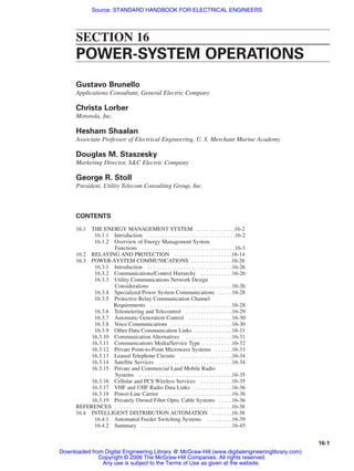
- 21. POWER-SYSTEM OPERATIONS 16-21 With this concept, large differential currents during external faults are ignored and the relay is sen- sitive for small differential current of internal faults. Ground Faults. Stator faults involving conductor contact with grounded elements may cause essentially no current flow or current comparable to phase-fault levels, depending on the system neu- tral grounding. Most large machines are unit-connected, meaning the turbine, the generator, and the transformer are treated as a unit, with no fault switching at generator voltage level. The low-voltage winding of the unit transformer is delta-connected, providing zero-sequence isolation from all other segments of the power system. The generator neutral is grounded through a high-impedance circuit, usually a distribution transformer loaded with a secondary resistor. This combination limits ground- fault current to a few amperes, which is undetectable by the generator differential relay. With this widely used grounding method, the generator neutral shift is dependent on fault location. A ground fault at a generator terminal will cause full line-to-neutral voltage to exist between neutral and ground. The closer the fault to the neutral, the lower is the magnitude of this voltage. A relay connected across the secondary terminals of the distribution transformer will be able to detect this voltage. It can be given sufficient sensitivity to detect faults from the line terminal down to approximately 4% of the neutral. It must ignore the normal third harmonic voltage, neutral to ground, to achieve this sensitivity. The protection just described is blind to faults very close to the neutral point and consideration shall be given to complement with other relays or replace it with another principle. These schemes use the third harmonic voltage neutral to ground and sense its absence for a neutral-to-ground fault, or they interject a current at another frequency and supervise its level. Neutral-to-ground faults rarely occur and, in themselves, are of no consequence. A second ground fault not only will go undetected with neutral-to-ground fundamental-voltage-detection but also may destroy the generator. Unbalanced Faults. Inherent in unbalanced faults is the fact that negative-sequence current is present. Flux associated with negative sequence rotates in a direction opposite to rotor rotation. This causes appreciable current flow in rotor structural parts that are not designed for such current, and excessive heating occurs. A relay designed to respond in a similar way to the machine is applied for this protective function. It is I2 2 t responsive, where I2 is per-unit negative-sequence current (on the machine full-load current base) and t is time in seconds. Generators vary in capability from I2 2 t of 5 to 40 for negative-sequence currents in excess of full load, depending on the type and size of machine. The negative-sequence current relay protects the generator against a prolonged contribution to an unbalanced fault beyond the generator breaker. It often contains provision for “alarming” at a lower level than the tripping level to annunciate the hazard of a sustained unbalanced current condition. Loss of Field. Field failure caused by any event, such as loss of regulator, opening of field breaker, field short, or field open, will cause a large var flow into the machine and generally a sub- stantial reduction in terminal voltage. This may or may not seriously jeopardize the machine, or it may jeopardize the stability of other adjacent machines. It requires detection and removal of the machine from the system. Most loss-of-field devices utilize generator terminal voltage and phase current to obtain impedance and phase angle. Loss of field causes impedance at the relay to decrease and current to lead more. This FIGURE 16-10 Typical differential protection for generator. Beaty_Sec16.qxd 17/7/06 8:50 PM Page 16-21 Downloaded from Digital Engineering Library @ McGraw-Hill (www.digitalengineeringlibrary.com) Copyright © 2006 The McGraw-Hill Companies. All rights reserved. Any use is subject to the Terms of Use as given at the website. POWER-SYSTEM OPERATIONS
- 22. phenomenon is usually detected by “distance” relays as shown in Fig. 16-11. Apparent ohms as viewed from the machine terminals enter the characteristic circle of the relay, causing it to operate. All such relays are equipped with time delay to avoid undesired tripping on power swings. Some contain directional and undervoltage units to permit additional sensitivity to partial loss of field and allow coordination with regulator minimum excitation units, the machine capability curve, and the steady-state stability curve. Field Ground. A single field ground causes no machine distress. Allowed to go uncorrected until a second field ground occurs, it can cause sufficient magnetic unbalance to produce cata- strophic vibration. For “brush-type” machines, detection of the first ground is usually accomplished by detecting current flow in a high-impedance dc-measuring circuit to ground. AC is also used in other devices through the introduction of an ac voltage between the dc field circuit and ground and monitoring the low-magnitude normal current that is allowed to flow. Where a “brushless” arrangement is used, no normal access exists to the field circuit because there are no nonrotating parts at field voltage level as there are in brush-type machines. Monitoring for grounds is achieved by periodically dropping, manually or automatically, pilot brushes onto collector rings provided for the purpose. One collector is connected to the neutral of the 3-phase ac exciter, and the other is connected to the rotor structure itself. Measurement of the voltage between these two points with an overvoltage relay allows detection of a ground fault at any point in the field circuit. Instability. When the electrical center appears to be in the transmission system, distance relays applied to protect the transmission lines can be used to detect instability and to separate the two sys- tem parts. This usually can be done discriminatingly with out-of-step blocking at some locations and tripping at others, all done in the interests of maintaining as nearly as possible a generation-load match after the separation. On the other hand, when the electrical center falls in the unit transformer or in the machine, the normal complement of relays applied to generator or transformer protection either will not detect the out-of-step condition or will be time delayed to the point of being unreliable for this function. In these cases, out-of-step relaying is applied. Figure 16-12 demonstrates the system behavior for a fault condition and for an out-of-step con- dition as viewed from the machine terminals and plotted in terms of a resistance-reactance diagram. Advantage is taken of the fact that emergence from the area between the blinder lines is on the same 16-22 SECTION SIXTEEN FIGURE 16-11 Detection of generator loss of field by measurement of impedance. Beaty_Sec16.qxd 17/7/06 8:50 PM Page 16-22 Downloaded from Digital Engineering Library @ McGraw-Hill (www.digitalengineeringlibrary.com) Copyright © 2006 The McGraw-Hill Companies. All rights reserved. Any use is subject to the Terms of Use as given at the website. POWER-SYSTEM OPERATIONS
- 23. side as entry for normal fault clearing and on the opposite side from entry for an out-of-step condi- tion. A blinder-type out-of-step relay trips for the latter case. Other Protection. For large, important units, relaying is included to detect motoring of the gen- erator, inadvertent energization when the machine is at standstill, excessive volts per hertz that in turn causes excessive transformer and generator iron heating, stator and field overcurrent, and any malfunction not detected by the first line relaying (i.e., backup must be included to prevent cata- strophic failure in the event of protective device malfunction). Small-Machine Protection. Much individual preference goes into the choice of protective equip- ment for small machines. For the very small, only voltage-restrained or supervised overcurrent relays may be used. In some cases only over- or undervoltage and frequency detection is applied. In other cases, protection approaching that for larger machines is used. In some cases, compromises with the more elaborate protection are used. For very small machines, time-delayed overcurrent relays with insensitive settings are used in the differential con- figuration. Specially connected watt relays are used for a combination loss-of-field and out-of-step detection function. Modern microprocessor packages contain most or all of the relaying functions necessary for generator protection plus monitoring, fault recording, and oscillography. They provide very low burden, self-checking, and greatly reduced panel-space requirements. Motor Protection. Both synchronous and induction motors have protective requirements similar to those of generators. One important difference is that motors are accelerated by applying full or reduced voltage to their terminals, while generators are brought up to speed by their prime mover before being connected to the power system. Large starting current, then, is a normal expected phe- nomenon associated with motors that generators do not experience. Both types of devices contribute to external phase faults. Motor neutrals are not generally grounded, so no ground current will flow in an unfaulted motor. POWER-SYSTEM OPERATIONS 16-23 FIGURE 16-12 Blinder scheme for generator out-of-step detection. Beaty_Sec16.qxd 17/7/06 8:50 PM Page 16-23 Downloaded from Digital Engineering Library @ McGraw-Hill (www.digitalengineeringlibrary.com) Copyright © 2006 The McGraw-Hill Companies. All rights reserved. Any use is subject to the Terms of Use as given at the website. POWER-SYSTEM OPERATIONS
- 24. Any protective device applied to protect a motor must ignore the conditions of starting current, load, and “through-fault” current, at the same time being able to sense low-magnitude internal-fault current. Differential relays perform this function well, often using a through-type current transformer with the two leads associated with each phase physically inserted through the ct window. Equal in- and-out currents generate no secondary voltage, so no operation of the relay connected to the ct sec- ondary occurs. Internal faults cause unequal currents which generate a secondary voltage to cause instantaneous relay tripping. For larger motors, differential relaying schemes identical to those used for generators are used for phase-fault detection. A ground-relaying variation of the “through-type ct” scheme requires that all 3-phase conductors be inserted through the ct window. Only ground faults on the motor side of the ct can cause the relay to operate. This is a widely used scheme. Another important element for detecting a fault in a motor is an instantaneous-trip phase device. It must, of course, be set above motor starting current, but available phase-fault current magnitude usually will greatly exceed the starting current magnitude, and very effective use can be made of this inexpensive and simple device. Thermal Protection. Motors are usually equipped with devices that detect and relieve motor overloading. These are either devices that experience a heating effect comparable with that of the motor itself and act accordingly or are relays that detect the temperature of a resistance-temperature detector (RTD) (through a measurement of its resistance) embedded between conductors in the sta- tor slot. As the motor temperature increases beyond the allowable level, the RTD resistance rises, and tripping of the controller takes place. Modern digital relays provide sophisticated models for the thermal behavior of the motor that operates when the thermal capability is violated. Locked-Rotor Protection. Neither of the relays used for thermal protection will, in general, pro- tect a motor with a locked rotor. A time overcurrent relay receiving one phase current will normally perform this locked-rotor protective function adequately. In some special large-motor applications where permissible locked-rotor time is less than the required starting time, distance relays have been used successfully to run timers to protect for the locked-rotor condition based on a measurement of a combination of motor impedance and phase angle. Unbalance Protection. Any degree of voltage unbalance at the motor terminals will manifest itself in the form of increased heating in the motor, well beyond that which could be predicted from the increase in stator current. This can be sensed by a relay which measures voltage unbalance or negative-sequence voltage. Buses that supply a large number of motors are usually equipped with this kind of protection. Phase-current magnitude comparison also has been used very successfully on circuits supplying a single large motor. Synchronous-Motor Protection. Because of the unique characteristics of synchronous motors, they are usually equipped with loss-of-field and out-of-step protection. This is often provided by a relay responsive to volt-amperes at an angle representative of the var flow into the motor on loss of field. It also will respond on loss of synchronism if the rate of pole slippage is compatible with the relay operating time or if the relay has a delayed resetting characteristic. Transformer Relaying. Protection of large transformers generally consists of differential protec- tion, gas space or oil rate-of-rise of pressure, or gas accumulation detection plus time overcurrent relays for backup. Differential Relaying. The differential-relaying concept is applicable to transformer protection in a manner similar to that for generator protection, but distinct differences exist. While current transformers having essentially identical ratios and characteristics are obtainable in generator pro- tection, no such identity is possible with the ct’s used in transformer protection. Inherently, they must have different ratios and probably will have quite different characteristics. Also, inrush cur- rent on initial energization and following external fault removal is a very real phenomenon that must be accommodated by the transformer differential relay. These two circumstances, different ct’s and inrush, makes the transformer differential relay different from the one described for the generator. In addition to the fact that “through” conditions such as load or external faults produce different currents on the two sides of the transformer (to cause equal ampere turns in the windings), for a wye-delta 16-24 SECTION SIXTEEN Beaty_Sec16.qxd 17/7/06 8:50 PM Page 16-24 Downloaded from Digital Engineering Library @ McGraw-Hill (www.digitalengineeringlibrary.com) Copyright © 2006 The McGraw-Hill Companies. All rights reserved. Any use is subject to the Terms of Use as given at the website. POWER-SYSTEM OPERATIONS
- 25. or delta-wye transformer there is also a phase shift between the line currents on the two sides. Further, the standard ratios of ct’s (such as 1200:5, 600:5, 100:5) used on the two sides of the transformer do not generally produce equal secondary currents for comparison by the differential relays for through conditions. As a result of these considerations: 1. Delta-side ct’s are connected in wye. 2. Wye-side ct’s are connected in delta. 3. Balance of input currents in the ratio of as much as 3:1 may be done inside the relay. 4. Inrush current is distinguished from internal-fault current in most transformer differential relays by using all harmonics, a combination of harmonics, or second harmonic only for inrush restraint. 5. Restraint is produced in proportion to the magnitude of the through current causing the relay to be sensitive at low current where ct error is likely to be low and to be insensitive at high current where ct error will be higher. Microprocessor relays are able to perform these functions, previously assigned to electro- mechanical and solid-state relays. They allow all the current transformers to be connected in wye, irrespective of the protected transformer connection, through the use of an algorithm that supplies the appropriate phase shifting. This permits retention of phase designations for the monitoring and oscillographic display. A widely used scheme for protecting a wye winding of a transformer against ground faults is shown in Fig. 16-13. The auxiliary trans- former is carefully chosen with a ratio that will minimize the effect of ct error for external faults and force a restraint condition (currents not flowing into the winding polarity markers simultaneously) to exist. Internal faults pro- duce a reversal in the operating current direc- tion with respect to the polarizing (reference) current direction causing the relay to operate. Another common application uses a time over- current relay supplied by a neutral ct connected in a wye-winding ground connection. It must be time-coordinated with other ground relays on the power system connected to the wye winding. Where differential relays are used, the primary function of this neutral ground relay is to back up these other devices. A neutral-ground relay may accomplish a primary (or first-line) relaying function where low-resistance grounding is used and high-voltage fuses are used. The typical fuse size required for full-load capability will not detect a low-voltage winding failure to ground in such a case. The ground relay will, depending on fault-current level. Remote tripping of a breaker feeding the fused trans- former will be required. Tripping of a low-voltage breaker will not clear this type of fault. Rate of Rise of Pressure or Gas Accumulation. Depending on whether a transformer is designed to have a nitrogen space above oil or to have a “conservator tank” and be completely filled with oil, use will be made of a rate of rise of gas pressure or a rate of rise of oil pressure device in larger transformers. Normal load cycling causes pressure change, but the rate of change is moder- ate. Faults under oil cause a much higher rate of change, and this distinction allows this type of device to distinguish between load change and faults. Gas-accumulation relays collect any gas gen- erated under oil by arcing or excessive temperature and base their fault detection on the extent of this collection. POWER-SYSTEM OPERATIONS 16-25 FIGURE 16-13 Transformer wye-winding differential protection. Beaty_Sec16.qxd 17/7/06 8:50 PM Page 16-25 Downloaded from Digital Engineering Library @ McGraw-Hill (www.digitalengineeringlibrary.com) Copyright © 2006 The McGraw-Hill Companies. All rights reserved. Any use is subject to the Terms of Use as given at the website. POWER-SYSTEM OPERATIONS
- 26. 16.3 POWER-SYSTEM COMMUNICATIONS BY GEORGE R. STOLL 16.3.1 Introduction Power-system communications play a vital role in the safe and efficient operation of the electric power grid. Real-time automation and control of electric utility generation, transmission and distribution sys- tems are dependent upon reliable and secure communication networks. Through an ever-expanding role, the communications’ networks enable the application of more computer and microprocessor- controlled devices. These networks and devices support the better utilization of extensive EMS and corporate information technology infrastructure. In addition, they enable the provision of new energy- related services and enhance the reliability and the safety of personnel and equipment. Power-system communications application typically support various elements of a power utility’s control, planning, accounting, and administrative functions. With deregulation of the U.S. electric utility environment, additional functions, including the marketing of bulk electric energy and trans- mission line access is also required. This section will primarily address communication functions and the systems they support for power-system operations. The operation functions have certain communication requirements that are unique to the electric utility industry. Many of the other utility telecommunication functions, such as administrative voice and data, have communication requirements similar to those of other large busi- ness enterprises. 16.3.2 Communications/Control Hierarchy Most power systems are vertically integrated; they perform the functions of generation, transmission and distribution, typically owned by the same entity. With deregulation, this model is in transition and ownership, and operations responsibilities vary with the country, the type of ownership and the size of the utility. In the United States today, the power marketing function (including the schedul- ing of generation, sale of bulk energy and transmission line capacity) has been separated from the transmission grid operations. This is to allow for an independent, nonbiased marketing of energy and transmission line capacity in a competitive market place. Previously, these functions were integrated into the same dispatch and operations center and frequently performed by the same personnel. While deregulation is changing the way many companies are organized and requiring more com- munications infrastructure, the basic communications functions between the various control centers, generating facilities, transmission, and distribution elements are fundamentally similar. Figure 16-14 is a simplified overview of the current U.S. model, illustrating the relationship between major power- system elements along with their communication requirements. 16.3.3 Utility Communications Network Design Considerations Most private utility optical and microwave wide area networks use time division multiplex (TDM) as the means for allocating a portion of a network’s bandwidth to an individual circuit. By imple- menting a high sampling rate for each individual circuit, a very high quality, low delay (also termed low latency) channel can be transported over the private network. This high-quality and low-latency circuit format is well suited to the mission critical and oftentime sensitive circuit requirements of an electric utility. And, this is not unlike the common carrier and public network cable, wireless and optical transport schemes used until recently. With the advent of the Internet and associated technologies, wide acceptance of a form of packet- switching protocol, termed Internet Protocol (IP), is starting to become widely used in wide area, public communication networks. Unlike TDM circuits, a packet circuit is not continuously con- nected. The packet circuit divides the information to be sent into packets, and each packet may take a different route through the network (or series of networks) to reach its destination. At the destination, 16-26 SECTION SIXTEEN Beaty_Sec16.qxd 17/7/06 8:50 PM Page 16-26 Downloaded from Digital Engineering Library @ McGraw-Hill (www.digitalengineeringlibrary.com) Copyright © 2006 The McGraw-Hill Companies. All rights reserved. Any use is subject to the Terms of Use as given at the website. POWER-SYSTEM OPERATIONS
- 27. 16-27 FIGURE 16-14 Interconnected power-systems—telecommunications requirements U. S. model. Beaty_Sec16.qxd 17/7/06 8:50 PM Page 16-27 Downloaded from Digital Engineering Library @ McGraw-Hill (www.digitalengineeringlibrary.com) Copyright © 2006 The McGraw-Hill Companies. All rights reserved. Any use is subject to the Terms of Use as given at the website. POWER-SYSTEM OPERATIONS
- 28. the packets are assembled into a sequence matching the information originally transmitted. When no information is being transmitted, no network resources are utilized. This feature allows other users of the network to use its capability, or share the resource and thus increase its efficiency when used for less time critical data transmissions. However, the disassembly, transmission time and reassembly of packets of information over IP networks add latency to all information being transmitted. Depending on the quality and capacity of the IP network and other technical factors, the information transmitted may be delayed anywhere from tens of milliseconds to several seconds. While acceptable for many types of data and even voice, these delays are not acceptable for many types of power-system operation channels. This does not mean that IP cannot be used to implement operations circuits. With the use of sig- nificant additional bandwidth, IP formats can be transported with the latency and constant delay required. With excessive bandwidth, TDM circuits can be emulated over IP. However, this is typi- cally only implemented over optical fiber networks where the utility manages the network. Because of the low cost of IP equipment and the availability of private utility company fiber networks with much more bandwidth than microwave, more IP networks for utility communication systems will be implemented in the future. 16.3.4 Specialized Power System Communications In addition to the voice and data network communications typical in many multifacility industrial or business complexes, there are communication requirements unique to the electric power industry. These include: • Protective relay Transmission line protection High-voltage switching equipment protection Generator and transformer protection • Telemetering and telecontrol Analog and digital telemetering SCADA Remote alarms AGC Remote metering––real-time metering––revenue metering • Voice communications Dedicated dispatch phones Two-way radio dispatch • Other data communication links Computer to computer links Open access same time information system (OASIS) and the Internet Regional transmission organizations 16.3.5 Protective Relay Communication Channel Requirements Protective relaying is unique in that the communications channel is faced with very stringent secu- rity and reliability requirements. Security requires that the communication channel never cause a false trip output. Reliability requires that the channel always be in service and function when needed. This requirement must be met even as the communication equipment is subjected to the harsh elec- tronic environment present at substations, switchyards, and generating plants. Protective relay equip- ment must operate during and after a fault condition and in the presence of electrical noise, ground potential rise, and transient voltages common to these environments. In addition, the communication channel must not add excessive time delay to the overall pro- tective relaying function. Where the electrical circuit breaker is located at a remote location from the sensing relays, the channel is usually allocated up to 16 ms (about the time required for one 16-28 SECTION SIXTEEN Beaty_Sec16.qxd 17/7/06 8:50 PM Page 16-28 Downloaded from Digital Engineering Library @ McGraw-Hill (www.digitalengineeringlibrary.com) Copyright © 2006 The McGraw-Hill Companies. All rights reserved. Any use is subject to the Terms of Use as given at the website. POWER-SYSTEM OPERATIONS