
Recommended
More Related Content
What's hot
What's hot (20)
Similar to Internal combustion engine
Similar to Internal combustion engine (20)
Recently uploaded
Recently uploaded (20)
Internal combustion engine
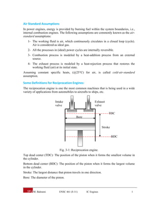
- 1. M. Bahrami ENSC 461 (S 11) IC Engines 1 Air Standard Assumptions In power engines, energy is provided by burning fuel within the system boundaries, i.e., internal combustion engines. The following assumptions are commonly known as the air- standard assumptions: 1- The working fluid is air, which continuously circulates in a closed loop (cycle). Air is considered as ideal gas. 2- All the processes in (ideal) power cycles are internally reversible. 3- Combustion process is modeled by a heat-addition process from an external source. 4- The exhaust process is modeled by a heat-rejection process that restores the working fluid (air) at its initial state. Assuming constant specific heats, (@25°C) for air, is called cold-air-standard assumption. Some Definitions for Reciprocation Engines: The reciprocation engine is one the most common machines that is being used in a wide variety of applications from automobiles to aircrafts to ships, etc. Fig. 3-1: Reciprocation engine. Top dead center (TDC): The position of the piston when it forms the smallest volume in the cylinder. Bottom dead center (BDC): The position of the piston when it forms the largest volume in the cylinder. Stroke: The largest distance that piston travels in one direction. Bore: The diameter of the piston. Intake valve Exhaust valve TDC BDC Stroke Bore
- 2. M. Bahrami ENSC 461 (S 11) IC Engines 2 Clearance volume: The minimum volume formed in the cylinder when the piston is at TDC. Displacement volume: The volume displaced by the piston as it moves between the TDC and BDC. Compression ratio: The ratio of maximum to minimum (clearance) volumes in the cylinder: TDC BDC V V V V r min max Mean effective pressure (MEP): A fictitious (constant throughout the cycle) pressure that if acted on the piston will produce the work. Wnet = MEP x APiston x Stroke = MEP x Displacement vol. kPa VV W MEP net minmax An engine with higher MEP will produce larger net output work. Internal Combustion Engines 1. spark ignition engines: a mixture of fuel and air is ignited by a spark plug applications requiring power to about 225 kW (300 HP) relatively light and low in cost 2. compression ignition engine: air is compressed to a high enough pressure and temperature that combustion occurs when the fuel is injected applications where fuel economy and relatively large amounts of power are required
- 3. M. Bahrami ENSC 461 (S 11) IC Engines 3 Spark‐Ignition (Gasoline) Engine Fig. 3-2: Actual cycle for spark-ignition engines, four-stroke. Fig. 3-3: P-v diagram for spark-ignition engines. Otto Cycle The Otto cycle is the ideal cycle for spark-ignition reciprocating engines. It serves as the theoretical model for the gasoline engine: Consists of four internally reversible processes Heat is transferred to the working fluid at constant volume The Otto cycle consists of four internally reversible processes in series: 1-2 Isentropic compression 2-3 Constant-volume heat addition Air +Fuel Compression stroke (1-2) Power (expansion) stroke (2-3) Combustion products Exhaust stroke (3-4) Intake stroke (4-1) Spark v
- 4. M. Bahrami ENSC 461 (S 11) IC Engines 4 3-4 Isentropic expansion 4-1 Constant-volume heat rejection Fig. 3-4: T-s and P-v diagrams for Otto cycle. The Otto cycle is executed in a closed system. Neglecting the changes in potential and kinetic energies, the 1st law, on a unit mass base, can be written: 1/ 1/ 111 :writtenbecanefficiencyThermal where / 232 141 23 14 , 1414 2323 TTT TTT TT TT q q q w TTcuuq TTcuuq kgkJuwwqq in out in net Ottoth vout vin outinoutin Processes 1-2 and 3-4 are isentropic, and v2 = v3 and v4 = v1. Thus, 1, 3 4 1 4 3 1 1 2 2 1 1 1 kOttoth kk r T T v v v v T T where r is called the compression ratio: 2 1 2 1 min max v v V V V V r Typical compression ratios for spark-ignition engines are between 7 and 10. The thermal efficiency increases as the compression ratio is increased. However, high compression ratios can lead to auto ignition or engine knock. T s1 2 3 4v = Const. v = Const. Qin Qout 1 2 3 4 Isentropic Isentropic P TDC BDC v
- 5. M. Bahrami ENSC 461 (S 11) IC Engines 5 Diesel Engine The Diesel cycle is the ideal cycle for compression ignition engines. It is very similar to spark-ignition, expect the method of ignition. In diesel engine, air compressed to a temperature that is above the ignition temperature of the fuel. Fig. 3-5: T-s and P-v diagram of Diesel engine. The thermal efficiency of the Diesel engine under the cold air standard assumptions becomes: 2 1 min max Ottofor1 1, where 1 11 1 v v V V r rk r rq w c k c k in net Dieselth We also define the cutoff ratio rc, as the ratio of cylinder volumes after and before the combustion process (ignition period): 2 3 2 3 v v V V rc Comparison of the Otto and the Diesel Cycle ηOtto > ηDiesel for the same compression ratio Diesel engines burn the fuel more completely since they usually operate at lower rpm and air-fuel ratio is much higher than ignition-spark engines Diesel engines compression ratios are typically between 12 and 24, whereas spark-ignition (SI) engines are between 7 and 10. Thus a diesel engine can tolerate a higher ratio since only air is compressed in a diesel cycle and spark knock is not an issue T s1 2 3 4 P = Const. P = Const. Qin Qout 1 2 3 4 Isentropic Isentropic P v TDC BDC
- 6. M. Bahrami ENSC 461 (S 11) IC Engines 6 Dual Cycle (Limited Pressure Cycle) Combustion process in internal combustion engines either as constant-volume (Otto cycle) or constant-pressure (Diesel cycle) heat addition is overly simplified and it is not realistic. dual cycle is a better representation of the combustion process in both the gasoline and the diesel engines both the Otto and the Diesel cycles are special cases of the dual cycle. Fig. 3-6: T-s and P-v diagrams for an ideal dual cycle. Defining: 1Dual 2 3 3 4 2 1 11 1 1 :becomescycledualtheofefficiencythermalThe ratioPressure ratioCutoff rationCompressio k cpp k cp p c rrkrr rr P P r v v r v v r Note that when rp =1, we get the Diesel engine efficiency. 1 2 3 4 5 v = Const. P = Const. v = Const. s T 1 2 3 4 5 P QH,2 QH,1 Isentropic Isentropic