1. Induction Motor Speed Torque Characteristics.
When applying VARIABLE Frequency Drives(VFD), the speed-torque
characteristics of an induction motor started at full voltage and operated on
utility power should first be reviewed.
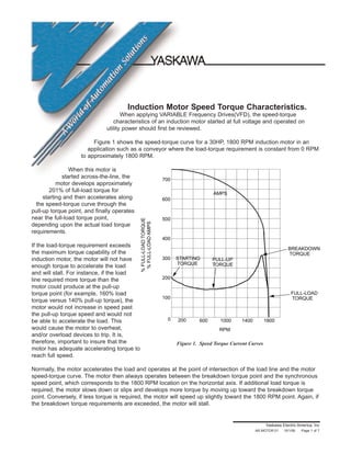
Figure 1 shows the speed-torque curve for a 30HP, 1800 RPM induction motor in an
application such as a conveyor where the load-torque requirement is constant from 0 RPM
to approximately 1800 RPM.
When this motor is
started across-the-line, the
motor develops approximately
201% of full-load torque for
starting and then accelerates along
the speed-torque curve through the
pull-up torque point, and finally operates
near the full-load torque point,
depending upon the actual load torque
requirements.
If the load-torque requirement exceeds
the maximum torque capability of the
induction motor, the motor will not have
enough torque to accelerate the load
and will stall. For instance, if the load
line required more torque than the
motor could produce at the pull-up
torque point (for example, 160% load
torque versus 140% pull-up torque), the
motor would not increase in speed past
the pull-up torque speed and would not
be able to accelerate the load. This
would cause the motor to overheat,
and/or overload devices to trip. It is,
therefore, important to insure that the
motor has adequate accelerating torque to
reach full speed.
Normally, the motor accelerates the load and operates at the point of intersection of the load line and the motor
speed-torque curve. The motor then always operates between the breakdown torque point and the synchronous
speed point, which corresponds to the 1800 RPM location on the horizontal axis. If additional load torque is
required, the motor slows down or slips and develops more torque by moving up toward the breakdown torque
point. Conversely, if less torque is required, the motor will speed up slightly toward the 1800 RPM point. Again, if
the breakdown torque requirements are exceeded, the motor will stall.
Yaskawa Electric America, Inc
AR.MOTOR.01 10/1/06 -Page 1 of 7
700
600
500
400
300
200
100
0 200 600 1000 1400 1800
RPM
%FULL-LOADTORQUE
%FULL-LOADAMPS
STARTING
TORQUE
PULL-UP
TORQUE
AMPS
BREAKDOWN
TORQUE
FULL-LOAD
TORQUE
Figure 1. Speed Torque Current Curves
2. Yaskawa Electric America, Inc
AR.MOTOR.01 10/1/06 Page 2 of 7
Induction Motor
Speed Torque Characteristics
Typically, when a NEMA Design B induction motor is started across-the-line, an inrush current of 600 to 800% FLA occurs,
corresponding to the starting torque point. As the load is accelerated to the full-load torque point, the current decreases to
100% full-load current at 100% full-load torque. High currents, however, are drawn during acceleration time.
The amount of time that the motor takes to accelerate the load will depend on the average accelerating torque, which is the
difference between the motor speed-torque curve and the load speed-torque curve, and is the torque available to accelerate
the load inertia.
Figure 2 is an enlarged detail of the region between the breakdown torque point and the synchronous speed point, which is
where the motor would operate. This is of particular
interest because the current for the various torque
requirements can easily be seen. This would directly
affect the size of the adjustable frequency drive
required to produce a given torque, because the drive is
current rated.
At 100% full-load torque, 100% full-load nameplate
current is required. At 150% torque, 150% full-load
nameplate current is required. Beyond the 150% full-
load torque point, however, the torque-per-amp ratio is
no longer proportional. For this case, 313% breakdown
torque would require 450% current.
The number of poles is a function of how the motor is
wound. For example, for 60 Hertz power, a two pole
motor would operate at 3600 RPM, a four pole motor
at 1800 RPM, and a six pole motor at 1200 RPM.
Magnetic
Poles RPM
2 3600
4 1800
6 1200
8 900
10 720
400
300
200
100
0 1680 1720 1760 1800
RPM
%FULL-LOADTORQUE
%FULL-LOADAMPS
TORQUE
AMPS
Figure 2. Torque Current Curves
3. The actual or running speed of an induction motor is
influenced by the applied load and the resultant slip. The
torque the motor produces is also a function of slip; more
slip, more torque. A NEMA Design B motor generally
operates at 3% slip, or 50 RPM of slip.
Speed µ Frequency x 120 - Slip
Poles
At 3% slip, the motor will produce its rated torque. The
motor can slip further, with resultant increase in torque. This
would continue until the breakdown peak, at which time the
motor would stall. Other motor designs such as NEMA D
can slip as much as 13% at full load.
The horsepower and torque output of an induction motor
can be calculated by these formulas:
RPM x Torque
HP = 5250
HP x 5250
Torque = RPM
With all of the formulas now explained, they can be applied
to a motor in an actual situation, to see how changes in
voltage and frequency affect operation.
- - - - - U.S. OPERATION - - - - -
30 HP 460 VAC
1800 RPM 60 Hertz
89.4 lb-ft torque 69 Amps
In simple terms, the variables of operation are:
– Voltage controls power output or HP
– Frequency controls speed or RPM
– Current controls torque.
If the same motor is used in Europe, which has a different
power grid than in the U.S. (most of Europe operates at 380
VAC, 50 Hertz), the following conditions would be noted:
- - EUROPEAN OPERATION - -
25 HP 380 VAC
1500 RPM 50 Hertz
89.4 lb-ft torque 69 Amps
The fixed speed motor can be operated at another line
voltage because the ratio of voltage and frequency remained
the same. This can be referred to as the volts/Hertz ratio for
which the motor is wound.
460/60 = 7.7 V/Hz 380/50 = 7.7 V/Hz
If the motor is operated at 575 VAC at 60 Hertz, it would
overexcite or saturate, burning up.
At 230 VAC at 60 Hertz, it would be underexcited and stall
due to high induced currents. This formula explains this
phenomenon:
Magnetic Flux
Torque µ Density Within µ Volts/Hertz
Motor Air Gap
In order to vary the speed of an induction motor, the drive
would have an output characteristic as shown in Figure 3.
The voltage is varied directly with the frequency,
maintaining a constant V/Hz ratio. For instance, a 460 volt
Yaskawa drive would typically be adjusted (i.e.
programmed) to provide 460 volts output at 60 Hertz and
230 volts at 30 Hertz.
Yaskawa Electric America, Inc
AR.MOTOR.01 10/1/06 Page 3 of 7
Induction Motor
Speed Torque Characteristics
460
345
230
115
0
15 30 45 60
FREQUENCY (Hz)
OUTPUTVOLTAGE
Figure 3. Drive Output
4. The drive would typically start an induction motor by starting at low voltage and low frequency and increasing the voltage
and frequency to the desired operating point. This would contrast to the typical way of starting induction motors by
applying full voltage (460 volts at 60 Hertz) immediately to the motor.
By starting the motor with low voltage and low frequency, the inrush current associated with across-the-line starting is
completely eliminated. In addition, the motor operates between the breakdown torque point and synchronous speed point as
soon as it is started, as compared to starting across-the-line in which case the motor accelerates to a point between the
synchronous speed and breakdown torque point.
The curve in Figure 4 shows the actual speed-torque curves which result when a motor is operated from a constant volts-
per-Hertz voltage source supply. When low voltage and low frequency is applied to the motor, the maximum torque
available decreases at reduced speeds. This is a result of the resistive voltage drop of the stator windings.
The motor would always operate between the maximum torque or breakdown torque point and the synchronous speed point
which is represented by the intersection with the horizontal axis.
As the applied motor voltage and frequency is increased from 0 volts and 0 Hertz, the motor speed torque curve moves to
the right as shown in Figure 4.
The maximum starting torque for constant volts-per-Hertz operation may actually be much less than full-load torque. This
may provide adequate torque for starting some
loads such as a centrifugal load, but other loads
such as a constant torque load will require higher
starting torques. This is achieved by applying a
voltage boost, or additional voltage, at low
frequency.
Yaskawa Electric America, Inc
AR.MOTOR.01 10/1/06 Page 4 of 7
Induction Motor
Speed Torque Characteristics
300
200
100
0 50 100
% SPEED
%FULL-LOADTORQUE
Figure 4. Speed Torque Curves
5. In order to obtain more starting torque, as shown in Figure 5, a voltage boost is applied at low frequency to overcome the
resistive drop of the motor at low frequency. This drop also occurs at higher frequencies, but has much less effect since it
becomes a smaller percentage of the applied voltage. This voltage boost
is typically around 5% of the motor full-load nameplate voltage.
The voltage boost can be adjusted to produce various levels of starting torque. Figure 5 shows the torque that would be
provided without boost and the torque that would be provided with voltage boost set to 150% starting torque.
The voltage boost should be adjusted to provide the required torque and to overcome the resistive drop of the motor. If this
voltage boost is too high, saturation could occur and cause high motor currents and excessive motor heating.
Figure 6 shows resultant speed/torque curves with voltage boost.
Yaskawa Electric America, Inc
AR.MOTOR.01 10/1/06 Page 5 of 7
Induction Motor
Speed Torque Characteristics
10
20
30
40
50
10
50
3020
100
150
3
FREQUENCY (Hz)
%FULL-LOADTORQUE
%VOLTAGE
TORQUE(%FULLLOAD)
BOOST
VOLTS/HERTZ
WITH BOOST
TORQUE
WITH BOOST
CONSTANT
VOLTS/HERTZ
TORQUE
WITHOUT BOOST
Figure 5. Starting Torque Characteristics
RPM
HZ
0
0
600
20
1200
40
1800
60
0
200%
175%
150%
125%
100%
75%
50%
25%
Figure 6. Adjustable Frequency Speed/Torque
6. Figure 7 shows the resulting motor/drive speed-torque curve for the range of operation below 100% speed which would
correspond to the 60 Hertz operating point. As a reference, the speed-torque/current curve of an induction motor started
across-the-line is also shown.
The dark line corresponding to the 100% full-load torque/current point represents the maximum continuous torque available
from the combined motor and VFD. The dashed line at 150% indicates the short-time current/torque rating of the drive.
At any given speed, the motor would operate as previously discussed between the maximum torque point and the
synchronous speed point. The amount of torque available would depend on the amount of current which could be supplied
by the drive.
As previously discussed, the starting torque characteristics and the maximum torque available from the motor/drive
combination may be different from the torque available when operating the motor from utility power and starting with full
voltage.
Yaskawa Electric America, Inc
AR.MOTOR.01 10/1/06 -Page 6 of 7
Induction Motor
Speed Torque Characteristics
700
600
500
400
300
200
100
0 200 600 1000 1400 1800
RPM
%FULL-LOADTORQUE
%FULL-LOADAMPS
STARTING
TORQUE
PULL-UP
TORQUE
AMPS
BREAKDOWN
TORQUE
FULL-LOAD
TORQUE
SHORT-TERM
TORQUE
Figure 7. Speed Torque Current Curves
7. The previous discussion was related to operation of an induction motor at 60 Hertz and below. When using a motor/motor
combination, the motor is no longer limited to 60 Hertz operation, and can actually be operated above 60 Hertz. Figure 8
shows the speed torque and horsepower curves for a motor and Yaskawa drive both below and above 60 Hertz.
The region below 60 Hertz is typically referred to as the constant torque range of operation, and the area above 60 Hertz is
generally referred to as the constant horsepower range of operation. Up to 60 Hertz, the voltage is varied directly with the
frequency. Above 60 Hertz, however, the voltage is fixed and only the frequency is increased.
It should be evident that in the constant horsepower region there is a decrease in available torque. This phenomenon is
explained by the same formula mentioned earlier:
Magnetic Flux
Torque µ Density Within µ Volts/Hertz
Motor Air Gap
As frequency increases, the V/Hz ratio decreases and torque follows.
For further details on operation in the constant horsepower region, refer to the LOAD PROFILES AD4011.
Yaskawa Electric America, Inc
AR.MOTOR.01 10/1/06 Page 7 of 7
Induction Motor
Speed Torque Characteristics
CONSTANT
TORQUE
CONSTANT
HP
TORQUE
HORSEPOWER
% SPEED
%FULL-LOADHORSEPOWER
%FULL-LOADTORQUE
FREQUENCY (Hz)
50%
30
100%
60
150%
90
100
50
Figure 8. Adjustable Frequency Motor Speed Torque Curve