
Recommended
Recommended
More Related Content
What's hot
What's hot (20)
Similar to Thin-walled column design considering local, distortional and euler buckling
Similar to Thin-walled column design considering local, distortional and euler buckling (20)
More from civilengineeringfreedownload
More from civilengineeringfreedownload (18)
Recently uploaded
Recently uploaded (20)
Thin-walled column design considering local, distortional and euler buckling
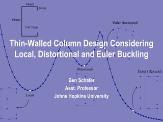
- 1. 34mm 64mm 8mm t=0.7mm Local Distortional Euler (torsional) Euler (flexural) Thin-Walled Column Design Considering Local, Distortional and Euler Buckling Ben Schafer Asst. Professor Johns Hopkins University
- 2. Overview • Introduction • Elastic Buckling • Ultimate Strength • Column Design Methods • Performance of Methods • Conclusion
- 3. Introduction 0 50 100 150 200 250 300 350 400 450 500 10 100 1000 10000 half-wavelength (mm) bucklingstress(MPa) 34mm 64mm 8mm t=0.7mm Local Distortional Euler (torsional) Euler (flexural)
- 4. Elastic Buckling Prediction • Numerical Methods – finite element, finite strip (www.ce.jhu.edu/bschafer) • Hand Methods (for use in a traditional Specification) – Local Buckling • Element methods, e.g. k=4 • Semi-empirical methods that include element interaction – Distortional Buckling • Proposed (Schafer) method, rotational stiffness at web/flange juncture • Hancock’s method • AISI (k for Edge Stiffened Elements per Spec. section B4.2)
- 5. Elastic Buckling Comparisons1 (fcr)element (fcr)interact (fcr)Schafer (fcr)Hancock (fcr)AISI All Data avg. 1.34 1.03 0.93 0.96 0.79 st.dev. 0.13 0.06 0.05 0.06 0.33 max 1.49 1.15 1.07 1.08 1.45 min 0.96 0.78 0.81 0.83 0.18 count 149 149 89 89 89 Schafer (1997) Members avg. 1.16 1.02 0.92 0.96 1.09 st.dev. 0.15 0.08 0.07 0.06 0.16 Commercial Drywall Studs avg. 1.38 1.07 0.93 1.00 0.81 st.dev. 0.09 0.05 0.02 0.07 0.26 AISI Manual C's avg. 1.33 1.01 0.93 0.99 0.81 st.dev. 0.13 0.07 0.05 0.03 0.26 AISI Manual Z's avg. 1.39 1.04 0.92 0.92 0.41 st.dev. 0.03 0.04 0.03 0.06 0.18 (fcr)true = local or distoritonal buckling stress from finite strip analysis (fcr)element = minimum local buckling stress of the web, flange and lip via Eq.'s 1-3 (fcr)interact = minimum local buckling stress using the semi-empirical equations (Eq.'s 4-6) (fcr)Schafer = distortional buckling stress via Eq.'s 7-15 (fcr)Hancock = distortional buckling stress via Lau and Hancock (1987) (fcr)AISI = buckling stress for an edge stiffened element via AISI (1996) from Desmond et al. (1981) Local Distortional (fcr)true (fcr)true (fcr)true (fcr)true (fcr)true (fcr)element (fcr)interact (fcr)Schafer (fcr)Hancock (fcr)AISI All Data avg. 1.34 1.03 0.93 0.96 0.79 st.dev. 0.13 0.06 0.05 0.06 0.33 max 1.49 1.15 1.07 1.08 1.45 min 0.96 0.78 0.81 0.83 0.18 count 149 149 89 89 89 Schafer (1997) Members avg. 1.16 1.02 0.92 0.96 1.09 st.dev. 0.15 0.08 0.07 0.06 0.16 Commercial Drywall Studs avg. 1.38 1.07 0.93 1.00 0.81 st.dev. 0.09 0.05 0.02 0.07 0.26 AISI Manual C's avg. 1.33 1.01 0.93 0.99 0.81 st.dev. 0.13 0.07 0.05 0.03 0.26 AISI Manual Z's avg. 1.39 1.04 0.92 0.92 0.41 st.dev. 0.03 0.04 0.03 0.06 0.18 (fcr)true = local or distoritonal buckling stress from finite strip analysis (fcr)element = minimum local buckling stress of the web, flange and lip via Eq.'s 1-3 (fcr)interact = minimum local buckling stress using the semi-empirical equations (Eq.'s 4-6) (fcr)Schafer = distortional buckling stress via Eq.'s 7-15 (fcr)Hancock = distortional buckling stress via Lau and Hancock (1987) (fcr)AISI = buckling stress for an edge stiffened element via AISI (1996) from Desmond et al. (1981) * *For members with slender webs and small flanges the Lau and Hancock (1987) approach conservatively converges to a buckling stress of zero (these members are ignored in the summary statistics given above) 1 For a wide variety of cold-formed steel lipped channels, zees and racks
- 6. Ultimate Strength • Numerical Studies (nonlinear FEA) – Analysis of isolated flanges – Parametric studies on lipped channels • Existing Experimental Data (pin ended, concentrically loaded columns) – 100+ tests on lipped channels – 80+ tests on lipped zees – 40 tests on rack columns (variety of stiffeners)
- 7. Numerical Studies on Ultimate Strength • Primarily focused on differences in the behavior and in the failure mechanisms associated with local and distortional buckling. • Key findings in this area: – distortional buckling may control the failure mechanism even when the elastic distortional buckling stress (fcrd ) is higher than the elastic local buckling stress (fcrl) – distortional failures have lower post-buckling capacity and higher imperfection sensitivity than local failures
- 8. Experiments on Distortional Buckling Failures High Strength Rack Columns (U. of Sydney) 0 0.5 1 1.5 2 2.5 3 3.5 4 4.5 5 0 0.2 0.4 0.6 0.8 1 channel rack rack+lip hat channel+web st. distortional slenderness (Fy/Fcr) .5 or (Py/Pcr) .5 strength(Fu/Fy)or(Pu/Py) 0 0.5 1 1.5 2 2.5 3 3.5 4 4.5 5 0 0.2 0.4 0.6 0.8 1 channel rack rack+lip hat channel+web st. distortional slenderness (Fy/Fcr) .5 or (Py/Pcr) .5 strength(Fu/Fy)or(Pu/Py) (a) (b) (c) (d) (e) 0 0.5 1 1.5 2 2.5 3 3.5 4 4.5 5 0 0.2 0.4 0.6 0.8 1 channel rack rack+lip hat channel+web st. distortional slenderness (Fy/Fcr) .5 or (Py/Pcr) .5 strength(Fu/Fy)or(Pu/Py) 0 0.5 1 1.5 2 2.5 3 3.5 4 4.5 5 0 0.2 0.4 0.6 0.8 1 channel rack rack+lip hat channel+web st. distortional slenderness (Fy/Fcr) .5 or (Py/Pcr) .5 strength(Fu/Fy)or(Pu/Py) (a) (b) (c) (d) (e) Eq. 16 not predicted by AISI Spec.
- 9. Considered Design Methods • Effective Width Methods – AISI Design Specification (1996) – Element by element effective width approach, local and distortional buckling treated separately • Direct Strength Methods – Hand solutions for member elastic buckling – Numerical solutions (finite strip) for elastic buckling • Varying levels of interaction amongst the failure modes considered (see paper for full discussion)
- 10. Effective Width Methods −= f f f f 22.01 b b crcreff for 673.0 f f cr > , else bbeff =.(17) where: beff is the effective width of an element with gross width b f is the yield stress (f = fy) when interaction with other modes is not considered, otherwise f is the limiting stress of a mode interacting with local buckling crf is the local buckling stress ∑= tbA effeff * * for Euler (long column) interaction f=Fcr of the column curve used in AISC Spec. (the notation for f is Fn in the AISI Spec. but the same column curve is employed)
- 11. Direct Strength Methods 4. cr 4. crn P P P P 15.01 P P −= for 776.0 P P cr > , else Pn = P . (19) where: Pn is the nominal capacity P is the squash load (P = Py = Agfy) except when interaction with other modes is considered, then P = Agf, where f is the limiting stress of the interacting mode. crP is the critical elastic local buckling load (Ag crf ) 6. crd 6. crdn P P P P 25.01 P P −= for 561.0 P P crd > , else Pn = P. (16) where: Pn is the nominal capacity in distortional buckling P is the squash load (P = Py = Agfy) when interaction with other modes is not considered, otherwise P = Agf, where f is the limiting stress of a mode that may interact Pcrd is the critical elastic distortional buckling load (Agfcrd) Local Distortional
- 12. Performance of Effective Width Methods (for subset of tests on lipped Zees) 0 20 40 60 0 20 40 60 80 100 120 d (mm) Pu(kn) experiment A1=AISI(1996) local by B1 distortional by B1 B1 0 20 40 60 0 20 40 60 80 100 120 d (mm) Pu(kn) L = 610 mm h ~ 200 mm b ~ 75 mm t = 1.5 mm L = 1220 mm h ~ 200 mm b ~ 75 mm t = 1.5 mm 0 20 40 60 0 20 40 60 80 100 120 d (mm) Pu(kn) experiment A1=AISI(1996) local by B1 distortional by B1 B1 0 20 40 60 0 20 40 60 80 100 120 0 20 40 60 0 20 40 60 80 100 120 d (mm) Pu(kn) experiment A1=AISI(1996) local by B1 distortional by B1 B1 0 20 40 60 0 20 40 60 80 100 120 d (mm) Pu(kn) L = 610 mm h ~ 200 mm b ~ 75 mm t = 1.5 mm L = 1220 mm h ~ 200 mm b ~ 75 mm t = 1.5 mm
- 13. Performance of Direct Strength Methods (for subset of tests on lipped Zees) 0 20 40 60 0 20 40 60 80 100 120 d (mm) Pu(kn) experiment A1=AISI(1996) local by B3 distortional by B3 B3 0 20 40 60 0 20 40 60 80 100 120 d (mm) Pu(kn) L = 610 mm h ~ 200 mm b ~ 75 mm t = 1.5 mm L = 1220 mm h ~ 200 mm b ~ 75 mm t = 1.5 mm 0 20 40 60 0 20 40 60 80 100 120 d (mm) Pu(kn) experiment A1=AISI(1996) local by B3 distortional by B3 B3 0 20 40 60 0 20 40 60 80 100 120 0 20 40 60 0 20 40 60 80 100 120 d (mm) Pu(kn) experiment A1=AISI(1996) local by B3 distortional by B3 B3 0 20 40 60 0 20 40 60 80 100 120 d (mm) Pu(kn) L = 610 mm h ~ 200 mm b ~ 75 mm t = 1.5 mm L = 1220 mm h ~ 200 mm b ~ 75 mm t = 1.5 mm
- 14. Overall Performance (Direct Strength) 0 1 2 3 4 5 6 7 8 0 0.2 0.4 0.6 0.8 1 1.2 1.4 1.6 local buckling controlled distortional buckling controlled slenderness of controlling mode (Pn/Pcr) .5 strengthPu/Pne Solution C3 0 1 2 3 4 5 6 7 8 0 0.2 0.4 0.6 0.8 1 1.2 1.4 1.6 0 1 2 3 4 5 6 7 8 0 0.2 0.4 0.6 0.8 1 1.2 1.4 1.6 local buckling controlled distortional buckling controlled slenderness of controlling mode (Pn/Pcr) .5 strengthPu/Pne Solution C3
- 15. Conclusions • Must consider local, distortional, and Euler modes, but closed- form and numerical methods are accurate and available • Current effective width based design methods ignore local web/flange interaction and distortional buckling, leading to systematic error and inflexibility in dealing with new shapes • A direct strength method using separate column curves for local and distortional buckling: – provides a consistent and accurate treatment of the relevant buckling modes – avoids lengthy effective width calculations – demonstrates the effectiveness of directly using numerical elastic buckling solutions – opens the door to rational analysis methods – provides greater potential innovation in cold-formed shapes