Beyond Boundaries: Leveraging No-Code Solutions for Industry Innovation
impmatch
1. Electus Distribution Reference Data Sheet: IMPMATCH.PDF (1)
IMPEDANCE MATCHING: A PRIMER
From time to time you’ll come across the term
‘impedance matching’ in various areas of electronics, and
especially in fields like RF and audio engineering.
However even in these fields it’s often misused, probably
because many people don’t really understand the
concepts behind it.
In this primer we’ll try to clarify what impedance
matching is really all about, why it’s important in some
situations — and not important in others.
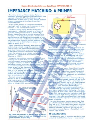
Textbooks usually explain the idea of impedance
matching with a very simple example of an electrical
generator feeding a resistive load, as shown in Fig.1.
Because the generator has an internal resistance of its
own (R G ) — as all real generators do — this tends to
dissipate some of the generator’s output power as heat, Fig.1: A generator driving a load resistance R L —
whenever we connect a load to its output terminals. So and its own internal resistance R G.
the full mechanical power fed into the generator can’t
be drawn from it as electrical power, because some will
impedance. And the idea of matching the load and
always be wasted in R G .
generator resistance became one of matching the source
When early electrical engineers were faced with this and load impedance — impedance matching .
problem, they naturally enough did everything they
Now this may sound simple and straightforward, but
could to reduce the internal resistance of their
it’s important to remember where the idea came from,
generators. However they were inevitably still left with
and also realise what exactly is going on when we do
SOME internal resistance, because it’s impossible to
match load and generator/source resistances or
reduce the resistance to zero unless you run the
impedances. True, the POWER transferred to the load
generator at a temperature of close to absolute zero
will be a maximum; but at the same time, the actual
(0Kelvins, or -273°C).
power being dissipated in the generator’s internal
Once they had minimised the internal resistance, their resistance is EXACTLY THE SAME as that reaching the
next step was to see if there was some way that they load! In other words, HALF the total power from the
could minimise the amount of power wasted in it, by generator is now being turned into heat inside R G ,
varying the resistance of the load. And what they because its resistance is now half the total connected
discovered is shown in the Fig.2, which plots the amount across the generator. The ‘other half ’ is the load
of power transferred into the load R L as its resistance is resistance R L .
varied. As you can see, the amount of power reaches a
For exactly the same reason, R G and R L will now be
peak or MAXIMUM when the load resistance is the
acting as a 2:1 voltage divider across the generator —
same as — or ‘matches’ the generator resistance. It falls
so that only HALF the generator’s output voltage (E G )
away for values both higher and lower than this figure,
will be appearing across the load. In terms of voltage
showing that matching the two is clearly desirable if we
transfer, then, matching the impedances isn’t particularly
want to maximise the power able to reach the load.
efficient: it actually gives a 6dB loss.
So this is where the idea of matching the resistance of
Does this mean that impedance matching really only
the load to that of the generator came from. Before
applies to generators in power stations? No, and in fact
long, it was extended to cover the general situation of
it doesn’t really apply there either — or at least, not
any load impedance connected to a source of electrical
simply. All it really means is that as you draw more and
energy or voltage (EMF), with its own internal source
more power from a generator by reducing the load
resistance, a point is reached where half the
generator’s output power is being wasted inside it.
Obviously with very high power generators it’s not a
good idea to load them even this heavily — let alone
dropping the R L even further, where even more power
is lost inside the generator than reaches the load. (See
the blue curve in Fig.2, showing the power lost in the
generator.) Most power station generators are loaded
with an R L somewhat higher than R G , to waste as little
power as possible.
So when IS impedance matching a good idea? Glad
you asked. Basically it’s for situations rather different
from that in Fig.1, where we’re stuck with a particular
load or cable impedance, and we still want to either
maximise the power transferred into the load, or
minimise the amount of power reflected back from it
into the cable, or both.
Fig.2: How the power fed to the load varies as the load RF CABLE MATCHING
resistance is varied (red plot), and what happens to the For example in many RF situations, we tend to have
power wasted in R G (blue plot). a relatively fixed LOAD impedance — say a resonant
2. Electus Distribution Reference Data Sheet: IMPMATCH.PDF (2)
quarter-wave antenna, with an impedance of
50 ohms resistive. To minimise interference
we also have to use coaxial cable to
connect the antenna to a transmitter or
receiver.
Now as you may be aware, coaxial cable
behaves as a transmission line at radio
frequencies, and as a result it has its own
characteristic impedance . This simply means
that because of the inductance-to-
capacitance (or L/C) ratio of the cable, RF
energy tends to move along it with a
particular ratio between the electric and
magnetic fields (i.e., voltage to current). Fig.3: A transmitter or other source of RF feeding power to an
In most cases when the energy reaches antenna, via a coaxial cable or other transmission line. Here’s
the end of the cable, we want as much as where impedance matching IS important...
possible to transfer into our load — the
antenna, in the case of a transmitter, or the
thing is to ensure that the transmitter output stage will
input RF stage in the case of a receiver. For a
feed as much RF energy as possible into the cable’s
transmitter this gives the highest power efficiency, while
input impedance. There can even be an advantage in
for a receiver it gives the best noise performance.
deliberately mismatching the impedances (i.e., having the
And guess what? To ensure this optimum energy transmitter impedance much lower than the cable), to
transfer, we need to match the characteristic impedance minimise power loss in the final stage and also ensure
of the cable to the impedance/resistance of the load. So that if RF is reflected back from the antenna end, most
for a 75Ω antenna or receiver input, we need to use of it is bounced right back up again. So this situation is a
75Ω coaxial cable. For a 50Ω antenna we need to use bit like the generator in a power station...
50Ω cable, and so on. (see Fig.3)
This, then, is an area where impedance matching IS VIDEO INTERCONNECTIONS
quite important. Because what happens if the cable and
antenna (or receiver) impedances are NOT matched is Now let’s consider another area where impedance
that some of the RF energy reaching the end of the matching again tends to be quite important: video
cable won’t be transferred into the load, but is interconnections. Here we’re dealing with signals which
REFLECTED back along the cable, towards the source. span from DC up to about 6MHz or so — well into the
This can set up standing waves in the cable (another ‘RF’ range. And we also tend to find ourselves using
cause of power loss, and possibly cable damage), and can coaxial cables, to reduce interference. So again we need
to match the cable impedance and the
load impedance, to prevent signal
reflection. With video, these reflections
can cause ringing and ghosting in the
final picture. (RingIng is multiple edges
on outlines in the picture, while
ghosting is multiple images — each
shifted horizontally.)
Most video equipment is designed to
be interconnected with 75Ω cables, and
has inputs which are designed to
present this same input impedance. So
matching tends to occur automatically,
providing you use the correct cables.
Fig.4: Video interconnections, where impedance matching is again How about video outputs — are
quite important. these impedance matched too? Yes,
generally they are, not because it
results in maximum signal transfer but
because with video signals we DON’T want any signal
also cause overheating in the transmitter output stage. reflected back from the load to be reflected back all
In a receiver, the mismatch degrades the effective over again — this would make ringing even worse. So
receiver gain and noise figure. often the video outputs of cameras, VCRs, DVD players
How do you ensure correct impedance matching in and so on are fitted with a 75Ω series resistor inside, to
this type of RF situation? Generally the cable impedance provide ‘back termination’ for the cable (Fig.4). This is
is more or less fixed, and the antenna impedance may be just another name for impedance matching at the source
the same. But quite a few techniques have been evolved end of the output cable.
to ‘tweak’ the matching between the two: tuned stubs, Note that just as with our original generator in Fig.1,
quarter-wave transformers and so on. Similar things can this added impedance matching resistor produces an
be done at the input of a receiver. For details of these inevitable 6dB loss of signal — half the video output is
RF matching techniques you’ll have to refer to a good lost in the resistor. That’s the penalty of impedance
RF textbook, like The ARRL Handbook . matching at the source end, and it’s why the output
Notice though that so far we’ve only considered the buffer amplifier in video equipment is usually given a
situation at the LOAD end of the RF cable. How about gain of twice what is needed, to allow for the
the source end — isn’t impedance matching important unavoidable 6dB loss when a cable and correctly
there too? Less so, especially for transmitters. The main terminated load are connected.