Timer module with event logger
•
0 likes•68 views

The level crossing gates at present are all manually operated. The negligence of rules from some gate men has been a cause of accidents. To prevent these accidents and negligence, some level of check has to be brought in the level crossing gates. There is a need for devices to be installed at the level crossing to provide a timer based release mechanism of the gate and data logging of the events in the LC Gate. Click on http://cascademic.com/index.php/timer-module-with-event-logger for more information

Recommended
Recommended
More Related Content
What's hot
What's hot (20)
Similar to Timer module with event logger
Similar to Timer module with event logger (20)
More from CASCADEMIC Solutions Pvt Ltd
More from CASCADEMIC Solutions Pvt Ltd (10)
Recently uploaded
Recently uploaded (20)
Timer module with event logger
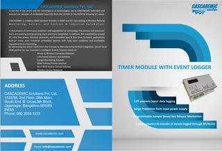
- 1. CASCADEMIC Solutions Pvt. Ltd. In the era of the smart and the convergence of technologies, we at CASCADEMIC extended and evolved our decades of embedded expertise from the SCADA to the M2M & Growing IoT space. CASCADEMIC is a Fabless ODM Solution Provider in M2M and IoT. Specializing in Wireless Remote M o n i t o r i n g , S e n s o r s , a n d C o n t r o l s & I n d u s t r i a l A u t o m a t i o n . In the process of continuous evolution and upgradation of technology, the process and processor SoC's are evolving and becoming more and more integrated. In addition, the complexities around RF, Ultra low power, Wireless protocols, and Embedded Java & Real time firmware applications built-on many such industrial embedded devices with long term reliability and availability requirements are increasing. By addressing the above needs from the Concept to Manufacturing Vertical Integration, we act as an ODM partner for our Customer's Intelligent System Solution needs of: Energy Monitoring Solution OEM Thermal Printer Solution Wi-Fi RFID Access Control Solution Wireless Sensor Networks Wired to Wireless Converter/Adatpter LoRa based solution and Gateway ADDRESS CASCADEMIC Solutions Pvt. Ltd. 1525/58, 2nd Floor, 28th Main, South End ‘B’ Cross,9th Block, Jayanagar, Bangalore-560069 INDIA Phone: 080 2658 3333 Email: info@cascademic.com www.cascademic.com TIMER MODULE WITH EVENT LOGGER 5 PF contacts input data logging Surge Protection from input power supply Programmable Jumper Based Key Release Mechanism Communication & transfer of events logged through BT/RS232
- 2. Features: Level Crossing Gate Timer Control Relay Room Monitoring Event Monitoring Application: Product Description: The level crossing gates at present are all manually operated. The negligence of rules from some gate men has been a cause of accidents. To prevent these accidents and negligence, some level of check has to be brought in the level crossing gates. There is a need for devices to be installed at the level crossing to provide a timer based release mechanism of the gate and data logging of the events in the LC Gate. Front End Processor - Inputs & Outputs Ÿ 5 channel input data logging in the system Ÿ Relay Based output Mechanism to Control the key Ÿ Two parallel relays Ÿ To take care of any redundancy features Ÿ Emergency Override Ÿ In case if this signal is activated, the circuit will revert to a FAIL- SAFE mode of operation. Ÿ Fail Safe mechanism to release the gate in case the relays fail to release the key Ÿ This event will get logged and send alerts. Ÿ This will be an external feature. Not related to the LC Gate Module. Ÿ LEDs Ÿ Showing the different modes of operation Ÿ Power Supply taken from the 24V DC power input line Ÿ The system will have to work with 12 Hours power backup Power Supply Ÿ Power Supply taken from the 24V DC power input line. Ÿ Surge Protection from input power supply. Ÿ Isolated Power supply. Ÿ Onboard battery – to take care of intermittent power failures. Data Transfer& Handheld Ÿ Data Communication and transfer of events logged to the external device through BLE Ÿ A suitable Handheld device with the associated software Ÿ The required data exchange will be through the BLE interface Ÿ To obtain the logged event data through the handheld device at time periods fixed by the customer. Ÿ RS232 interface, will be provided, as optional interface as an alternate provision. Data logger Ÿ To support totally 5 inputs Ÿ The analog data will be logged in steps of 0.5V Ÿ The data will be sampled at the occurrence of every event. Ÿ Data logger configuration through Bluetooth/Mobile/RS-232. Ÿ Mobile Number Configuration Ÿ PF contact configuration. Ÿ GateID configuration Ÿ Data back-up with built-in RTC (Real Time Clock) for storing the records Ÿ Based on time stamping. Ÿ The data will be stored in its onboard memory Ÿ For a minimum period of 3 months Ÿ The data will be stored on FIFO based approach. Ÿ Onboard battery – to take care of intermittent power failures Ÿ Up-to 2 days of event logging Time Delay Ÿ Programmable Jumper Based Key Release Mechanism Ÿ The delay duration can be selected from any one of the following 3 settings Ÿ 30 sec. Ÿ 60 sec. Ÿ 120 sec. Ÿ This will be selectable, through a 3 position switch. Ÿ This switch will be mounted inside the enclosure