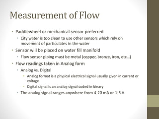
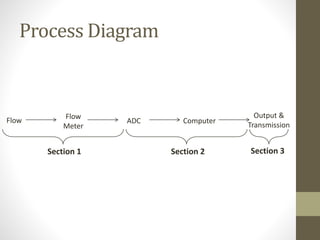
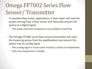
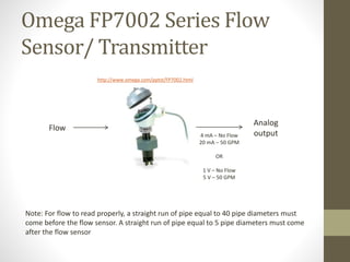
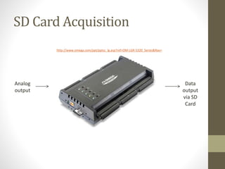
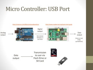
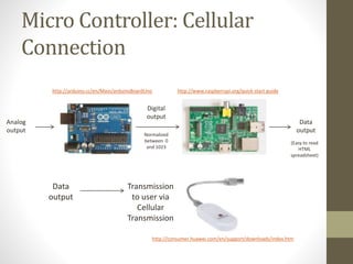
Flow Data
Acquisition
Nick Chapman
Michael Hays
December 2013 - January 2014
Purpose of Presentation
• This research project has allowed Greenscape to spend
minimal resources on finding a multitude of potential
solutions to the given problem. This presentation will provide
all the information that has been gained so that future parties
can learn, obtain and apply this knowledge
Identification of the Problem
• Greenscape needs to read, acquire, transmit, and manipulate
flow meter readings to further understand water losses in day-
to-day operations of any chosen water feature
Functional Requirements
• Measure flow readings
• Transmit data to Greenscape
• Data is easy to read and manipulate
• Overall solution is reliable and cost effective
Measurement of Flow
• Paddlewheel or mechanical sensor preferred
• City water is too clean to use other sensors which rely on
movement of particulates in the water
• Sensor will be placed on water fill manifold
• Flow sensor piping must be metal (copper, bronze, iron, etc…)
• Flow readings taken in Analog form
• Analog vs. Digital
• Analog format is a physical electrical signal usually given in current or
voltage
• Digital signal is an analog signal coded in binary
• The analog signal ranges anywhere from 4-20 mA or 1-5 V
Transmission of Data
• Wireless communication preferred
• Internet Communication
• Easy when internet connection is available
• However, using a client’s internet is most likely out of the question
• Cellular Communication
• Can be used in any application as long as there is a 3G (or better)
network connection
• RF Communication
• Limited range
• USB or SD card communication is “fall back” plan
• Simple to set up
• Works in all applications
• Requires labor force to retrieve data periodically
Data Manipulation
• Data must be easily read and analyzed by Greenscape
• A custom or purchased program designed to acquire and
analyze the given data may be used
• Companies may provide data logging software
• Data that is easily transferred into an existing program (such
as Microsoft Excel) may be used
Economics and Reliability
• System must be as cost effective as possible for production
purposes
• Data must be able to be sent 24 hours a day and 7 days a
week
• System cannot fail due to the vault environment
Potential Solutions
• Cellular data transmission using a paddlewheel flow
sensor/transmitter
• Use existing components already in production
• Use micro controllers to process and transmit data wirelessly
• SD card data acquisition using a paddlewheel flow
sensor/transmitter
• USB data acquisition using a paddlewheel flow
sensor/transmitter
• Use micro controller to process and transmit data to USB port
Flow Flow
Meter
ADC Computer
Output &
Transmission
Section 1 Section 2 Section 3
Process Diagram
Omega FP7002 Series Flow
Sensor/ Transmitter
• In standard flow meter applications, a flow meter will read the
pulses coming from a flow sensor and internally convert the
pulses to a digital signal
• This means that two components are needed to read flow
• The Omega FP7002 series flow sensor/transmitter will read
the incoming pulses from the paddlewheel and convert the
pulses into an analog signal
• This analog signal is much easier read by a variety of components
• Only one component is needed
Omega FP7002 Series Flow
Sensor/ Transmitter
Note: For flow to read properly, a straight run of pipe equal to 40 pipe diameters must
come before the flow sensor. A straight run of pipe equal to 5 pipe diameters must come
after the flow sensor
Flow
http://www.omega.com/pptst/FP7002.html
Analog
output
4 mA – No Flow
20 mA – 50 GPM
OR
1 V – No Flow
5 V – 50 GPM
SD Card Acquisition
• Using an Omega FP7002 series flow sensor, an analog signal may be
sent to an Omega OM-LGR -5320 series data logger
• After configuring the data logger with a PC, the logger uses it’s on-
board computer to log the data and store it on removable SD cards
• The SD cards will need to be pre-programmed via a computer that
has Omega’s DAQLog software installed
Flow Sensor:
• http://www.omega.com/pptst/FP7002.html
Data Logger:
• http://www.omega.com/pptst/OM-LGR-5320_Series.html
SD Card Acquisition
Analog
output
Data
output
via SD
Card
http://www.omega.com/ppt/pptsc_lg.asp?ref=OM-LGR-5320_Series&Nav=
Micro Controller: USB Port
• The data – preferably in easily-read format (HTML file) –
would be sent to a USB drive in the Raspberry Pi
• Collecting the data would be as simple as transferring a file
through the use of a USB drive
• Temporary solution that provides the data but doesn't give the
accessibility of a wireless data transmission
Micro Controller: USB Port
Analog
output
http://arduino.cc/en/Main/arduinoBoardUno
Digital
output
http://www.raspberrypi.org/quick-start-guide
Data
output
Normalized
between 0
and 1023
(Easy to read
HTML
spreadsheet)
Data
output
Transmission
to user via
Flash Drive or
SD Card
Micro Controller: Cellular
Connection
• USB modem would provide automatic access to live streaming
data via the World Wide Web
• May require a good amount of programming to allow the
constant updating
• This is the ultimate goal of the project – complete
independence from the work site
• Important – the USB modem must be Linux compatible to
work with the Raspberry Pi
• Huawei Cellular Modem:
http://consumer.huawei.com/en/support/downloads/index.htm
Micro Controller: Cellular
Connection
Analog
output
http://arduino.cc/en/Main/arduinoBoardUno
Digital
output
http://www.raspberrypi.org/quick-start-guide
Data
output
Normalized
between 0
and 1023
(Easy to read
HTML
spreadsheet)
Data
output
Transmission
to user via
Cellular
Transmission
http://consumer.huawei.com/en/support/downloads/index.htm
Micro Controller Program
• A simple program has been written that normalizes an analog
voltage signal into a number that ranges between 0 and1023
• A simple conversion factor can be calculated to change this
normalized value into a reading of flow (in GPM)
Overview of Installation
• Note: dielectric fittings will be needed to prevent galvanic
corrosion between the copper and galvanized iron
Copper piping (length equal
to 40 times pipe diameter)
Dielectric fitting
Galvanized Iron Tee
Flow Sensor/Transmitter
Analog output
Copper piping (length equal
to 5 times pipe diameter)
Removing the System
• Because the flow sensor is located on the fill manifold, extra
precaution will be needed
• Isolation valves will be needed on either side of the system for
maintenance and removal
• To remove the system, the piping on either side will be cut
• A length of copper pipe equal to the length of the overall system
will be put in it’s place
• “Repair” crimp bushings will be needed to crimp the piping in
place
Conclusion
• SD Card Data Transmission
• Available for immediate purchase and implementation
• Expensive: $1,900 (just including flow sensor and data logger)
• Requires periodic labor for data retrieval
• Professional data logger software provided
• Micro Processor: USB option
• Much cheaper than previous option: $550
• This includes the micro processor, computer and flow sensor
• Requires more programming
• Requires periodic labor for data retrieval
Conclusion
• Micro Processor: Wireless Option
• Requires more programming and research
• Does not require any periodic labor for data retrieval
• Comparable price to the USB option: $600

Flow Data Acquisition Presentation

  • 1.
    Flow Data Acquisition Nick Chapman MichaelHays December 2013 - January 2014
  • 2.
    Purpose of Presentation •This research project has allowed Greenscape to spend minimal resources on finding a multitude of potential solutions to the given problem. This presentation will provide all the information that has been gained so that future parties can learn, obtain and apply this knowledge
  • 3.
    Identification of theProblem • Greenscape needs to read, acquire, transmit, and manipulate flow meter readings to further understand water losses in day- to-day operations of any chosen water feature
  • 4.
    Functional Requirements • Measureflow readings • Transmit data to Greenscape • Data is easy to read and manipulate • Overall solution is reliable and cost effective
  • 5.
    Measurement of Flow •Paddlewheel or mechanical sensor preferred • City water is too clean to use other sensors which rely on movement of particulates in the water • Sensor will be placed on water fill manifold • Flow sensor piping must be metal (copper, bronze, iron, etc…) • Flow readings taken in Analog form • Analog vs. Digital • Analog format is a physical electrical signal usually given in current or voltage • Digital signal is an analog signal coded in binary • The analog signal ranges anywhere from 4-20 mA or 1-5 V
  • 6.
    Transmission of Data •Wireless communication preferred • Internet Communication • Easy when internet connection is available • However, using a client’s internet is most likely out of the question • Cellular Communication • Can be used in any application as long as there is a 3G (or better) network connection • RF Communication • Limited range • USB or SD card communication is “fall back” plan • Simple to set up • Works in all applications • Requires labor force to retrieve data periodically
  • 7.
    Data Manipulation • Datamust be easily read and analyzed by Greenscape • A custom or purchased program designed to acquire and analyze the given data may be used • Companies may provide data logging software • Data that is easily transferred into an existing program (such as Microsoft Excel) may be used
  • 8.
    Economics and Reliability •System must be as cost effective as possible for production purposes • Data must be able to be sent 24 hours a day and 7 days a week • System cannot fail due to the vault environment
  • 9.
    Potential Solutions • Cellulardata transmission using a paddlewheel flow sensor/transmitter • Use existing components already in production • Use micro controllers to process and transmit data wirelessly • SD card data acquisition using a paddlewheel flow sensor/transmitter • USB data acquisition using a paddlewheel flow sensor/transmitter • Use micro controller to process and transmit data to USB port
  • 10.
    Flow Flow Meter ADC Computer Output& Transmission Section 1 Section 2 Section 3 Process Diagram
  • 11.
    Omega FP7002 SeriesFlow Sensor/ Transmitter • In standard flow meter applications, a flow meter will read the pulses coming from a flow sensor and internally convert the pulses to a digital signal • This means that two components are needed to read flow • The Omega FP7002 series flow sensor/transmitter will read the incoming pulses from the paddlewheel and convert the pulses into an analog signal • This analog signal is much easier read by a variety of components • Only one component is needed
  • 12.
    Omega FP7002 SeriesFlow Sensor/ Transmitter Note: For flow to read properly, a straight run of pipe equal to 40 pipe diameters must come before the flow sensor. A straight run of pipe equal to 5 pipe diameters must come after the flow sensor Flow http://www.omega.com/pptst/FP7002.html Analog output 4 mA – No Flow 20 mA – 50 GPM OR 1 V – No Flow 5 V – 50 GPM
  • 13.
    SD Card Acquisition •Using an Omega FP7002 series flow sensor, an analog signal may be sent to an Omega OM-LGR -5320 series data logger • After configuring the data logger with a PC, the logger uses it’s on- board computer to log the data and store it on removable SD cards • The SD cards will need to be pre-programmed via a computer that has Omega’s DAQLog software installed Flow Sensor: • http://www.omega.com/pptst/FP7002.html Data Logger: • http://www.omega.com/pptst/OM-LGR-5320_Series.html
  • 14.
    SD Card Acquisition Analog output Data output viaSD Card http://www.omega.com/ppt/pptsc_lg.asp?ref=OM-LGR-5320_Series&Nav=
  • 15.
    Micro Controller: USBPort • The data – preferably in easily-read format (HTML file) – would be sent to a USB drive in the Raspberry Pi • Collecting the data would be as simple as transferring a file through the use of a USB drive • Temporary solution that provides the data but doesn't give the accessibility of a wireless data transmission
  • 16.
    Micro Controller: USBPort Analog output http://arduino.cc/en/Main/arduinoBoardUno Digital output http://www.raspberrypi.org/quick-start-guide Data output Normalized between 0 and 1023 (Easy to read HTML spreadsheet) Data output Transmission to user via Flash Drive or SD Card
  • 17.
    Micro Controller: Cellular Connection •USB modem would provide automatic access to live streaming data via the World Wide Web • May require a good amount of programming to allow the constant updating • This is the ultimate goal of the project – complete independence from the work site • Important – the USB modem must be Linux compatible to work with the Raspberry Pi • Huawei Cellular Modem: http://consumer.huawei.com/en/support/downloads/index.htm
  • 18.
    Micro Controller: Cellular Connection Analog output http://arduino.cc/en/Main/arduinoBoardUno Digital output http://www.raspberrypi.org/quick-start-guide Data output Normalized between0 and 1023 (Easy to read HTML spreadsheet) Data output Transmission to user via Cellular Transmission http://consumer.huawei.com/en/support/downloads/index.htm
  • 19.
    Micro Controller Program •A simple program has been written that normalizes an analog voltage signal into a number that ranges between 0 and1023 • A simple conversion factor can be calculated to change this normalized value into a reading of flow (in GPM)
  • 20.
    Overview of Installation •Note: dielectric fittings will be needed to prevent galvanic corrosion between the copper and galvanized iron Copper piping (length equal to 40 times pipe diameter) Dielectric fitting Galvanized Iron Tee Flow Sensor/Transmitter Analog output Copper piping (length equal to 5 times pipe diameter)
  • 21.
    Removing the System •Because the flow sensor is located on the fill manifold, extra precaution will be needed • Isolation valves will be needed on either side of the system for maintenance and removal • To remove the system, the piping on either side will be cut • A length of copper pipe equal to the length of the overall system will be put in it’s place • “Repair” crimp bushings will be needed to crimp the piping in place
  • 22.
    Conclusion • SD CardData Transmission • Available for immediate purchase and implementation • Expensive: $1,900 (just including flow sensor and data logger) • Requires periodic labor for data retrieval • Professional data logger software provided • Micro Processor: USB option • Much cheaper than previous option: $550 • This includes the micro processor, computer and flow sensor • Requires more programming • Requires periodic labor for data retrieval
  • 23.
    Conclusion • Micro Processor:Wireless Option • Requires more programming and research • Does not require any periodic labor for data retrieval • Comparable price to the USB option: $600