SlideShare a Scribd company logo
1 of 29
Download to read offline
Unit VI : Electron Optics Wankhede Madam
Unit IV - ELECTRON OPTICS
Basic Definitions:-
Electric field intensity/ strength :- Let a charge Q sets up an electric field in its surrounding space (area) . If
a charge q is placed at any point in the region around the charge Q, it experiences a force due to electric field
sets up by Q. “Thus, electric field strength/ intensity is defined as the force per unit charge at that point.”
E =
𝑭
𝒒
F = qE
F = q Q
4πєoєr r2
Since, E = = q Q
4πєoєr r2
Electric field is conventionally represented by lines of force. Field lines indicate the magnitude as well as
direction of the field. In uniform electric field, the field lines are straight, parallel and equally spaced shown in
fig. 1.
Field lines are curved and spaced non-uniformly in a non-uniform electric field shown in fig. 2.
+
+
Fig. 1 Fig. 2
Direction of electric field lines are always from positive potential to negative potential
Electric Potential(V):- When an electric charge is moved towards like charges or away from an unlike
charges then work is done against the force of attraction & repulsion by an external agency. Hence the electric
charge acquires the potential energy. If the charge is released work is done by the field.
Definition:- “The electric potential at a certain point P in the field E, is the work done to bring a unit positive
charges from infinity upto that point P against the electric lines of force.”
V = = = = Ed E = V / d
Electron Volt(eV):- It is the unit of measurement of energy. As the amount of kinetic energy acquired by
atomic particles is very small compared to Joule, so their energies are expressed in electron volts.
Definition:- It is defined as the energy acquired by an electron accelerated through a potential of one volt.
1eV = 1.602 x 10⁻¹⁹
J
CASE- I MOTION OF CHARGED PARTICLE IN UNIFORM LONGITUDINAL ELECTRIC FIELD
(i. e. v II E)
-
Unit VI : Electron Optics Wankhede Madam
Let A & B are two plane parallel metals plates of equal area, separated by distance ‘d’ and insulated
from each other. If a d.c voltage source s applied between two plates, then the plates are charged oppositely and
an electric field is produced in the region between the plates. The field lines are directed from +ve to –ve. If the
potential difference between A & B is V, then the electric field strength is given by
E = V / d ------(1)
Now assuming that it is a parallel plate capacitor, let an electron of mass ‘m’ and charge ‘e’ be placed at rest in
uniform electric field and then it is released. This electron experiences a force due to electric field
F = -eE ---------(2)
-ve sign indicates that the force accelerates the electron in a direction opposite to the direction of electric field.
Electron travels in a straight-line path opposite to the direction in which electric field is acting.
CASE II :- Motion of particle perpendicular to uniform electric field (i.e. v ⊥ E)
Consider an electron moving in a uniform perpendicular Electric field intensity E ⃗.
Let, d - distance between two parallel plates.
V - potential difference between two plates.
vo- initial velocity acquired by the electron moving in x- direction
VA- Accelerating Potential applied between cathode and anode inside Electron Gun.
The electron moves along a parabolic path in a transverse electric field.
Motion of an electron in a uniform magnetic field
A static magnetic field does not act on an electron which is at rest. However when electron moving with a
velocity v enters in a magnetic field, it experiences a magnetic force is given by
FL = e(v x B)
FL = evBsinθ -------(1)
The direction of the force FL is neither along the direction of v or that of B, but lies along the normal to
the plane containing both vectors v & B i.e., Lorentz force is always perpendicular to the displacement of the
electron.
The magnetic field does not produce any change in the speed or kinetic energy of an electron.
Kinetic energy of a charged particle remains constant when it moves in a uniform magnetic field. (S-
15/3m)
The magnetic field cannot change the speed ‘v’ and the kinetic energy of the electron.
CASE- I:- Longitudinal uniform magnetic field / magnetic field parallel to initial velocity
e
e-
B
Unit VI : Electron Optics Wankhede Madam
If an electron moves parallel to the magnetic field lines the, magnetic force (FL)on it is zero.
i.e. FL = evBsinθ = 0 (since, θ = 0 )
similarly, if the electron moves opposite to the field, the magnetic force on it will be zero.
i.e. FL = evBsinθ = 0 (since, θ = 180o
)
As the force is zero, the acceleration is zero. Therefore the electron continues to move along the initial
direction of motion without suffering any change in its speed or direction of motion.
CASE- II:- Transverse uniform magnetic field / magnetic field perpendicular to direction of electron
Let us now consider the case of an electron moving in a uniform magnetic field(B) with its initial
velocity(v) perpendicular to the field. Let θ be an angle between v & B which
is 90o
. thus the magnetic force is given by FL = evBsinθ
FL = evB --------(1) (since, θ = 90o
)
(it is assumed that the magnetic field in into the page and indicated by crosses). This force cannot change the
magnitude of electron velocity but deflects the electron continuously along a curvilinear path. The force FL
provides the centripetal acceleration which is necessary for the uniform circular motion of the electron. Thus FL
is a centripetal force acting on an electron.
According to Newton’s law of motion, the centripetal force is given by,
FC =
FL = FC
evB =
r = -----------(2)
r α mv (*This eqn
shows that the radius is directly proportional to the momentum)
Since all the parameters in eqn (2) are constant, thus r remains constant. Thus the locus of points at a constant
distance from a centre point is a circle. Therefore an electron describes a circular path in a plane
perpendicular to the magnetic field.
Q. What are the shapes or trajectories of an electron in electric and magnetic field when?
i) v parallel to E ---- straight line path
ii) v perpendicular to E ---- parabolic path
iii) v parallel to B ---- straight line path
iv) v perpendicular to B ---- circular path
Unit VI : Electron Optics Wankhede Madam
Electric and magnetic field in cross field configuration
Q.) What is crossed field configuration? Explain. Determine the velocity of the charged particle without
any deviation? (S-16/3m)
When uniform electric and magnetic fields are perpendicular to each other and act over the same region,
then they are said to be in crossed configuration.
Consider the pair of plane parallel metallic plates A & B which sets up the electric field acting vertically
downward. The magnetic field of induction B is applied perpendicular to the electric field and acting into the
page.
When an electron passes through the region along a direction normal to both the fields then it
experiences electric and magnetic field at the same time.
The electric field deflects the electrons upward whereas the magnetic field deflects the electrons in
downward direction.
The force due to the electric field is,
FE = eE
And the force due to the magnetic field is,
FL = evB
If the magnitudes of the fields E and B are adjusted such that the force exerted by these fields on
electron becomes equal to each other, hence the electron will not experience any force.
Thus,
FE = FL
eE = evB
v = E /B
This shows that electrons experience a zero net force as the two forces balance each other and they will not
deviate from their original straight line path and travel without change in the velocity v.
Velocity Filter
Q.) Explain the function of velocity filter. (S-13/3m)
Q.) Explain the working of velocity filter. (W-13/3m), (W-15/3m)
Q.) Explain the working of velocity selector with the help of necessary diagram (S-14/3m)
Q.) Explain the working of velocity selector (S-15/3m) (W-16/3m)
Q.) Explain why slower particles and faster particles require the same time for completing one rotation
in magnetic field. (S-14/3m)
The velocity filter is an electro-optic device, which uses uniform electric and magnetic fields in crossed
field configuration for selecting a stream of charged particles of single velocity from a beam of charged
particles having a wide range of velocities(𝐢. 𝐞. 𝐯 ± ∆𝐯).
The selection of the particles of same velocity is done by using crossed-field configuration.
Unit VI : Electron Optics Wankhede Madam
Working: As shown in Fig. consider a beam of electrons with different velocities 𝑣±𝑑𝑣 enters the crossed field configuration.
The electrons experience both electrostatic force FE due to the electric field and Lorentz’s force FL due to the presence of
magnetic field.
If the magnitude of the fields E and B are adjusted such that the electrostatic force balances the magnetic force, then
those electrons having velocity ‘𝑣’ will not experience any force and continue to travel in a straight path undeviated. Thus,
when FE = FL
qE = q𝑣B … … … … … … … (6.18)
∴ 𝑣 =
Fig. : Working of velocity filter
The electrons moving with the velocities other than ‘𝑣’ are deflected upward or downward along OP or OQ. For those electrons
which are moving with higher velocity (say 𝑣 = 𝑣 + 𝑑𝑣), 𝐹 > 𝐹 and they are deflected downward along OQ in circular
path. The electrons which are moving with lower velocity (say 𝑣 = 𝑣 − 𝑑𝑣), 𝐹 > 𝐹 hence they are deflected upward along
OP in parabolic path.
These electrons which are deflected sideways are absorbed by the slit walls. Thus, a strictly homogeneous single
velocity electron beam travelling along OR is obtained with the help of crossed fields. This arrangement is, therefore,
known as a velocity filter or velocity selector.
The arrangement is therefore known as velocity filter or velocity selector. The velocity filter is used in
Bainbridge Mass Spectrograph.
Numericals
1) An electron passes undeviated through velocity selector having E=104 V/m and B= 0.02T. Determine
the speed of electron. (W-14/2m)
Ans. v = E/B = 104
/0.02 = 50 x 104
m/s
2) An electron beam passes through magnetic field of 2x 10⁻³ Wb/m2 and electric field of 3.4x 10⁴V/m
both acting simultaneously at the same point. The path of the electron remains unchanged. Calculate the
electron speed. (S-13/3m)
Ans. B=2x 10⁻³
Wb/m2
, E=3.4x 10⁴
V/m
v = E/B = 3.4x10⁴
/2x 10-3
= 1.7 x 10⁷
m/s
Unit VI : Electron Optics Wankhede Madam
BETHE’S LAW (ELECTRON REFRACTION)
Q.) What is Bethe’s law? Discuss similarities and differences between Bethe’s law and
snell’s law. (S-13/3m)
Q.) Explain Bethe’s law. (W-13/3m)
Q.) Explain Bethe,s law with necessary diagram and state its similarities with snell’s law. (S-14/3m)
Q.) Explain Bethes law with the help of necessary diagram and discuss the similarities with snell’s law.
(W-14/4m)
Q.) What is Bethe’s law? Discuss the refraction of electron beam across the boundary separating two
equipotential regions. (S-15/4m)
Q.) Discuss the refraction of electron beam across an equipotential surface. (W-15/3m)
Q.) Explain Bethe’s law of electron refraction. (S-16/3m)
Q.) State the law that governs the reflection of electron. In what way it resembles the snell’s law and in
what way it differs from it. (W-16/3m)
A nonuniform electric field is a field in which electric intensity varies from point to point. In such a field
electric field lines are not straight and also not evenly spaced. On an equipotential surface, the electric potential
remains constant and the electric field lines are normal to the surface at any point. Therefore, the normal to the
equipotential surface shows the line of action of electric force on the electron.
When a narrow beam of electron travels in a non-uniform electric field, it bends and follows a curved path. This bending of
electrons by non-uniform electric fields is called as electron refraction.
Fig.6.: Refraction of electron beam in non-uniform electric field
Consider an equipotential surface AB. It is considered as the boundary across which the potential V1 abruptly
changes to potential V2. Let an electron travel through the region I with a uniform velocity v1 and enter in
region II. As the electron passes through the equipotential surface AB, it experiences a force which alters its
velocity. Because the electric field exists only in the vertical direction the y component of electron velocity
(normal component of electron velocity) vy undergoes a change whereas, , the X component of velocity
(tangential velocity component) vx remains constant. The resultant velocity v2 in region II is different
from v1.
If V2 > V1, vy increases or if V2 < V1, vy decreases. Here V2 > V1 hence vy increases. The electron path is
therefore bent nearer in the surface normal. The electron refraction that occurs at the equipotential surface is
Unit VI : Electron Optics Wankhede Madam
similar to the light refraction taking place at the boundary of rarer-to-denser medium. The equipotential
surfaces such as AB play the role of refracting boundary in case of charged particles.
As, the X component of velocity (tangential velocity component) remains constant in region-I and in region-II,
we write,
vx= vx’
v1 sinθ1 = v2 sinθ2
= ---------- (1)
using v= in eqn
(1)
we get, = [ ]1/2
This relation is known as the Bethe’s law for electron refraction
Explanation of Snell’s Law
When a light ray passes from rarer medium to denser medium, it bends toward the normal.
By snell’s law,
2
1
1
2
1
2
/
/
sin
sin
v
v
v
c
v
c
r
i





SIMILARITIES AND DIFFERENCES BETWEEN BETHE’S LAW AND SNELL’S LAW
SIMILARITIES
1) Both laws deal with the phenomenon of refraction.
2) When light ray travels from rarer to denser medium, it bends towards the normal. Similarly, electron beam bends towards the
normal when it travels from low potential to high potential region. Therefore, angle of refraction is less than angle of
incidence.
3) Velocity of light or that of electron beam changes after refraction.
4) Both light ray as well as electron beam follow the law of reversibility.
5) The ratio of refractive index of electrostatic fields is expressed in units of square root of volt.
DIFFERENCES
Table 1: Differences between Bethe’s Law and Snell’s Law
Unit VI : Electron Optics Wankhede Madam
S.No. BETHE’S LAW SNELL’S LAW
1. When the electron beam travels from a
region of lower potential to higher
potential, its velocity increases on
entering the region of higher potential.
When the light beam enters from rarer to
denser medium, its velocity decreases on
entering the denser medium
2. In terms of velocities, Bethe’s law
can be written as
θ
θ
=
In terms of velocities, Snell’s law can be
written as =
Hence the order of velocities is reversed.
3.
Bethe's law deals with refraction of
electron beam at the boundary
between two regions with different
potentials.
Snell’s law deals with refraction of light
beam at the boundary between two media
with different refractive indices.
Above fig. shows the motion of an electron in a nonuniform electric field represented by equipotential
surface separating equipotential regions of potential V1,V2,V3,V4 etc. At each surface electron path bends
towards or away from the higher or lower potential region. It is observed that the electron motion occurs
along a curved path in a non-uniform electric field.
Electrostatic lens (Electron lens):-
Principle:- When a stream of electrons travel through a non-uniform electric field it experience a change in
direction. So its path is bent at each equipotential surface in the same way as a light ray is bent at an optical
boundary (using optical terminology) .A stream of electrons may be called as an electron ray. Hence non-
uniform electric fields can be used to focus a bundle of electron rays just as a convex lens focuses light rays. A
non-uniform electric field produced by two coaxial metal tubes maintained at different potential can focus
electron rays and therefore, such a system is called as ‘electron lens’.
Construction:- An electron lens is made of two coaxial short cylindrical metal tubes T1 and T2 separated by
some distance. The tubes are held at different potentials V1 and V2 respectively. V2 and V1 a non-uniform
electric field is produced in the gap between the two tubes as shown figure. The equipotential surface are
perpendicular to the electric field the electric field within the hallow space of the tube is weak and negligible.
Unit VI : Electron Optics Wankhede Madam
Figure:-
Working :-
Let us consider a bundle of electron rays enters in the double cylinder lens system through the tube T1
which is held at a lower potential V1.
a) The electrons lablled as (1) move along the axis of the system, When it reached on the equipotential surface
in the gap they experience an electric force which acts along the axis in forward direction. Therefore, the
electrons gets accelerated towards tube T2 along axis without any deviation from their initial path of travel.
b) The electrons lablled (2) on reaching the equipotential surface in the gap experience an electric force which
acts at an angle to the direction of their motion. The force F experienced by electrons at the converse
equipotential surface can be resolved into rectangular components FII and FI. FII = act parallel to the axis while
FI= acts perpendicular to the axis.
Due to the force F1, the electrons are deflected down towards the axis and because of FII electrons accelerated
towards the T2.
c) Similarly, the electrons lablled (3), are deflected up towards the axis and also accelerated forward, thus all
off- the axis electron paths around the axis tends to converge towards the axis.
However, on crossing the midplane MM’ of the gap, the converging electron rays encounter equipotential
surface of concave shape.
In the second –half of the gap, the normal components of electric force, F┴ is directed always from the axis for
all off –axis as shown fig. and the Fǁ components is directed forward. As a result the electrons are accelerated
forward but tend to diverge.
Thus the first half of the gap acts like a convex lens where the electrons rays tends to converge and the second
half acts like a concave which defocuses the rays.
Unit VI : Electron Optics Wankhede Madam
For every set of values of V1 and V2 the conveying action will be stronger than the diverging action. Because
the electrons move slower in the lower potential region, they spend a larger in the first half of the gap and the
impulse ‘F11 t’ is greater for the convergence interval.
In the second half the electron move faster because of higher potential and the impulse ‘F11 t’ is smaller for
divergence interval.
Because of this action, the net result is that electron rays get focused. This double cylinder arrangement is
called an electrostatic lens or electron lens.
Comparison with the glass lens:-
1) Light rays are bent only at the two boundaries of a lens but electron rays are refracted continuously
through successive equipotential surface.
2) The focal length of a glass lens is fixed, whereas the focal length of an electron lens may be varied by
adjusting the potential V1 and V2 on the cylinders.
Applications:-
1) Electron lens is the most important components of an electron gun used for producing a narrow intense
electron beam.
2) Electron lens action is utilized in particle accelerates to focus charged particles into a narrow beam.
CRO
Q. Draw a schematic of Cathode Ray Tube and show its principle parts. Briefly
describe their function. W-01(6m), W-11(3m)
OR Draw the schematic of electrostatic CRT. Describe the role of
(i) Electron gun
(ii) Deflection system
(iii) Fluorescent screen
(iv) Aquadag coating S-07(5m)
OR Which voltage controls the intensity of electron beam on the screen in CRT?
What is the function of voltage given to the anode cylinders in it? S-09(3m)
OR What is the use of aquadag coating in CRT? S-09(2m)
OR Give the functions of each block of the CRO. W-02(2m), W-05(5m)
OR State the functions of different blocks of CRO. S-08(3m), W-09(5m)
OR Explain how the true shape of a voltage waveform is displayed on a CRO
screen. (5m)
OR Explain in brief the function of the time base circuit. W-06(4m), S-10(2m),
S-12(3m)
OR Explain the use of time base circuit in a CRO. W-07(5m)
OR Explain how the actual waveform of the signal is traced on the CRO screen
with the help of time-base generator. W-01(5m), S-05(3m)
OR How is CRO used to display A.C. waveform? W-08(3m)
OR Explain the necessity of time base circuit in the CRO. S-03(3m)
OR Is it possible to display the waveform on the CRO screen without the time
base generator. Explain. W-10(3m)
Q.) Draw block diagram of CRO and explain how intensity of trace is controlled on screen. (S-13/4m)
Q.) Explain the function of Aquadag coating on the screen of CRT. (S-13/2m)
Q.) Draw block diagram of CRO. Explain function of time base generator. (W-13/4m)
Unit VI : Electron Optics Wankhede Madam
Q.) Draw neat and clean diagram of Cathode ray oscilloscope. Explain function of time base generator
in brief. (S-14/4m)
Q.) Draw schematic diagram of CRO and explain the role of aquadag coating in CRT. (W-14/3m)
Q.) Draw block diagram of Cathode ray oscilloscope. (S-15/4m)
Q) Draw block diagram of CRO. How can intensity and focusing of the trace on the screen can be
controlled. (W-16/5m)
Q.) Describe the role of Aquadag coating in Cathode ray tube. (S-15/2m)
Q) Explain the role of acquadag coating in cathode ray tube. (W-16/2m)
Q.) Draw block diagram of CRO. Explain the role of electron gun. (W-15/3m)
Q. Draw the schematic of an electrostatic CRT, write the function of
(i)Electron gun and (ii) Aquadag coating (S-16/2+2m)
Block diagram of CRO
CRO is a very important electronic measuring instrument. It is used to display and measure electrical
signals, time interval, phase shift between two electrical signals, voltage and frequency of electrical
signals.
Basically CRO consists of seven major blocks
a) Cathode ray tube
b) Time base circuit
c) Trigger circuit
d) Vertical circuit
e) Horizontal circuit
f) High voltage power supply
g) Low voltage power supply
Unit VI : Electron Optics Wankhede Madam
Working of various blocks:
I) CRT: A cathode ray tube is a specially constructed vacuum tube in which an electron beam is controlled by
electric and magnetic field which generated a visual display of input electrical signals on fluorescent screen.It
consists of three main parts electron gun, deflection system and fluorescent screen.
The CRT is like a conical flask, placed horizontally and sealed at its one end. The electron gun contains several
electrodes mounted at one end of the tube. All electrodes are connected by using basepins. The deflection
system consists of two pairs of parallel metal plates. These plates are oriented in such a way that the orientation
is perpendicular to the axis of the CRT.
The screen consists of a thin coating of phosphors deposited on the surface of curve of envelope. The inner
surface of two side ends contains coating of graphite material which is known as acquadag coating.
a) Electron gun: An electron gun is a device which is used to produce a narrow electron beam of high
intensity.
Principle: It is based on the principle of non uniform electric field that cause bending of electronic paths.
Construction: the electron gun consists of a cathode (K), a filament heater (F), control grid (G) and three
anodes A1, A2 and A3.
The cathode K is a short hollow cylinder made up of nickel. The front face of cathode is coated with thoriated
tungsten or barium and strontium oxide that helps for thermionic emission to occur at moderate temperature
700o to 900oC. The cathode surrounded by the control grid having a small opening in its front face to pass the
electrons. Anode A1, A2 and A3 are coaxially situated beyond the cathode.
Working:
When power is switched on, the filament heats up the cathode. The electrons are emitted from the cathode and
pass through the control grid. The control grid is held at negative potential. When the grid is at less negative
potential then more number of electrons pass through it and intensity of the luminous spot on the screen is high.
Similarly, when the grid is held at high negative potential then less number of electrons pass through it and
intensity of the luminous spot on the screen is less. Thus, the grid acts as a gate and regulates the passage of
electrons through it. Thus control grid is used to control the intensity of the luminous spot on the screen.
Anode A1 accelerates the beam of electrons. The grid G and A2 forms the first lens which is used to
prefocusses the electron beam and known as prefocussing lens. A2 and A3 forms the second lens which
focuses the electron beam and convert it into s fine spot which is seen on the screen.
b) Deflection System: After emerging from the electron gun, a narrow and accelerated electron beam passes
toward the fluorescent screen, but before striking, theses beam passes through the deflection system. The
deflection system consists of two pairs of metals plates, aligned parallel to each other. These two pairs are
perpendicular to each other and also to the axis of CRT.
When a potential difference is applied to the horizontal plate, a uniform electric field is produced in
vertical direction. This plate causes a vertical deflection and hence the set of deflection plates are called vertical
deflection plates (VDP) also called Y-plates.
Unit VI : Electron Optics Wankhede Madam
Similarly, when potential difference is applied to the vertical plate, the uniform electric field is produced
horizontally and causes a horizontal deflection of the beam, hence the set of plates are called horizontal
deflection plates (HDP) and are called X-plates.
1) When voltages are not applied to X and Y plates, the electron beam travels straight and strikes on
the screen producing a bright spot at the centre.
2) When dc voltage is applied to Y plate in such a way that upper plate is at positive potential and
lower plate is at negative potential then electron beam is attracted toward upper plate and the spot
moves upward.
3) When lower plate is made positive and upper plate is negative then bright spot will move downward
on the screen.
Unit VI : Electron Optics Wankhede Madam
4) When a dc voltage is applied to X-plate in such a way that left plate is +ve and right plate is –ve
then spot moves toward left plate.
5) When left plate is –ve and right plate is +ve, the spot moves toward right plate.
6) When dc voltages are applied to both X and Y plates, the electron beam gets deflected along the
directions of their resultant.
Unit VI : Electron Optics Wankhede Madam
c) Fluorescent Screen: The interior surface of circular front face is coated with thin layer of phosphor.
The spot on the screen continues to glow for a short period of time even after the electron beam moves
away. This coating is made thin to allow thw light to pass through the screen and viewed from outside
the CRT.
Aquadag Coating :
1) When electrons strikes the screen, they tends to charge the screen negatively and repels the electrons arriving
afterwards. It will reduce the number of electrons reaching the screen and also the brightness of the glow.
2) Similarly, as electrons emitted from the cathode are in large number, the cathode assumes gradually a +ve
charge and again intensity of the glow on the screen reduces. Hence the cathode is to be replenished with
electrons. The acquadag coating is the conducting coating of aqueous solution of graphite which is used
to complete the electrical circuit from screen to cathode. The electrons striking the fluorescent screen not
only cause emission of light but produces secondary emission of electrons. The secondary electrons are
attracted by the anode A3 and the electrons are returned to cathode through the ground.
Note:
When ac signal voltage is applied to the Y plate the beam moves up and down along vertical line in steps with
varying voltages. The successive position of the spot cannot be displayed when signal frequencies are greater
than 20Hz. The phosphor continue to glow for a short time after the electron beam passes, due to persistence of
vision and the path of the beam across the screen is seen as a vertical line. It is called trace, the length of the
trace corresponds to the peak to peak voltage Vp-p of the applied signal.
Similarly horizontal motion of the electron beam is produced when an ac voltage is applied to X-plate.
II) Vertical circuit: the signal is applied to Y input. It goes through ac-dc-gnd switch. When the switch is set in
ac position then a capacitor is in series with the switch which allows ac signals to pass and blocks the dc
components. When the switch is set in dc, the signals is directly coupled. When the switch is set in gnd, the
signal containing ac and dc components is isolated and hence no deflection is obtained on the screen.
The signal amplitude can be increased or decreased to obtain an adequate deflection on the screen by the
volt/cm control (to get proper deflection on the screen).
III) Horizontal circuit: The voltage to X plate can be applied form internal source or external source. When
the switch is kept in external mode, the X plates are disconnected from the internal source. A signal connected
to X input passes to the X plate through an attenuator, preamplifier and horizontal amplifier. The output of
horizontal amplifier is fed to X plate. When the switch is kept in INT position a ramp voltage produced by an
internal time base circuit is applied to the horizontal amplifier.
Unit VI : Electron Optics Wankhede Madam
IV) Low voltage power supply: Low voltage power supply provides power to all the electronic circuits such
as trigger circuit, time base generator etc. it gives an output of the order of 400V.
V) High voltage power supply: The high voltage power supply provides power to circuit i.e. the electrodes in
the electron gun. It supplies voltage of the order of 1600 to 2200 volts.
VI) Time base circuit: It consists of time base generator. In the signal the voltage varies as a function of time
which requires the beam to move horizontally that covers equal distances in equal interval of time.
1) When the voltage is applied to X plate it rises through equal amount of voltage per unit time.
2) Secondly at the end of horizontal motion, the beam should return to the starting point after completing one
rotation, which is known as ramp voltage.
“ Ramp voltage is the voltage varies linearly with time.”
The time base generator is a variable frequency oscillator that produces an output voltage of sawtooth
shape known as sawtooth voltage.
[If a harmonic voltage is applied to X plates, voltage is applied to X plates, the voltage varies through different
amount in equal interval of time.]
 Time base generator is a variable frequency oscillator that produces time base voltage/ or
sweep voltage. This voltage is fed internally to X-plates of CRT to produce true shape of the
signal on the screen of CRO.
 True shape of the input signal voltage cannot be observed through vertical motion of the
beam.
 It can be displayed on the screen only if the beam is made to move simultaneously in a
horizontal direction by equal distances in equal interval of time. This is done by Time base
circuit.
 The sweep voltage starts from some initial value (V)-max
, increases linearly with time to
(V)+max
. This time is known as sweep time ts,
as it is sweeping from negative to positive
maxima, then it suddenly returns to its value (V)-max
again, this time is known as retrace time
tr
.
 The time taken by the electron beam to start from (V)-max and reach (V)+maxis called sweep time ts.
 The time taken by the electron beam to drop from (V)+max to (V)-maxis called retrace time or fly
back time tr.
 The sum of sweep time (ts) and retrace time (tr) is called sweep period (TS).
TS = ts + tr
Unit VI : Electron Optics Wankhede Madam
At t = 0, the ramp voltage is at its –ve max on the RHDP, the voltage rises uniformly with time
and the beam moves towards the right side on the screen. When ramp voltage reaches to zero, the
beam will come to the centre and when voltage increases the beam continues to move toward right end
of the screen. When the voltage drops instantaneously to a minimum value the spot is whipped (sweep)
back across the screen to its starting point on left edge from where it repeat the next cycle. Hence ramp
voltage is also called as sweep voltage or sawtooth voltage.
X-axis of the screen not only denotes amount of horizontal deflection but also the time covered
therefore it is called time base voltage.
The time taken by the sweep voltage to rise from its maximum negative voltage to its maximum
+ve voltage is known as sweep time or trace time (ts). the time taken by the sweep voltage to dip from
its positive maximum to negative maximum value is called fly-back time or retrace time (tr).
T sweep = ts + tr = ts
Q) Why ramp voltage is necessary? OR What are the conditions that must be fulfilled by the
horizontal voltage in order to trace the true wave shape of signal on the CRO screen?
CRO is used to measure the signal as a function of time. Signal which is to be tested is applied to y-
input of CRO. If ac signal voltage is given to y-plates, it makes the electron beam to move up and
down along vertical line so to reproduce faithful display of wave shape of signal on CRO screen it is
essential.
1) To spread the deflected electron beam horizontal through equal distances in equal interval of
time and
2) After completing one cycle, the beam should return to the starting point to repeat the next
motion (cycle).
The ramp voltage fulfils both these condition.
Q) What is Blanking? How is it achieved?
Blanking is the method of making retrace path of electron beam invisible during flyback time. Retrace
path can be made invisible by applying a high negative voltage pulse to the control grid in electron
gun which turns off electron beam momentarily.
Display of true shape of signal
 As the signal is applied to Y-plates and sweep voltage to the X-plates, the electron beam is
subjected to two forces acting in perpendicular direction to each other.
Unit VI : Electron Optics Wankhede Madam
 The deflection of the beam at any instant occurs along the direction of the resultant of the two
forces.
 As time progresses, the resultant change in magnitude and direction and the beam displays the
actual shape of the signal on the screen.
Q) What is synchronization ? How it is achieved in a CRO? S-11(3m)
OR Mention the function of a trigger circuit. S-01, 10(2m)
Q.) What are Lissajous patterns? Define synchronization. How the intensity of the trace on the screen is
controlled? (S-16/1+1+1m)
Q.) What is synchronization? (S-14/2m)
To get the steady and stable wave pattern on the CRO screen, horizontal deflection of electron beam
should start at the same point of the input signal in each sweep cycle. When it occurs it is said that
horizontal sweep voltage is synchronized with input signal.
“Synchronization is the method of locking of frequencies of both time base generator (x plate) to the
frequency of the input signal (y plate)”, to get a stationary display of wave pattern on CRO screen.
Signal is synchronized only when the following conditions are satisfied.
Fsignal = nfsweep
1/Tsignal = n(1/Tsweep)
Tsweep = n Tsignal
Eg. 1. If signal frequency is 50Hz and sweep frequency is 50Hz
Fsignal = nfsweep
50 = n 50
n = 1
Tsweep = Tsignal
Eg. 2. If signal frequency is 100Hz and sweep frequency is 50Hz
Fsignal = nfsweep
100 = n 50
n = 2
Unit VI : Electron Optics Wankhede Madam
Tsweep = 2 Tsignal
VII) Trigger Circuit: Synchronization of sweep and input signal voltage can be achieved by
triggering method. The role of trigger circuit is to make ensure that the horizontal sweep begins
at its specific time in the period of the vertical input signal.
Trigger Circuit produces trigger pulse which triggers the time base circuit to produce time base
voltage.It Synchronizes sweep voltage and input signal voltage.
Synchronization is the method of locking of frequency of time base generator (x- plate) with the
frequency of the input signal (y- plate) to get a stationary display of wave pattern on CRO screen”.
i.e., 𝒇𝒔𝒊𝒈𝒏𝒂𝒍=𝒏𝒇𝒔𝒘𝒆𝒆𝒑
or
𝑻𝒔𝒘𝒆𝒆𝒑=𝒏𝑻𝒔𝒊𝒈𝒏𝒂𝒍
To achieve the condition of Synchronization, a portion of input signal is fed to the trigger circuit of the
time base circuit
Q) What is function of delay line?
During the generation of trigger pulse, ramp voltage, the input signal is being fed through a delay line
that delays the input signal before it is further amplified and fed to y-plates. So delay line gives enough
time for developing trigger and the starting of ramp voltage.
Q. Explain how intensity and sharpness of the trace on the screen are controlled.
W-04(3m), S-11(2m), W-11(3m)
Ans. Intensity control:
The intensity of the display depends on the number of electrons striking the screen. Grid voltage regulates the
number of electrons coming out of the aperture and hence grid voltage regulates the intensity of the display.
When the grid is at less negative potential then more number of electrons pass through it and intensity
of the luminous spot on the screen is high. Similarly when the grid is held at high negative potential
then less number of electrons pass through it and intensity of the luminous spot on the screen is less.
Thus the grid acts as a gate and regulates the passage of electrons through it. Thus control grid is
used to control the intensity of the luminous spot on the screen.
Sharpness/ Focussing control: The three anodes A1, A2 and A3 are kept at different potentials from the
electrostatic lens which focuses the beam to a single spot on the screen. Hence, the potential on these anodes,
controls the sharpness of the display on the screen.
Applications of CRO
Unit VI : Electron Optics Wankhede Madam
CRO is used to measure variety of electrical parameters, some of quantities measured with its help are
described as follows.
1) Study of waveform: The signal under study is applied at the y-input terminal and the sweep
voltage is internally applied to x-plates. The waveform of the signal is displayed on the screen.
2) Measurement of dc-voltages: Initially the trace is adjusted to the center of the screen. The dc-
voltages under study is applied at y-input. The trace gets deflected upward or downward
depending upon the polarity of the applied voltage. The deflection is read on the graticule and
by multiplying it with deflection factor (volt/cm), the magnitude of the unknown voltage is
obtained.
Displacement = 1cm
Position of vertical amplifier = 1V/div
Applied voltage = 1x1 = 1V
3) Measurement of ac-voltages: The trace is adjusted at the centre of the screen and ac-voltage
under study is applied to y-input. The peak distance is measured and on multiplying it by
deflection factor Vp-p is obtained. The values of Vrms & Vavg are then calculated by using
formulae.
Vp = and Vrms =
√
= 0.707 Vp
Vavg = 0.636 Vp
4) Measurement of frequency: Method I: A sinusoidal signal whose frequency is to be
determined is applied to y-input. The time base control is adjusted to obtained 2 or 3 cycles of
the signal on screen. The horizontal spread of one cycle is noted. By multiplying it with time-
base sensitivity, the time period of the signal is obtained. Then the reciprocal of the time period
gives the frequency of the signal.
T = (horizontal spread of 1 cycle) x (position of time-base sensitivity)
F = 1/T
Unit VI : Electron Optics Wankhede Madam

 Time base sensitivity (x) =2 ms/cm
 Spread of wave (l) = 5.6 cm
 Time period T = 2x5.6 =11.2 ms
 Frequency f = 1/T
= 1/11.2ms
= 1000/11.2
= 89.28Hz.
5) Alternative method using Lissajou’s pattern: frequency of test signal can be measured using
lissajou’s pattern. When two sine waves oscillating in mutually perpendicular planes are
combined, different types of closed loop patterns are obtained. They are called as lissajou’s
pattern. If two sine waves of different frequencies are applied to x & y plates of a CRO then
closed loop pattern are displayed on the screen. A stable pattern is obtained when ratio of the
frequencies is an integer.
The number of points at which the loops are touching the horizontal and the vertical
tangents i.e. LH and LV are noted.
The unknown frequency is given by
𝑭𝒀 =
𝑳𝑯
𝑳𝑽
𝑭𝑿
Unit VI : Electron Optics Wankhede Madam
Eg. When two voltages are applied to x & y plates and ratio of frequency 2:1 (fig. g)
i.e. =
let the known and unknown signal source are connected to x & y plates respectively, by varying
frequency of the known source a stable loop pattern is displayed.
6) Measurement of phase difference or phase angle: when two sine waves oscillating in
mutually perpendicular planes are of the same frequency, the lissajou’s pattern takes the form of
an ellipse. The phase angle Ø can be calculated by using formula Ø = sin-1
(
′
′
)
BAINBRIDGE MASS SPECTROGRAPH
Unit VI : Electron Optics Wankhede Madam
Q.) Explain construction and working of Bainbridge Mass spectrograph. (W-13/5m)(W-15/4m) (S-16/3m)
Q.)Describe the working principle of a Bainbridge mass spectrograph with neat sketch. (S-13/5m)
Q.) Discuss the construction and working of velocity selector to produce the mono-velocity beam of
charged particle. (W-14/3m)
It is an instrument which, by using electric field and magnetic fields, separates isotopes from a stream of
positive ions of an element and measures their individual masses. This instrument separates ions of
different masses, hence called a mass spectrograph. It was designed by K. T. Bainbridge in 1933.
Principle:
Bainbridge mass spectrograph is based on the principle that a uniform magnetic field acting normal to the path
of ions having the same velocity deflects the ions of different masses along several circular paths of different
radii. The radius of each circular path is linearly related to the mass of the ion. Velocity selector is used to
produce monovelocity ion beam.
Construction:
It mainly consist of 1) Velocity selector 2) Analysing chamber or momentum selector. Bainbridge mass
spectrograph is vacuum chamber placed in a uniform magnetic field, acting perpendicular to its larger surface.
Positive ions of variable speed coming from ion-source are collimated by the slits S1 and S2. Deflection plates P
and Q are placed next to the slits. These are charged and produce electric field. Electric field and transverse
magnetic fields constitute a velocity selector/ filter. Slits S3 is arranged to collimate the narrow monovelocity
ion beam and allows it to pass through the analyzing chamber. A photographic plate is mounted in the
analyzing chamber in line with slit S3.
Working:
Unit VI : Electron Optics Wankhede Madam
An element under study is taken in the form of gas. The gas is ionized when the potential difference across the
electrodes. Positive ions are accelerated and conducted into the mass spectrograph through the slits S1 and S2.
These ions are of variable speed/velocity and of variable mass. They pass through the velocity filter, after
collimation through S1 and S2. The electric field strength is adjusted such that ions having a velocity v = E/B
merge out of the filter without deflection and pass through the slits S3. (ions having a velocity v=E/B i.e. FE =
FL for ions). Ions having velocities different form v get deflected away and are absorbed by the walls of the
chamber. Monovelocity ions after passing through the slit S3 enter the transverse uniform magnetic field B. this
transverse field B deflect these ions in a circular path. Monovelocity ions having same values get focused at the
same point on the photographic plates mounted in line with field acting on the chamber constitutes a
momentum selector and separates out ions of different masses. Different isotopes produce multiple vertical
lines.
The visual record of ions in the form of vertical lines on the photographic plates is called mass-
spectrum.
Q. Show that mass-scale is linear in Bainbridge mass-spectrograph?
Ans. Isotopes positions are recorded as vertical lines on photographic plates held in the analyzing chamber of
Bainbridge mass spectrograph. The distance of any line is measured from the centre of the slit S3 through which
the isotopes enter the evacuated analyzing chamber. Let ‘x’ be the distance of a line marked by a singly ionized
ion of mass M with velocity v, ‘R’ be the radius of its circular path.
X = 2R = diameter of circular path of ion
X = 2( ) (since v = E/B)
X = ----------(1)
∴ M = --------(2)
⇒ M α x -----------(3) (since is constant for given E & B)
Eqn
(3) is the equation of straight line. Thus mass scale is linear.
Derivation of line separation:
Let M1 and M2 be the masses of two isotopes and if x1 and x2 respectively are the distance from the centre of
the slit S3, then by using equation (1)
x1 = , x2 =
The line separation is given by,
Δx = (x2-x1) = (M2-M1)
Unit VI : Electron Optics Wankhede Madam
. LIST OF FORMULAE
MAGNETIC FIELD:
TRANSVERSE MAGNETIC FIELD:
 Lorentz force𝐹 = q (𝑣
⃗ × 𝐵
⃗) = q v B sin𝜃 = qvB when 𝑣
⃗ is perpendicular to 𝐵
⃗
for electron, 𝐹 = e(𝑣
⃗ × 𝐵
⃗) = evBsin𝜃 = evB
 Radius R of circular path =
for electron, R of circular path =
CROSSED ELECTRIC AND MAGNETIC FIELD CONFIGURATION
 F E = F L
 𝑣 =
BETHE LAW OF ELECTRON REFRACTION
 Bethe’s law in terms of potential =
 Bethe’s law in terms of velocity of an electron
Sin
Sin
=
BAINBRIDGEMASS SPECTROGRAPH
 The line separation between the isotopic masses (𝑥 − 𝑥 ) = (𝑀 − 𝑀 )
 To find unknown mass of an element (𝑀 − 𝑀 ) = (𝑥 − 𝑥 )
SOLVED NUMERICALS
1. An electron beam passes through a magnetic field 2×10⁻³
Wb/m2
and an electric field of 3.4×10⁴
V/m, both fields
being normal to each other and acting simultaneously in the same region. The path of electrons remains unchanged.
Calculate the electron speed? (3M)[Summer-13&17]
Ans. Given: B = 2×10⁻³Wb/m2,
E = 3.4×10⁴V/m
Solution: 𝑣 =
=
.
= 1.7 × 10 m/s
2. Determine the velocity of ions that pass undeflected through crossed E and B fields for which E=7.7 kV/m and
B=0.14T. (3M)[Winter-17]
Ans. Given: B = 0.14T,
E = 7.7kV/m= 7.7×10³
V/m
Solution: 𝑣 =
=
.
.
= 5.5 × 10 m/s
3. An electron passes undeviated through a velocity selector having E=104V/m and B=0.02T. Determine the speed of
electron. (2M)[Winter-09,14& 19]
Ans. Given: B = 0.02T,
E = 104
V/m
Solution: 𝐯 =
Unit VI : Electron Optics Wankhede Madam
= .
= 50 × 10 m/s
4. A positive ion beam moving along the x-axis enters a region of uniform electric field of 3kV/m along Y-axis and
magnetic field of 1 KG along z-axis. Calculate the speed of those ions, which pass undeviated. What will happen to
ions, which are moving (i) Faster, (ii) slower than these ions? (4M)[Winter-00 &02]
Ans. Given: B = 1KG = 103 G = 103×10-4Wb/m2 = 0.1T,
E= 3kV/m = 3×10³V/m
Solution: Speed 𝑣 =
=
.
= 3 × 10 m/s -------- for un-deviated ions.
Ions moving faster than these ions will be deflected towards magnetic field along circular path and slower ions will be
deflected towards electric field along parabolic path. Both deviated ions will be absorbed by slit walls of velocity
filter.
5.Electrons accelerated under a potential of 250V enters the electric field at an angle of incidence of 500 and gets
refracted through an angle of 300. Find the potential of second region. Find the potential difference between the two.
Ans. Given: V1=250V
θ1=500
θ2=300
V2=?
Solution:
θ
θ
=
Sinθ
Sinθ
=
V
250
⇒ V = 586.8V
∴ Potential difference = V − V = 586.8 − 250 = 336.8V
5. An electron beam enters from a region of potential 75 V into a region of potential 100V, making an angle of 450
with
the direction of electric filed. Find the angle through which the beam refracts. (3M)[Summer-
13](3M)[Winter-19]
Ans: Given: V1=75V
θ1=450
V2=100V
θ2=?
Solution:
θ
θ
=
⇒
Sin 45
Sin θ
=
100
75
Sin θ
Sin 45
=
75
100
Sin θ
= Sin 45
75
100
⇒ θ = 38°
a.
6. A. In a Bainbridge mass spectrograph, singly ionized atoms of Ne20passes into deflection chamber with velocity of
105 m/sec. if they are deflected by a magnetic field of flux density of 8 x 10⁻² Wb/m2, Calculate radius of the path of
singly ionized Ne20atom.
Ans: Given: v=105 m/sec
B=8 × 10⁻² Wb/m2
Unit VI : Electron Optics Wankhede Madam
M=20 a.m.u. = 20 ×1.67x10-27
Kg
q=1.602 × 10⁻¹⁹C
r=?
Solution:r =
r =
20 × 1.67 × 10 × 10
1.602 × 10 × 8 × 10
= 0.26m = 26cm.
Q.6.B. In a Bainbridge mass spectrograph, singly ionized atom of Ne20
passes into deflection chamber with the
velocity 103
m/sec. If they are deflected by a magnetic field of flux density 0.07Wb/m2
.Calculate the radius of path
of singly ionized Ne20
atom.
(3)S-18
Ans. Given: B= 0.07 wb/m2
v= 103
m/sec
M= 20 amu= 20 x 1.67 x 10-27
kg = 3.34X10⁻²⁶
kg, q = 1.602 x 10⁻¹⁹
C, R=?
Solution: 𝑅 = =
.
. .
= 2.978 x10⁻³
m
7. The electric field between the plates of a velocity selector is 150V/cm and the magnetic field common to both the
velocity selector and the analyzing chamber is 0.5T. If the source contains two isotopes of magnesium Mg 24,Mg25
which are single charged, then find the distance between the lines formed by these isotopes on photographic plate.
(4M)[Winter-15&16]
Ans: Given:E=150 V/cm= 150×102 V/cm
B=0.5T
M1=24×1.67×10-27Kg
M2=25×1.67×10-27Kg
q =1.602×10⁻¹⁹
C
∆x=?
Solution:
Δx =
2E(M − M )
B q
Δx =
× × ( )×1.67X10⁻²⁷
( . ) ×1.602x 10-19 = 1.245 mm
8. A. In a Bainbridge mass spectrograph, the electric field used is 8 x 10¹⁴ V/m ,the magnetic field common to both
places is 0.2 Wb/m2. If the ion source consists of singly ionized neon isotopes of atomic masses 20 and 22, calculate
linear separation of lines formed on photographic plate. (3M)[Summer-19,Winter-13]
Ans. Given: E=8 × 10¹⁴ V/m
B=0.2 Wb/m2
M1=20 ×1.67 x10-27Kg
M2=22 ×1.67 x10-27Kg
q =1.609 × 10⁻¹⁹C
∆x=?
Solution:𝛥𝑥 =
( )
=
× × ×( )×1.67X10⁻²⁷
( . ) ×1.609x 10⁻¹⁹ m
8
10
3
.
8 

Q.8.B. In a Bainbridge mass spectrograph, the electric field used is 8 x 10⁴V/m, the magnetic field common to both
places is 0.55 wb/m2. If the ion source consists of singly ionized neon isotopes of atomic masses 20 and 22, calculate
linear separation of lines formed on photographic plate. (3) W-
12
Ans.Given:
M1= 20 a.m.u = 20x 1.67 x 10-27
Kg
Unit VI : Electron Optics Wankhede Madam
M2= 22 a.m.u =22 x 1.67 x 10-27
Kg
B= 0.55 wb/m2
, E= 8 x 10⁴
V/m, q=1.602x10⁻¹⁹
c
∆𝑥 =?
Solution: Linear Separation∆𝑥 = (𝑀 − 𝑀 ) meters
=
𝟐𝑿𝟖𝑿𝟏𝟎𝟒(𝟐𝟐 𝟐𝟎)𝑿𝟏.𝟔𝟕𝑿𝟏𝟎 𝟐𝟕
𝟏.𝟔𝟎𝟐𝑿𝟏𝟎 𝟏𝟗𝑿(𝟎.𝟓𝟓)𝟐
= 11x10-3
m
9. A. In a Bainbridge mass spectrograph, the magnetic field in the velocity filter is 1Tesla and the ions having a speed
of 4 x 10⁶ m/s pass through it undeflected. (a)What should be the electric field between the plates? (b)If the
separation of plates is 0.5 cm, what is the potential difference between the plates?
Ans. Given: B=1Tesla
v=4 ×10⁶m/sec.
d=0.5cm=0.5×10⁻²
m.
E=?
V=?
Solution: (a)𝑣 =
⇒ 𝐸 = 𝑣𝐵
m
V /
10
4
1
10
4 6
6





(b) 𝐸 =
⇒ 𝑉 = 𝐸. 𝑑
= 4 × 10 × 0.5 × 10 = 2 × 10 𝑉
9. B. In Bainbridge mass spectrograph a potential difference of 1000 V is applied between two plates separated by 1
cm and magnetic field B= 1T. Then the velocity of undeflected positive ions in m/s from the velocity selector is____
Ans. Given: B=1Tesla
v=?.
d=1cm=1×10⁻²m.
E=?
V=1000V
Solution:
𝐸 = =
10-2 = 10 V/m
𝑣 =
𝐸
𝐵
=
10
1
= 10 𝑚/𝑠
10. The electric field between the plates or velocity selector in Bainbridge mass spectrometer is 1.2 x 10⁵
V/m and
magnetic field in both regions is 0.6T. A stream of singly charged neon ions moves in a circular path of radius 7.28
cm in magnetic field. Determine mass number of neon isotope. (3M)[Summer-
15,17]
Ans. Given: E = 1.2 ×10⁵
V/m
B = 0.6T
R = 7.28 cm = 7.28 × 10⁻²
m
Solution:
𝑅 =
𝑀𝐸
𝑞𝐵
⟹ 𝑀 =
𝑅𝑞𝐵
𝐸
Unit VI : Electron Optics Wankhede Madam
=
7.28 × 10 × 1.602 × 10 × 0.6
1.2 × 10
= 3.49 × 10 kg
=
3.49 × 10
1.67 × 10
= 20.89amu = 21
11. In a Bainbridge mass spectrograph, the electric field used is 8 x 10⁴
V/m, the magnetic field common to both places
is 0.2 Wb/m2
. If the ion singly ionized atom of Mg26
passes into analyzing chamber with velocity 104
m/s. Calculate
the radius of path of singly ionized Mg26 atom. (3M)[Winter-
15]
Ans. Given: E = 8 × 10⁴
V/m
B = 0.2 Wb/m2
M = 26 × 1.67 x10-27
Kg
R = ?
Solution: 𝑅 =
=
26 x 1.67 x10 x 10
0.2 × 1.602x 10-19 = 0.013𝑚
12. The element Tin is being analysed in Bainbridge Mass Spectrograph amongst the isotopes present of masses 116 and
120. The electric and magnetic fields are 30 KV/m and 0.3 Wb/m2 at both the places respectively. Find linear
separation between the lines produced on the photographic plate by singly charged ions of Tin 116 and 120.
(3M)[Summer-18]
Ans. Given:E = 30 KV/m
B = 0.3 Wb/m2
M1 = 116 × 1.67 x10-27Kg
M2 = 120 ×1.67 x10-27Kg
q =1.609 × 10⁻¹⁹C
∆x=?
Solution: 𝛥𝑥 =
( )
=
× × ×( )×1.67X10⁻²⁷
( . ) ×1.602x 10-19 =0.027m
13. In a Bainbridge mass spectrograph, the electric field used is 25 KV/m, the magnetic field is 0.2 Wb/m2. The element
Tin is being analyzed having isotopes of masses 116 and 120. Find linear separation between the lines produced on
the photographic plate by singly charged ions of Tin 116 and 120. (3M)[Winter-18]
Ans. Given: E = 25 KV/m
B = 0.2 Wb/m2
M1 = 116 × 1.67 x10-27Kg
M2 = 120 × 1.67 x10-27Kg
q =1.609 × 10⁻¹⁹C
∆x=?
Solution: 𝛥𝑥 =
( )
=
2 × 25 × 10 × (120 − 116) × 1.67X10-27
(0.2) × 1.602x 10-19 = 0.052m

More Related Content

Similar to SPW-Unit 5-Electron optics--21-04-21.pdf

electrostatics_2.ppt
electrostatics_2.pptelectrostatics_2.ppt
electrostatics_2.pptssuser9306b4
 
Electrostatics_2.ppt
Electrostatics_2.pptElectrostatics_2.ppt
Electrostatics_2.pptbshada8888
 
JC H2 Physics Summary(Laser, Semiconductor, Electromagnetism & Elecromagnetic...
JC H2 Physics Summary(Laser, Semiconductor, Electromagnetism & Elecromagnetic...JC H2 Physics Summary(Laser, Semiconductor, Electromagnetism & Elecromagnetic...
JC H2 Physics Summary(Laser, Semiconductor, Electromagnetism & Elecromagnetic...John Jon
 
Definitons-Electric Field,Lines of Force,Electric Intensity
Definitons-Electric Field,Lines of Force,Electric Intensity Definitons-Electric Field,Lines of Force,Electric Intensity
Definitons-Electric Field,Lines of Force,Electric Intensity Vishvesh Jasani
 
Electricfields
ElectricfieldsElectricfields
Electricfieldssvas_a
 
Physics potential energy=work w10-l21
Physics potential energy=work w10-l21Physics potential energy=work w10-l21
Physics potential energy=work w10-l21ssuserba742a1
 
Electric Potential
Electric PotentialElectric Potential
Electric PotentialPaula Mills
 
ELECTRICITY AND MAGNETISM
ELECTRICITY AND MAGNETISMELECTRICITY AND MAGNETISM
ELECTRICITY AND MAGNETISMKANNAN
 
ELECTRICITY AND MAGNETISM
ELECTRICITY AND MAGNETISMELECTRICITY AND MAGNETISM
ELECTRICITY AND MAGNETISMguest25cc9d
 
module 2 part 1.pptx
module 2 part 1.pptxmodule 2 part 1.pptx
module 2 part 1.pptxindujacm
 
Physics Chapter wise important questions II PUC
Physics Chapter wise important questions II PUCPhysics Chapter wise important questions II PUC
Physics Chapter wise important questions II PUCSrikanth KS
 
PHY PUC 2 MOVING CHARGE AND MAGNETISM
PHY PUC 2 MOVING CHARGE AND MAGNETISMPHY PUC 2 MOVING CHARGE AND MAGNETISM
PHY PUC 2 MOVING CHARGE AND MAGNETISMstudy material
 

Similar to SPW-Unit 5-Electron optics--21-04-21.pdf (20)

electrostatics_2.ppt
electrostatics_2.pptelectrostatics_2.ppt
electrostatics_2.ppt
 
Electrostatics_2.ppt
Electrostatics_2.pptElectrostatics_2.ppt
Electrostatics_2.ppt
 
Electric Fields
Electric FieldsElectric Fields
Electric Fields
 
JC H2 Physics Summary(Laser, Semiconductor, Electromagnetism & Elecromagnetic...
JC H2 Physics Summary(Laser, Semiconductor, Electromagnetism & Elecromagnetic...JC H2 Physics Summary(Laser, Semiconductor, Electromagnetism & Elecromagnetic...
JC H2 Physics Summary(Laser, Semiconductor, Electromagnetism & Elecromagnetic...
 
Electrostatics 2
Electrostatics 2Electrostatics 2
Electrostatics 2
 
Definitons-Electric Field,Lines of Force,Electric Intensity
Definitons-Electric Field,Lines of Force,Electric Intensity Definitons-Electric Field,Lines of Force,Electric Intensity
Definitons-Electric Field,Lines of Force,Electric Intensity
 
Electricfields
ElectricfieldsElectricfields
Electricfields
 
Physics potential energy=work w10-l21
Physics potential energy=work w10-l21Physics potential energy=work w10-l21
Physics potential energy=work w10-l21
 
Electric Potential
Electric PotentialElectric Potential
Electric Potential
 
ELECTROMAGNETISM
ELECTROMAGNETISMELECTROMAGNETISM
ELECTROMAGNETISM
 
MU PHYSICS.docx
MU PHYSICS.docxMU PHYSICS.docx
MU PHYSICS.docx
 
MU PHYSICS.docx
MU PHYSICS.docxMU PHYSICS.docx
MU PHYSICS.docx
 
Electricfields
ElectricfieldsElectricfields
Electricfields
 
ELECTRICITY AND MAGNETISM
ELECTRICITY AND MAGNETISMELECTRICITY AND MAGNETISM
ELECTRICITY AND MAGNETISM
 
ELECTRICITY AND MAGNETISM
ELECTRICITY AND MAGNETISMELECTRICITY AND MAGNETISM
ELECTRICITY AND MAGNETISM
 
module 2 part 1.pptx
module 2 part 1.pptxmodule 2 part 1.pptx
module 2 part 1.pptx
 
Physics Chapter wise important questions II PUC
Physics Chapter wise important questions II PUCPhysics Chapter wise important questions II PUC
Physics Chapter wise important questions II PUC
 
Lecture 14.pptx
Lecture 14.pptxLecture 14.pptx
Lecture 14.pptx
 
11.1
11.111.1
11.1
 
PHY PUC 2 MOVING CHARGE AND MAGNETISM
PHY PUC 2 MOVING CHARGE AND MAGNETISMPHY PUC 2 MOVING CHARGE AND MAGNETISM
PHY PUC 2 MOVING CHARGE AND MAGNETISM
 

Recently uploaded

VIP Call Girls Service Hitech City Hyderabad Call +91-8250192130
VIP Call Girls Service Hitech City Hyderabad Call +91-8250192130VIP Call Girls Service Hitech City Hyderabad Call +91-8250192130
VIP Call Girls Service Hitech City Hyderabad Call +91-8250192130Suhani Kapoor
 
OSVC_Meta-Data based Simulation Automation to overcome Verification Challenge...
OSVC_Meta-Data based Simulation Automation to overcome Verification Challenge...OSVC_Meta-Data based Simulation Automation to overcome Verification Challenge...
OSVC_Meta-Data based Simulation Automation to overcome Verification Challenge...Soham Mondal
 
MANUFACTURING PROCESS-II UNIT-5 NC MACHINE TOOLS
MANUFACTURING PROCESS-II UNIT-5 NC MACHINE TOOLSMANUFACTURING PROCESS-II UNIT-5 NC MACHINE TOOLS
MANUFACTURING PROCESS-II UNIT-5 NC MACHINE TOOLSSIVASHANKAR N
 
247267395-1-Symmetric-and-distributed-shared-memory-architectures-ppt (1).ppt
247267395-1-Symmetric-and-distributed-shared-memory-architectures-ppt (1).ppt247267395-1-Symmetric-and-distributed-shared-memory-architectures-ppt (1).ppt
247267395-1-Symmetric-and-distributed-shared-memory-architectures-ppt (1).pptssuser5c9d4b1
 
Introduction to Multiple Access Protocol.pptx
Introduction to Multiple Access Protocol.pptxIntroduction to Multiple Access Protocol.pptx
Introduction to Multiple Access Protocol.pptxupamatechverse
 
(RIA) Call Girls Bhosari ( 7001035870 ) HI-Fi Pune Escorts Service
(RIA) Call Girls Bhosari ( 7001035870 ) HI-Fi Pune Escorts Service(RIA) Call Girls Bhosari ( 7001035870 ) HI-Fi Pune Escorts Service
(RIA) Call Girls Bhosari ( 7001035870 ) HI-Fi Pune Escorts Serviceranjana rawat
 
Porous Ceramics seminar and technical writing
Porous Ceramics seminar and technical writingPorous Ceramics seminar and technical writing
Porous Ceramics seminar and technical writingrakeshbaidya232001
 
HARDNESS, FRACTURE TOUGHNESS AND STRENGTH OF CERAMICS
HARDNESS, FRACTURE TOUGHNESS AND STRENGTH OF CERAMICSHARDNESS, FRACTURE TOUGHNESS AND STRENGTH OF CERAMICS
HARDNESS, FRACTURE TOUGHNESS AND STRENGTH OF CERAMICSRajkumarAkumalla
 
Coefficient of Thermal Expansion and their Importance.pptx
Coefficient of Thermal Expansion and their Importance.pptxCoefficient of Thermal Expansion and their Importance.pptx
Coefficient of Thermal Expansion and their Importance.pptxAsutosh Ranjan
 
MANUFACTURING PROCESS-II UNIT-2 LATHE MACHINE
MANUFACTURING PROCESS-II UNIT-2 LATHE MACHINEMANUFACTURING PROCESS-II UNIT-2 LATHE MACHINE
MANUFACTURING PROCESS-II UNIT-2 LATHE MACHINESIVASHANKAR N
 
Processing & Properties of Floor and Wall Tiles.pptx
Processing & Properties of Floor and Wall Tiles.pptxProcessing & Properties of Floor and Wall Tiles.pptx
Processing & Properties of Floor and Wall Tiles.pptxpranjaldaimarysona
 
Top Rated Pune Call Girls Budhwar Peth ⟟ 6297143586 ⟟ Call Me For Genuine Se...
Top Rated  Pune Call Girls Budhwar Peth ⟟ 6297143586 ⟟ Call Me For Genuine Se...Top Rated  Pune Call Girls Budhwar Peth ⟟ 6297143586 ⟟ Call Me For Genuine Se...
Top Rated Pune Call Girls Budhwar Peth ⟟ 6297143586 ⟟ Call Me For Genuine Se...Call Girls in Nagpur High Profile
 
Call Girls Service Nagpur Tanvi Call 7001035870 Meet With Nagpur Escorts
Call Girls Service Nagpur Tanvi Call 7001035870 Meet With Nagpur EscortsCall Girls Service Nagpur Tanvi Call 7001035870 Meet With Nagpur Escorts
Call Girls Service Nagpur Tanvi Call 7001035870 Meet With Nagpur EscortsCall Girls in Nagpur High Profile
 
(PRIYA) Rajgurunagar Call Girls Just Call 7001035870 [ Cash on Delivery ] Pun...
(PRIYA) Rajgurunagar Call Girls Just Call 7001035870 [ Cash on Delivery ] Pun...(PRIYA) Rajgurunagar Call Girls Just Call 7001035870 [ Cash on Delivery ] Pun...
(PRIYA) Rajgurunagar Call Girls Just Call 7001035870 [ Cash on Delivery ] Pun...ranjana rawat
 
Java Programming :Event Handling(Types of Events)
Java Programming :Event Handling(Types of Events)Java Programming :Event Handling(Types of Events)
Java Programming :Event Handling(Types of Events)simmis5
 
Call Girls Service Nashik Vaishnavi 7001305949 Independent Escort Service Nashik
Call Girls Service Nashik Vaishnavi 7001305949 Independent Escort Service NashikCall Girls Service Nashik Vaishnavi 7001305949 Independent Escort Service Nashik
Call Girls Service Nashik Vaishnavi 7001305949 Independent Escort Service NashikCall Girls in Nagpur High Profile
 
Introduction to IEEE STANDARDS and its different types.pptx
Introduction to IEEE STANDARDS and its different types.pptxIntroduction to IEEE STANDARDS and its different types.pptx
Introduction to IEEE STANDARDS and its different types.pptxupamatechverse
 

Recently uploaded (20)

VIP Call Girls Service Hitech City Hyderabad Call +91-8250192130
VIP Call Girls Service Hitech City Hyderabad Call +91-8250192130VIP Call Girls Service Hitech City Hyderabad Call +91-8250192130
VIP Call Girls Service Hitech City Hyderabad Call +91-8250192130
 
Water Industry Process Automation & Control Monthly - April 2024
Water Industry Process Automation & Control Monthly - April 2024Water Industry Process Automation & Control Monthly - April 2024
Water Industry Process Automation & Control Monthly - April 2024
 
OSVC_Meta-Data based Simulation Automation to overcome Verification Challenge...
OSVC_Meta-Data based Simulation Automation to overcome Verification Challenge...OSVC_Meta-Data based Simulation Automation to overcome Verification Challenge...
OSVC_Meta-Data based Simulation Automation to overcome Verification Challenge...
 
MANUFACTURING PROCESS-II UNIT-5 NC MACHINE TOOLS
MANUFACTURING PROCESS-II UNIT-5 NC MACHINE TOOLSMANUFACTURING PROCESS-II UNIT-5 NC MACHINE TOOLS
MANUFACTURING PROCESS-II UNIT-5 NC MACHINE TOOLS
 
247267395-1-Symmetric-and-distributed-shared-memory-architectures-ppt (1).ppt
247267395-1-Symmetric-and-distributed-shared-memory-architectures-ppt (1).ppt247267395-1-Symmetric-and-distributed-shared-memory-architectures-ppt (1).ppt
247267395-1-Symmetric-and-distributed-shared-memory-architectures-ppt (1).ppt
 
Roadmap to Membership of RICS - Pathways and Routes
Roadmap to Membership of RICS - Pathways and RoutesRoadmap to Membership of RICS - Pathways and Routes
Roadmap to Membership of RICS - Pathways and Routes
 
Introduction to Multiple Access Protocol.pptx
Introduction to Multiple Access Protocol.pptxIntroduction to Multiple Access Protocol.pptx
Introduction to Multiple Access Protocol.pptx
 
(RIA) Call Girls Bhosari ( 7001035870 ) HI-Fi Pune Escorts Service
(RIA) Call Girls Bhosari ( 7001035870 ) HI-Fi Pune Escorts Service(RIA) Call Girls Bhosari ( 7001035870 ) HI-Fi Pune Escorts Service
(RIA) Call Girls Bhosari ( 7001035870 ) HI-Fi Pune Escorts Service
 
DJARUM4D - SLOT GACOR ONLINE | SLOT DEMO ONLINE
DJARUM4D - SLOT GACOR ONLINE | SLOT DEMO ONLINEDJARUM4D - SLOT GACOR ONLINE | SLOT DEMO ONLINE
DJARUM4D - SLOT GACOR ONLINE | SLOT DEMO ONLINE
 
Porous Ceramics seminar and technical writing
Porous Ceramics seminar and technical writingPorous Ceramics seminar and technical writing
Porous Ceramics seminar and technical writing
 
HARDNESS, FRACTURE TOUGHNESS AND STRENGTH OF CERAMICS
HARDNESS, FRACTURE TOUGHNESS AND STRENGTH OF CERAMICSHARDNESS, FRACTURE TOUGHNESS AND STRENGTH OF CERAMICS
HARDNESS, FRACTURE TOUGHNESS AND STRENGTH OF CERAMICS
 
Coefficient of Thermal Expansion and their Importance.pptx
Coefficient of Thermal Expansion and their Importance.pptxCoefficient of Thermal Expansion and their Importance.pptx
Coefficient of Thermal Expansion and their Importance.pptx
 
MANUFACTURING PROCESS-II UNIT-2 LATHE MACHINE
MANUFACTURING PROCESS-II UNIT-2 LATHE MACHINEMANUFACTURING PROCESS-II UNIT-2 LATHE MACHINE
MANUFACTURING PROCESS-II UNIT-2 LATHE MACHINE
 
Processing & Properties of Floor and Wall Tiles.pptx
Processing & Properties of Floor and Wall Tiles.pptxProcessing & Properties of Floor and Wall Tiles.pptx
Processing & Properties of Floor and Wall Tiles.pptx
 
Top Rated Pune Call Girls Budhwar Peth ⟟ 6297143586 ⟟ Call Me For Genuine Se...
Top Rated  Pune Call Girls Budhwar Peth ⟟ 6297143586 ⟟ Call Me For Genuine Se...Top Rated  Pune Call Girls Budhwar Peth ⟟ 6297143586 ⟟ Call Me For Genuine Se...
Top Rated Pune Call Girls Budhwar Peth ⟟ 6297143586 ⟟ Call Me For Genuine Se...
 
Call Girls Service Nagpur Tanvi Call 7001035870 Meet With Nagpur Escorts
Call Girls Service Nagpur Tanvi Call 7001035870 Meet With Nagpur EscortsCall Girls Service Nagpur Tanvi Call 7001035870 Meet With Nagpur Escorts
Call Girls Service Nagpur Tanvi Call 7001035870 Meet With Nagpur Escorts
 
(PRIYA) Rajgurunagar Call Girls Just Call 7001035870 [ Cash on Delivery ] Pun...
(PRIYA) Rajgurunagar Call Girls Just Call 7001035870 [ Cash on Delivery ] Pun...(PRIYA) Rajgurunagar Call Girls Just Call 7001035870 [ Cash on Delivery ] Pun...
(PRIYA) Rajgurunagar Call Girls Just Call 7001035870 [ Cash on Delivery ] Pun...
 
Java Programming :Event Handling(Types of Events)
Java Programming :Event Handling(Types of Events)Java Programming :Event Handling(Types of Events)
Java Programming :Event Handling(Types of Events)
 
Call Girls Service Nashik Vaishnavi 7001305949 Independent Escort Service Nashik
Call Girls Service Nashik Vaishnavi 7001305949 Independent Escort Service NashikCall Girls Service Nashik Vaishnavi 7001305949 Independent Escort Service Nashik
Call Girls Service Nashik Vaishnavi 7001305949 Independent Escort Service Nashik
 
Introduction to IEEE STANDARDS and its different types.pptx
Introduction to IEEE STANDARDS and its different types.pptxIntroduction to IEEE STANDARDS and its different types.pptx
Introduction to IEEE STANDARDS and its different types.pptx
 

SPW-Unit 5-Electron optics--21-04-21.pdf

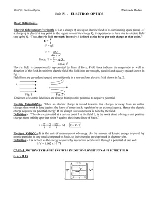
  • 1. Unit VI : Electron Optics Wankhede Madam Unit IV - ELECTRON OPTICS Basic Definitions:- Electric field intensity/ strength :- Let a charge Q sets up an electric field in its surrounding space (area) . If a charge q is placed at any point in the region around the charge Q, it experiences a force due to electric field sets up by Q. “Thus, electric field strength/ intensity is defined as the force per unit charge at that point.” E = 𝑭 𝒒 F = qE F = q Q 4πєoєr r2 Since, E = = q Q 4πєoєr r2 Electric field is conventionally represented by lines of force. Field lines indicate the magnitude as well as direction of the field. In uniform electric field, the field lines are straight, parallel and equally spaced shown in fig. 1. Field lines are curved and spaced non-uniformly in a non-uniform electric field shown in fig. 2. + + Fig. 1 Fig. 2 Direction of electric field lines are always from positive potential to negative potential Electric Potential(V):- When an electric charge is moved towards like charges or away from an unlike charges then work is done against the force of attraction & repulsion by an external agency. Hence the electric charge acquires the potential energy. If the charge is released work is done by the field. Definition:- “The electric potential at a certain point P in the field E, is the work done to bring a unit positive charges from infinity upto that point P against the electric lines of force.” V = = = = Ed E = V / d Electron Volt(eV):- It is the unit of measurement of energy. As the amount of kinetic energy acquired by atomic particles is very small compared to Joule, so their energies are expressed in electron volts. Definition:- It is defined as the energy acquired by an electron accelerated through a potential of one volt. 1eV = 1.602 x 10⁻¹⁹ J CASE- I MOTION OF CHARGED PARTICLE IN UNIFORM LONGITUDINAL ELECTRIC FIELD (i. e. v II E) -
  • 2. Unit VI : Electron Optics Wankhede Madam Let A & B are two plane parallel metals plates of equal area, separated by distance ‘d’ and insulated from each other. If a d.c voltage source s applied between two plates, then the plates are charged oppositely and an electric field is produced in the region between the plates. The field lines are directed from +ve to –ve. If the potential difference between A & B is V, then the electric field strength is given by E = V / d ------(1) Now assuming that it is a parallel plate capacitor, let an electron of mass ‘m’ and charge ‘e’ be placed at rest in uniform electric field and then it is released. This electron experiences a force due to electric field F = -eE ---------(2) -ve sign indicates that the force accelerates the electron in a direction opposite to the direction of electric field. Electron travels in a straight-line path opposite to the direction in which electric field is acting. CASE II :- Motion of particle perpendicular to uniform electric field (i.e. v ⊥ E) Consider an electron moving in a uniform perpendicular Electric field intensity E ⃗. Let, d - distance between two parallel plates. V - potential difference between two plates. vo- initial velocity acquired by the electron moving in x- direction VA- Accelerating Potential applied between cathode and anode inside Electron Gun. The electron moves along a parabolic path in a transverse electric field. Motion of an electron in a uniform magnetic field A static magnetic field does not act on an electron which is at rest. However when electron moving with a velocity v enters in a magnetic field, it experiences a magnetic force is given by FL = e(v x B) FL = evBsinθ -------(1) The direction of the force FL is neither along the direction of v or that of B, but lies along the normal to the plane containing both vectors v & B i.e., Lorentz force is always perpendicular to the displacement of the electron. The magnetic field does not produce any change in the speed or kinetic energy of an electron. Kinetic energy of a charged particle remains constant when it moves in a uniform magnetic field. (S- 15/3m) The magnetic field cannot change the speed ‘v’ and the kinetic energy of the electron. CASE- I:- Longitudinal uniform magnetic field / magnetic field parallel to initial velocity e e- B
  • 3. Unit VI : Electron Optics Wankhede Madam If an electron moves parallel to the magnetic field lines the, magnetic force (FL)on it is zero. i.e. FL = evBsinθ = 0 (since, θ = 0 ) similarly, if the electron moves opposite to the field, the magnetic force on it will be zero. i.e. FL = evBsinθ = 0 (since, θ = 180o ) As the force is zero, the acceleration is zero. Therefore the electron continues to move along the initial direction of motion without suffering any change in its speed or direction of motion. CASE- II:- Transverse uniform magnetic field / magnetic field perpendicular to direction of electron Let us now consider the case of an electron moving in a uniform magnetic field(B) with its initial velocity(v) perpendicular to the field. Let θ be an angle between v & B which is 90o . thus the magnetic force is given by FL = evBsinθ FL = evB --------(1) (since, θ = 90o ) (it is assumed that the magnetic field in into the page and indicated by crosses). This force cannot change the magnitude of electron velocity but deflects the electron continuously along a curvilinear path. The force FL provides the centripetal acceleration which is necessary for the uniform circular motion of the electron. Thus FL is a centripetal force acting on an electron. According to Newton’s law of motion, the centripetal force is given by, FC = FL = FC evB = r = -----------(2) r α mv (*This eqn shows that the radius is directly proportional to the momentum) Since all the parameters in eqn (2) are constant, thus r remains constant. Thus the locus of points at a constant distance from a centre point is a circle. Therefore an electron describes a circular path in a plane perpendicular to the magnetic field. Q. What are the shapes or trajectories of an electron in electric and magnetic field when? i) v parallel to E ---- straight line path ii) v perpendicular to E ---- parabolic path iii) v parallel to B ---- straight line path iv) v perpendicular to B ---- circular path
  • 4. Unit VI : Electron Optics Wankhede Madam Electric and magnetic field in cross field configuration Q.) What is crossed field configuration? Explain. Determine the velocity of the charged particle without any deviation? (S-16/3m) When uniform electric and magnetic fields are perpendicular to each other and act over the same region, then they are said to be in crossed configuration. Consider the pair of plane parallel metallic plates A & B which sets up the electric field acting vertically downward. The magnetic field of induction B is applied perpendicular to the electric field and acting into the page. When an electron passes through the region along a direction normal to both the fields then it experiences electric and magnetic field at the same time. The electric field deflects the electrons upward whereas the magnetic field deflects the electrons in downward direction. The force due to the electric field is, FE = eE And the force due to the magnetic field is, FL = evB If the magnitudes of the fields E and B are adjusted such that the force exerted by these fields on electron becomes equal to each other, hence the electron will not experience any force. Thus, FE = FL eE = evB v = E /B This shows that electrons experience a zero net force as the two forces balance each other and they will not deviate from their original straight line path and travel without change in the velocity v. Velocity Filter Q.) Explain the function of velocity filter. (S-13/3m) Q.) Explain the working of velocity filter. (W-13/3m), (W-15/3m) Q.) Explain the working of velocity selector with the help of necessary diagram (S-14/3m) Q.) Explain the working of velocity selector (S-15/3m) (W-16/3m) Q.) Explain why slower particles and faster particles require the same time for completing one rotation in magnetic field. (S-14/3m) The velocity filter is an electro-optic device, which uses uniform electric and magnetic fields in crossed field configuration for selecting a stream of charged particles of single velocity from a beam of charged particles having a wide range of velocities(𝐢. 𝐞. 𝐯 ± ∆𝐯). The selection of the particles of same velocity is done by using crossed-field configuration.
  • 5. Unit VI : Electron Optics Wankhede Madam Working: As shown in Fig. consider a beam of electrons with different velocities 𝑣±𝑑𝑣 enters the crossed field configuration. The electrons experience both electrostatic force FE due to the electric field and Lorentz’s force FL due to the presence of magnetic field. If the magnitude of the fields E and B are adjusted such that the electrostatic force balances the magnetic force, then those electrons having velocity ‘𝑣’ will not experience any force and continue to travel in a straight path undeviated. Thus, when FE = FL qE = q𝑣B … … … … … … … (6.18) ∴ 𝑣 = Fig. : Working of velocity filter The electrons moving with the velocities other than ‘𝑣’ are deflected upward or downward along OP or OQ. For those electrons which are moving with higher velocity (say 𝑣 = 𝑣 + 𝑑𝑣), 𝐹 > 𝐹 and they are deflected downward along OQ in circular path. The electrons which are moving with lower velocity (say 𝑣 = 𝑣 − 𝑑𝑣), 𝐹 > 𝐹 hence they are deflected upward along OP in parabolic path. These electrons which are deflected sideways are absorbed by the slit walls. Thus, a strictly homogeneous single velocity electron beam travelling along OR is obtained with the help of crossed fields. This arrangement is, therefore, known as a velocity filter or velocity selector. The arrangement is therefore known as velocity filter or velocity selector. The velocity filter is used in Bainbridge Mass Spectrograph. Numericals 1) An electron passes undeviated through velocity selector having E=104 V/m and B= 0.02T. Determine the speed of electron. (W-14/2m) Ans. v = E/B = 104 /0.02 = 50 x 104 m/s 2) An electron beam passes through magnetic field of 2x 10⁻³ Wb/m2 and electric field of 3.4x 10⁴V/m both acting simultaneously at the same point. The path of the electron remains unchanged. Calculate the electron speed. (S-13/3m) Ans. B=2x 10⁻³ Wb/m2 , E=3.4x 10⁴ V/m v = E/B = 3.4x10⁴ /2x 10-3 = 1.7 x 10⁷ m/s
  • 6. Unit VI : Electron Optics Wankhede Madam BETHE’S LAW (ELECTRON REFRACTION) Q.) What is Bethe’s law? Discuss similarities and differences between Bethe’s law and snell’s law. (S-13/3m) Q.) Explain Bethe’s law. (W-13/3m) Q.) Explain Bethe,s law with necessary diagram and state its similarities with snell’s law. (S-14/3m) Q.) Explain Bethes law with the help of necessary diagram and discuss the similarities with snell’s law. (W-14/4m) Q.) What is Bethe’s law? Discuss the refraction of electron beam across the boundary separating two equipotential regions. (S-15/4m) Q.) Discuss the refraction of electron beam across an equipotential surface. (W-15/3m) Q.) Explain Bethe’s law of electron refraction. (S-16/3m) Q.) State the law that governs the reflection of electron. In what way it resembles the snell’s law and in what way it differs from it. (W-16/3m) A nonuniform electric field is a field in which electric intensity varies from point to point. In such a field electric field lines are not straight and also not evenly spaced. On an equipotential surface, the electric potential remains constant and the electric field lines are normal to the surface at any point. Therefore, the normal to the equipotential surface shows the line of action of electric force on the electron. When a narrow beam of electron travels in a non-uniform electric field, it bends and follows a curved path. This bending of electrons by non-uniform electric fields is called as electron refraction. Fig.6.: Refraction of electron beam in non-uniform electric field Consider an equipotential surface AB. It is considered as the boundary across which the potential V1 abruptly changes to potential V2. Let an electron travel through the region I with a uniform velocity v1 and enter in region II. As the electron passes through the equipotential surface AB, it experiences a force which alters its velocity. Because the electric field exists only in the vertical direction the y component of electron velocity (normal component of electron velocity) vy undergoes a change whereas, , the X component of velocity (tangential velocity component) vx remains constant. The resultant velocity v2 in region II is different from v1. If V2 > V1, vy increases or if V2 < V1, vy decreases. Here V2 > V1 hence vy increases. The electron path is therefore bent nearer in the surface normal. The electron refraction that occurs at the equipotential surface is
  • 7. Unit VI : Electron Optics Wankhede Madam similar to the light refraction taking place at the boundary of rarer-to-denser medium. The equipotential surfaces such as AB play the role of refracting boundary in case of charged particles. As, the X component of velocity (tangential velocity component) remains constant in region-I and in region-II, we write, vx= vx’ v1 sinθ1 = v2 sinθ2 = ---------- (1) using v= in eqn (1) we get, = [ ]1/2 This relation is known as the Bethe’s law for electron refraction Explanation of Snell’s Law When a light ray passes from rarer medium to denser medium, it bends toward the normal. By snell’s law, 2 1 1 2 1 2 / / sin sin v v v c v c r i      SIMILARITIES AND DIFFERENCES BETWEEN BETHE’S LAW AND SNELL’S LAW SIMILARITIES 1) Both laws deal with the phenomenon of refraction. 2) When light ray travels from rarer to denser medium, it bends towards the normal. Similarly, electron beam bends towards the normal when it travels from low potential to high potential region. Therefore, angle of refraction is less than angle of incidence. 3) Velocity of light or that of electron beam changes after refraction. 4) Both light ray as well as electron beam follow the law of reversibility. 5) The ratio of refractive index of electrostatic fields is expressed in units of square root of volt. DIFFERENCES Table 1: Differences between Bethe’s Law and Snell’s Law
  • 8. Unit VI : Electron Optics Wankhede Madam S.No. BETHE’S LAW SNELL’S LAW 1. When the electron beam travels from a region of lower potential to higher potential, its velocity increases on entering the region of higher potential. When the light beam enters from rarer to denser medium, its velocity decreases on entering the denser medium 2. In terms of velocities, Bethe’s law can be written as θ θ = In terms of velocities, Snell’s law can be written as = Hence the order of velocities is reversed. 3. Bethe's law deals with refraction of electron beam at the boundary between two regions with different potentials. Snell’s law deals with refraction of light beam at the boundary between two media with different refractive indices. Above fig. shows the motion of an electron in a nonuniform electric field represented by equipotential surface separating equipotential regions of potential V1,V2,V3,V4 etc. At each surface electron path bends towards or away from the higher or lower potential region. It is observed that the electron motion occurs along a curved path in a non-uniform electric field. Electrostatic lens (Electron lens):- Principle:- When a stream of electrons travel through a non-uniform electric field it experience a change in direction. So its path is bent at each equipotential surface in the same way as a light ray is bent at an optical boundary (using optical terminology) .A stream of electrons may be called as an electron ray. Hence non- uniform electric fields can be used to focus a bundle of electron rays just as a convex lens focuses light rays. A non-uniform electric field produced by two coaxial metal tubes maintained at different potential can focus electron rays and therefore, such a system is called as ‘electron lens’. Construction:- An electron lens is made of two coaxial short cylindrical metal tubes T1 and T2 separated by some distance. The tubes are held at different potentials V1 and V2 respectively. V2 and V1 a non-uniform electric field is produced in the gap between the two tubes as shown figure. The equipotential surface are perpendicular to the electric field the electric field within the hallow space of the tube is weak and negligible.
  • 9. Unit VI : Electron Optics Wankhede Madam Figure:- Working :- Let us consider a bundle of electron rays enters in the double cylinder lens system through the tube T1 which is held at a lower potential V1. a) The electrons lablled as (1) move along the axis of the system, When it reached on the equipotential surface in the gap they experience an electric force which acts along the axis in forward direction. Therefore, the electrons gets accelerated towards tube T2 along axis without any deviation from their initial path of travel. b) The electrons lablled (2) on reaching the equipotential surface in the gap experience an electric force which acts at an angle to the direction of their motion. The force F experienced by electrons at the converse equipotential surface can be resolved into rectangular components FII and FI. FII = act parallel to the axis while FI= acts perpendicular to the axis. Due to the force F1, the electrons are deflected down towards the axis and because of FII electrons accelerated towards the T2. c) Similarly, the electrons lablled (3), are deflected up towards the axis and also accelerated forward, thus all off- the axis electron paths around the axis tends to converge towards the axis. However, on crossing the midplane MM’ of the gap, the converging electron rays encounter equipotential surface of concave shape. In the second –half of the gap, the normal components of electric force, F┴ is directed always from the axis for all off –axis as shown fig. and the Fǁ components is directed forward. As a result the electrons are accelerated forward but tend to diverge. Thus the first half of the gap acts like a convex lens where the electrons rays tends to converge and the second half acts like a concave which defocuses the rays.
  • 10. Unit VI : Electron Optics Wankhede Madam For every set of values of V1 and V2 the conveying action will be stronger than the diverging action. Because the electrons move slower in the lower potential region, they spend a larger in the first half of the gap and the impulse ‘F11 t’ is greater for the convergence interval. In the second half the electron move faster because of higher potential and the impulse ‘F11 t’ is smaller for divergence interval. Because of this action, the net result is that electron rays get focused. This double cylinder arrangement is called an electrostatic lens or electron lens. Comparison with the glass lens:- 1) Light rays are bent only at the two boundaries of a lens but electron rays are refracted continuously through successive equipotential surface. 2) The focal length of a glass lens is fixed, whereas the focal length of an electron lens may be varied by adjusting the potential V1 and V2 on the cylinders. Applications:- 1) Electron lens is the most important components of an electron gun used for producing a narrow intense electron beam. 2) Electron lens action is utilized in particle accelerates to focus charged particles into a narrow beam. CRO Q. Draw a schematic of Cathode Ray Tube and show its principle parts. Briefly describe their function. W-01(6m), W-11(3m) OR Draw the schematic of electrostatic CRT. Describe the role of (i) Electron gun (ii) Deflection system (iii) Fluorescent screen (iv) Aquadag coating S-07(5m) OR Which voltage controls the intensity of electron beam on the screen in CRT? What is the function of voltage given to the anode cylinders in it? S-09(3m) OR What is the use of aquadag coating in CRT? S-09(2m) OR Give the functions of each block of the CRO. W-02(2m), W-05(5m) OR State the functions of different blocks of CRO. S-08(3m), W-09(5m) OR Explain how the true shape of a voltage waveform is displayed on a CRO screen. (5m) OR Explain in brief the function of the time base circuit. W-06(4m), S-10(2m), S-12(3m) OR Explain the use of time base circuit in a CRO. W-07(5m) OR Explain how the actual waveform of the signal is traced on the CRO screen with the help of time-base generator. W-01(5m), S-05(3m) OR How is CRO used to display A.C. waveform? W-08(3m) OR Explain the necessity of time base circuit in the CRO. S-03(3m) OR Is it possible to display the waveform on the CRO screen without the time base generator. Explain. W-10(3m) Q.) Draw block diagram of CRO and explain how intensity of trace is controlled on screen. (S-13/4m) Q.) Explain the function of Aquadag coating on the screen of CRT. (S-13/2m) Q.) Draw block diagram of CRO. Explain function of time base generator. (W-13/4m)
  • 11. Unit VI : Electron Optics Wankhede Madam Q.) Draw neat and clean diagram of Cathode ray oscilloscope. Explain function of time base generator in brief. (S-14/4m) Q.) Draw schematic diagram of CRO and explain the role of aquadag coating in CRT. (W-14/3m) Q.) Draw block diagram of Cathode ray oscilloscope. (S-15/4m) Q) Draw block diagram of CRO. How can intensity and focusing of the trace on the screen can be controlled. (W-16/5m) Q.) Describe the role of Aquadag coating in Cathode ray tube. (S-15/2m) Q) Explain the role of acquadag coating in cathode ray tube. (W-16/2m) Q.) Draw block diagram of CRO. Explain the role of electron gun. (W-15/3m) Q. Draw the schematic of an electrostatic CRT, write the function of (i)Electron gun and (ii) Aquadag coating (S-16/2+2m) Block diagram of CRO CRO is a very important electronic measuring instrument. It is used to display and measure electrical signals, time interval, phase shift between two electrical signals, voltage and frequency of electrical signals. Basically CRO consists of seven major blocks a) Cathode ray tube b) Time base circuit c) Trigger circuit d) Vertical circuit e) Horizontal circuit f) High voltage power supply g) Low voltage power supply
  • 12. Unit VI : Electron Optics Wankhede Madam Working of various blocks: I) CRT: A cathode ray tube is a specially constructed vacuum tube in which an electron beam is controlled by electric and magnetic field which generated a visual display of input electrical signals on fluorescent screen.It consists of three main parts electron gun, deflection system and fluorescent screen. The CRT is like a conical flask, placed horizontally and sealed at its one end. The electron gun contains several electrodes mounted at one end of the tube. All electrodes are connected by using basepins. The deflection system consists of two pairs of parallel metal plates. These plates are oriented in such a way that the orientation is perpendicular to the axis of the CRT. The screen consists of a thin coating of phosphors deposited on the surface of curve of envelope. The inner surface of two side ends contains coating of graphite material which is known as acquadag coating. a) Electron gun: An electron gun is a device which is used to produce a narrow electron beam of high intensity. Principle: It is based on the principle of non uniform electric field that cause bending of electronic paths. Construction: the electron gun consists of a cathode (K), a filament heater (F), control grid (G) and three anodes A1, A2 and A3. The cathode K is a short hollow cylinder made up of nickel. The front face of cathode is coated with thoriated tungsten or barium and strontium oxide that helps for thermionic emission to occur at moderate temperature 700o to 900oC. The cathode surrounded by the control grid having a small opening in its front face to pass the electrons. Anode A1, A2 and A3 are coaxially situated beyond the cathode. Working: When power is switched on, the filament heats up the cathode. The electrons are emitted from the cathode and pass through the control grid. The control grid is held at negative potential. When the grid is at less negative potential then more number of electrons pass through it and intensity of the luminous spot on the screen is high. Similarly, when the grid is held at high negative potential then less number of electrons pass through it and intensity of the luminous spot on the screen is less. Thus, the grid acts as a gate and regulates the passage of electrons through it. Thus control grid is used to control the intensity of the luminous spot on the screen. Anode A1 accelerates the beam of electrons. The grid G and A2 forms the first lens which is used to prefocusses the electron beam and known as prefocussing lens. A2 and A3 forms the second lens which focuses the electron beam and convert it into s fine spot which is seen on the screen. b) Deflection System: After emerging from the electron gun, a narrow and accelerated electron beam passes toward the fluorescent screen, but before striking, theses beam passes through the deflection system. The deflection system consists of two pairs of metals plates, aligned parallel to each other. These two pairs are perpendicular to each other and also to the axis of CRT. When a potential difference is applied to the horizontal plate, a uniform electric field is produced in vertical direction. This plate causes a vertical deflection and hence the set of deflection plates are called vertical deflection plates (VDP) also called Y-plates.
  • 13. Unit VI : Electron Optics Wankhede Madam Similarly, when potential difference is applied to the vertical plate, the uniform electric field is produced horizontally and causes a horizontal deflection of the beam, hence the set of plates are called horizontal deflection plates (HDP) and are called X-plates. 1) When voltages are not applied to X and Y plates, the electron beam travels straight and strikes on the screen producing a bright spot at the centre. 2) When dc voltage is applied to Y plate in such a way that upper plate is at positive potential and lower plate is at negative potential then electron beam is attracted toward upper plate and the spot moves upward. 3) When lower plate is made positive and upper plate is negative then bright spot will move downward on the screen.
  • 14. Unit VI : Electron Optics Wankhede Madam 4) When a dc voltage is applied to X-plate in such a way that left plate is +ve and right plate is –ve then spot moves toward left plate. 5) When left plate is –ve and right plate is +ve, the spot moves toward right plate. 6) When dc voltages are applied to both X and Y plates, the electron beam gets deflected along the directions of their resultant.
  • 15. Unit VI : Electron Optics Wankhede Madam c) Fluorescent Screen: The interior surface of circular front face is coated with thin layer of phosphor. The spot on the screen continues to glow for a short period of time even after the electron beam moves away. This coating is made thin to allow thw light to pass through the screen and viewed from outside the CRT. Aquadag Coating : 1) When electrons strikes the screen, they tends to charge the screen negatively and repels the electrons arriving afterwards. It will reduce the number of electrons reaching the screen and also the brightness of the glow. 2) Similarly, as electrons emitted from the cathode are in large number, the cathode assumes gradually a +ve charge and again intensity of the glow on the screen reduces. Hence the cathode is to be replenished with electrons. The acquadag coating is the conducting coating of aqueous solution of graphite which is used to complete the electrical circuit from screen to cathode. The electrons striking the fluorescent screen not only cause emission of light but produces secondary emission of electrons. The secondary electrons are attracted by the anode A3 and the electrons are returned to cathode through the ground. Note: When ac signal voltage is applied to the Y plate the beam moves up and down along vertical line in steps with varying voltages. The successive position of the spot cannot be displayed when signal frequencies are greater than 20Hz. The phosphor continue to glow for a short time after the electron beam passes, due to persistence of vision and the path of the beam across the screen is seen as a vertical line. It is called trace, the length of the trace corresponds to the peak to peak voltage Vp-p of the applied signal. Similarly horizontal motion of the electron beam is produced when an ac voltage is applied to X-plate. II) Vertical circuit: the signal is applied to Y input. It goes through ac-dc-gnd switch. When the switch is set in ac position then a capacitor is in series with the switch which allows ac signals to pass and blocks the dc components. When the switch is set in dc, the signals is directly coupled. When the switch is set in gnd, the signal containing ac and dc components is isolated and hence no deflection is obtained on the screen. The signal amplitude can be increased or decreased to obtain an adequate deflection on the screen by the volt/cm control (to get proper deflection on the screen). III) Horizontal circuit: The voltage to X plate can be applied form internal source or external source. When the switch is kept in external mode, the X plates are disconnected from the internal source. A signal connected to X input passes to the X plate through an attenuator, preamplifier and horizontal amplifier. The output of horizontal amplifier is fed to X plate. When the switch is kept in INT position a ramp voltage produced by an internal time base circuit is applied to the horizontal amplifier.
  • 16. Unit VI : Electron Optics Wankhede Madam IV) Low voltage power supply: Low voltage power supply provides power to all the electronic circuits such as trigger circuit, time base generator etc. it gives an output of the order of 400V. V) High voltage power supply: The high voltage power supply provides power to circuit i.e. the electrodes in the electron gun. It supplies voltage of the order of 1600 to 2200 volts. VI) Time base circuit: It consists of time base generator. In the signal the voltage varies as a function of time which requires the beam to move horizontally that covers equal distances in equal interval of time. 1) When the voltage is applied to X plate it rises through equal amount of voltage per unit time. 2) Secondly at the end of horizontal motion, the beam should return to the starting point after completing one rotation, which is known as ramp voltage. “ Ramp voltage is the voltage varies linearly with time.” The time base generator is a variable frequency oscillator that produces an output voltage of sawtooth shape known as sawtooth voltage. [If a harmonic voltage is applied to X plates, voltage is applied to X plates, the voltage varies through different amount in equal interval of time.]  Time base generator is a variable frequency oscillator that produces time base voltage/ or sweep voltage. This voltage is fed internally to X-plates of CRT to produce true shape of the signal on the screen of CRO.  True shape of the input signal voltage cannot be observed through vertical motion of the beam.  It can be displayed on the screen only if the beam is made to move simultaneously in a horizontal direction by equal distances in equal interval of time. This is done by Time base circuit.  The sweep voltage starts from some initial value (V)-max , increases linearly with time to (V)+max . This time is known as sweep time ts, as it is sweeping from negative to positive maxima, then it suddenly returns to its value (V)-max again, this time is known as retrace time tr .  The time taken by the electron beam to start from (V)-max and reach (V)+maxis called sweep time ts.  The time taken by the electron beam to drop from (V)+max to (V)-maxis called retrace time or fly back time tr.  The sum of sweep time (ts) and retrace time (tr) is called sweep period (TS). TS = ts + tr
  • 17. Unit VI : Electron Optics Wankhede Madam At t = 0, the ramp voltage is at its –ve max on the RHDP, the voltage rises uniformly with time and the beam moves towards the right side on the screen. When ramp voltage reaches to zero, the beam will come to the centre and when voltage increases the beam continues to move toward right end of the screen. When the voltage drops instantaneously to a minimum value the spot is whipped (sweep) back across the screen to its starting point on left edge from where it repeat the next cycle. Hence ramp voltage is also called as sweep voltage or sawtooth voltage. X-axis of the screen not only denotes amount of horizontal deflection but also the time covered therefore it is called time base voltage. The time taken by the sweep voltage to rise from its maximum negative voltage to its maximum +ve voltage is known as sweep time or trace time (ts). the time taken by the sweep voltage to dip from its positive maximum to negative maximum value is called fly-back time or retrace time (tr). T sweep = ts + tr = ts Q) Why ramp voltage is necessary? OR What are the conditions that must be fulfilled by the horizontal voltage in order to trace the true wave shape of signal on the CRO screen? CRO is used to measure the signal as a function of time. Signal which is to be tested is applied to y- input of CRO. If ac signal voltage is given to y-plates, it makes the electron beam to move up and down along vertical line so to reproduce faithful display of wave shape of signal on CRO screen it is essential. 1) To spread the deflected electron beam horizontal through equal distances in equal interval of time and 2) After completing one cycle, the beam should return to the starting point to repeat the next motion (cycle). The ramp voltage fulfils both these condition. Q) What is Blanking? How is it achieved? Blanking is the method of making retrace path of electron beam invisible during flyback time. Retrace path can be made invisible by applying a high negative voltage pulse to the control grid in electron gun which turns off electron beam momentarily. Display of true shape of signal  As the signal is applied to Y-plates and sweep voltage to the X-plates, the electron beam is subjected to two forces acting in perpendicular direction to each other.
  • 18. Unit VI : Electron Optics Wankhede Madam  The deflection of the beam at any instant occurs along the direction of the resultant of the two forces.  As time progresses, the resultant change in magnitude and direction and the beam displays the actual shape of the signal on the screen. Q) What is synchronization ? How it is achieved in a CRO? S-11(3m) OR Mention the function of a trigger circuit. S-01, 10(2m) Q.) What are Lissajous patterns? Define synchronization. How the intensity of the trace on the screen is controlled? (S-16/1+1+1m) Q.) What is synchronization? (S-14/2m) To get the steady and stable wave pattern on the CRO screen, horizontal deflection of electron beam should start at the same point of the input signal in each sweep cycle. When it occurs it is said that horizontal sweep voltage is synchronized with input signal. “Synchronization is the method of locking of frequencies of both time base generator (x plate) to the frequency of the input signal (y plate)”, to get a stationary display of wave pattern on CRO screen. Signal is synchronized only when the following conditions are satisfied. Fsignal = nfsweep 1/Tsignal = n(1/Tsweep) Tsweep = n Tsignal Eg. 1. If signal frequency is 50Hz and sweep frequency is 50Hz Fsignal = nfsweep 50 = n 50 n = 1 Tsweep = Tsignal Eg. 2. If signal frequency is 100Hz and sweep frequency is 50Hz Fsignal = nfsweep 100 = n 50 n = 2
  • 19. Unit VI : Electron Optics Wankhede Madam Tsweep = 2 Tsignal VII) Trigger Circuit: Synchronization of sweep and input signal voltage can be achieved by triggering method. The role of trigger circuit is to make ensure that the horizontal sweep begins at its specific time in the period of the vertical input signal. Trigger Circuit produces trigger pulse which triggers the time base circuit to produce time base voltage.It Synchronizes sweep voltage and input signal voltage. Synchronization is the method of locking of frequency of time base generator (x- plate) with the frequency of the input signal (y- plate) to get a stationary display of wave pattern on CRO screen”. i.e., 𝒇𝒔𝒊𝒈𝒏𝒂𝒍=𝒏𝒇𝒔𝒘𝒆𝒆𝒑 or 𝑻𝒔𝒘𝒆𝒆𝒑=𝒏𝑻𝒔𝒊𝒈𝒏𝒂𝒍 To achieve the condition of Synchronization, a portion of input signal is fed to the trigger circuit of the time base circuit Q) What is function of delay line? During the generation of trigger pulse, ramp voltage, the input signal is being fed through a delay line that delays the input signal before it is further amplified and fed to y-plates. So delay line gives enough time for developing trigger and the starting of ramp voltage. Q. Explain how intensity and sharpness of the trace on the screen are controlled. W-04(3m), S-11(2m), W-11(3m) Ans. Intensity control: The intensity of the display depends on the number of electrons striking the screen. Grid voltage regulates the number of electrons coming out of the aperture and hence grid voltage regulates the intensity of the display. When the grid is at less negative potential then more number of electrons pass through it and intensity of the luminous spot on the screen is high. Similarly when the grid is held at high negative potential then less number of electrons pass through it and intensity of the luminous spot on the screen is less. Thus the grid acts as a gate and regulates the passage of electrons through it. Thus control grid is used to control the intensity of the luminous spot on the screen. Sharpness/ Focussing control: The three anodes A1, A2 and A3 are kept at different potentials from the electrostatic lens which focuses the beam to a single spot on the screen. Hence, the potential on these anodes, controls the sharpness of the display on the screen. Applications of CRO
  • 20. Unit VI : Electron Optics Wankhede Madam CRO is used to measure variety of electrical parameters, some of quantities measured with its help are described as follows. 1) Study of waveform: The signal under study is applied at the y-input terminal and the sweep voltage is internally applied to x-plates. The waveform of the signal is displayed on the screen. 2) Measurement of dc-voltages: Initially the trace is adjusted to the center of the screen. The dc- voltages under study is applied at y-input. The trace gets deflected upward or downward depending upon the polarity of the applied voltage. The deflection is read on the graticule and by multiplying it with deflection factor (volt/cm), the magnitude of the unknown voltage is obtained. Displacement = 1cm Position of vertical amplifier = 1V/div Applied voltage = 1x1 = 1V 3) Measurement of ac-voltages: The trace is adjusted at the centre of the screen and ac-voltage under study is applied to y-input. The peak distance is measured and on multiplying it by deflection factor Vp-p is obtained. The values of Vrms & Vavg are then calculated by using formulae. Vp = and Vrms = √ = 0.707 Vp Vavg = 0.636 Vp 4) Measurement of frequency: Method I: A sinusoidal signal whose frequency is to be determined is applied to y-input. The time base control is adjusted to obtained 2 or 3 cycles of the signal on screen. The horizontal spread of one cycle is noted. By multiplying it with time- base sensitivity, the time period of the signal is obtained. Then the reciprocal of the time period gives the frequency of the signal. T = (horizontal spread of 1 cycle) x (position of time-base sensitivity) F = 1/T
  • 21. Unit VI : Electron Optics Wankhede Madam   Time base sensitivity (x) =2 ms/cm  Spread of wave (l) = 5.6 cm  Time period T = 2x5.6 =11.2 ms  Frequency f = 1/T = 1/11.2ms = 1000/11.2 = 89.28Hz. 5) Alternative method using Lissajou’s pattern: frequency of test signal can be measured using lissajou’s pattern. When two sine waves oscillating in mutually perpendicular planes are combined, different types of closed loop patterns are obtained. They are called as lissajou’s pattern. If two sine waves of different frequencies are applied to x & y plates of a CRO then closed loop pattern are displayed on the screen. A stable pattern is obtained when ratio of the frequencies is an integer. The number of points at which the loops are touching the horizontal and the vertical tangents i.e. LH and LV are noted. The unknown frequency is given by 𝑭𝒀 = 𝑳𝑯 𝑳𝑽 𝑭𝑿
  • 22. Unit VI : Electron Optics Wankhede Madam Eg. When two voltages are applied to x & y plates and ratio of frequency 2:1 (fig. g) i.e. = let the known and unknown signal source are connected to x & y plates respectively, by varying frequency of the known source a stable loop pattern is displayed. 6) Measurement of phase difference or phase angle: when two sine waves oscillating in mutually perpendicular planes are of the same frequency, the lissajou’s pattern takes the form of an ellipse. The phase angle Ø can be calculated by using formula Ø = sin-1 ( ′ ′ ) BAINBRIDGE MASS SPECTROGRAPH
  • 23. Unit VI : Electron Optics Wankhede Madam Q.) Explain construction and working of Bainbridge Mass spectrograph. (W-13/5m)(W-15/4m) (S-16/3m) Q.)Describe the working principle of a Bainbridge mass spectrograph with neat sketch. (S-13/5m) Q.) Discuss the construction and working of velocity selector to produce the mono-velocity beam of charged particle. (W-14/3m) It is an instrument which, by using electric field and magnetic fields, separates isotopes from a stream of positive ions of an element and measures their individual masses. This instrument separates ions of different masses, hence called a mass spectrograph. It was designed by K. T. Bainbridge in 1933. Principle: Bainbridge mass spectrograph is based on the principle that a uniform magnetic field acting normal to the path of ions having the same velocity deflects the ions of different masses along several circular paths of different radii. The radius of each circular path is linearly related to the mass of the ion. Velocity selector is used to produce monovelocity ion beam. Construction: It mainly consist of 1) Velocity selector 2) Analysing chamber or momentum selector. Bainbridge mass spectrograph is vacuum chamber placed in a uniform magnetic field, acting perpendicular to its larger surface. Positive ions of variable speed coming from ion-source are collimated by the slits S1 and S2. Deflection plates P and Q are placed next to the slits. These are charged and produce electric field. Electric field and transverse magnetic fields constitute a velocity selector/ filter. Slits S3 is arranged to collimate the narrow monovelocity ion beam and allows it to pass through the analyzing chamber. A photographic plate is mounted in the analyzing chamber in line with slit S3. Working:
  • 24. Unit VI : Electron Optics Wankhede Madam An element under study is taken in the form of gas. The gas is ionized when the potential difference across the electrodes. Positive ions are accelerated and conducted into the mass spectrograph through the slits S1 and S2. These ions are of variable speed/velocity and of variable mass. They pass through the velocity filter, after collimation through S1 and S2. The electric field strength is adjusted such that ions having a velocity v = E/B merge out of the filter without deflection and pass through the slits S3. (ions having a velocity v=E/B i.e. FE = FL for ions). Ions having velocities different form v get deflected away and are absorbed by the walls of the chamber. Monovelocity ions after passing through the slit S3 enter the transverse uniform magnetic field B. this transverse field B deflect these ions in a circular path. Monovelocity ions having same values get focused at the same point on the photographic plates mounted in line with field acting on the chamber constitutes a momentum selector and separates out ions of different masses. Different isotopes produce multiple vertical lines. The visual record of ions in the form of vertical lines on the photographic plates is called mass- spectrum. Q. Show that mass-scale is linear in Bainbridge mass-spectrograph? Ans. Isotopes positions are recorded as vertical lines on photographic plates held in the analyzing chamber of Bainbridge mass spectrograph. The distance of any line is measured from the centre of the slit S3 through which the isotopes enter the evacuated analyzing chamber. Let ‘x’ be the distance of a line marked by a singly ionized ion of mass M with velocity v, ‘R’ be the radius of its circular path. X = 2R = diameter of circular path of ion X = 2( ) (since v = E/B) X = ----------(1) ∴ M = --------(2) ⇒ M α x -----------(3) (since is constant for given E & B) Eqn (3) is the equation of straight line. Thus mass scale is linear. Derivation of line separation: Let M1 and M2 be the masses of two isotopes and if x1 and x2 respectively are the distance from the centre of the slit S3, then by using equation (1) x1 = , x2 = The line separation is given by, Δx = (x2-x1) = (M2-M1)
  • 25. Unit VI : Electron Optics Wankhede Madam . LIST OF FORMULAE MAGNETIC FIELD: TRANSVERSE MAGNETIC FIELD:  Lorentz force𝐹 = q (𝑣 ⃗ × 𝐵 ⃗) = q v B sin𝜃 = qvB when 𝑣 ⃗ is perpendicular to 𝐵 ⃗ for electron, 𝐹 = e(𝑣 ⃗ × 𝐵 ⃗) = evBsin𝜃 = evB  Radius R of circular path = for electron, R of circular path = CROSSED ELECTRIC AND MAGNETIC FIELD CONFIGURATION  F E = F L  𝑣 = BETHE LAW OF ELECTRON REFRACTION  Bethe’s law in terms of potential =  Bethe’s law in terms of velocity of an electron Sin Sin = BAINBRIDGEMASS SPECTROGRAPH  The line separation between the isotopic masses (𝑥 − 𝑥 ) = (𝑀 − 𝑀 )  To find unknown mass of an element (𝑀 − 𝑀 ) = (𝑥 − 𝑥 ) SOLVED NUMERICALS 1. An electron beam passes through a magnetic field 2×10⁻³ Wb/m2 and an electric field of 3.4×10⁴ V/m, both fields being normal to each other and acting simultaneously in the same region. The path of electrons remains unchanged. Calculate the electron speed? (3M)[Summer-13&17] Ans. Given: B = 2×10⁻³Wb/m2, E = 3.4×10⁴V/m Solution: 𝑣 = = . = 1.7 × 10 m/s 2. Determine the velocity of ions that pass undeflected through crossed E and B fields for which E=7.7 kV/m and B=0.14T. (3M)[Winter-17] Ans. Given: B = 0.14T, E = 7.7kV/m= 7.7×10³ V/m Solution: 𝑣 = = . . = 5.5 × 10 m/s 3. An electron passes undeviated through a velocity selector having E=104V/m and B=0.02T. Determine the speed of electron. (2M)[Winter-09,14& 19] Ans. Given: B = 0.02T, E = 104 V/m Solution: 𝐯 =
  • 26. Unit VI : Electron Optics Wankhede Madam = . = 50 × 10 m/s 4. A positive ion beam moving along the x-axis enters a region of uniform electric field of 3kV/m along Y-axis and magnetic field of 1 KG along z-axis. Calculate the speed of those ions, which pass undeviated. What will happen to ions, which are moving (i) Faster, (ii) slower than these ions? (4M)[Winter-00 &02] Ans. Given: B = 1KG = 103 G = 103×10-4Wb/m2 = 0.1T, E= 3kV/m = 3×10³V/m Solution: Speed 𝑣 = = . = 3 × 10 m/s -------- for un-deviated ions. Ions moving faster than these ions will be deflected towards magnetic field along circular path and slower ions will be deflected towards electric field along parabolic path. Both deviated ions will be absorbed by slit walls of velocity filter. 5.Electrons accelerated under a potential of 250V enters the electric field at an angle of incidence of 500 and gets refracted through an angle of 300. Find the potential of second region. Find the potential difference between the two. Ans. Given: V1=250V θ1=500 θ2=300 V2=? Solution: θ θ = Sinθ Sinθ = V 250 ⇒ V = 586.8V ∴ Potential difference = V − V = 586.8 − 250 = 336.8V 5. An electron beam enters from a region of potential 75 V into a region of potential 100V, making an angle of 450 with the direction of electric filed. Find the angle through which the beam refracts. (3M)[Summer- 13](3M)[Winter-19] Ans: Given: V1=75V θ1=450 V2=100V θ2=? Solution: θ θ = ⇒ Sin 45 Sin θ = 100 75 Sin θ Sin 45 = 75 100 Sin θ = Sin 45 75 100 ⇒ θ = 38° a. 6. A. In a Bainbridge mass spectrograph, singly ionized atoms of Ne20passes into deflection chamber with velocity of 105 m/sec. if they are deflected by a magnetic field of flux density of 8 x 10⁻² Wb/m2, Calculate radius of the path of singly ionized Ne20atom. Ans: Given: v=105 m/sec B=8 × 10⁻² Wb/m2
  • 27. Unit VI : Electron Optics Wankhede Madam M=20 a.m.u. = 20 ×1.67x10-27 Kg q=1.602 × 10⁻¹⁹C r=? Solution:r = r = 20 × 1.67 × 10 × 10 1.602 × 10 × 8 × 10 = 0.26m = 26cm. Q.6.B. In a Bainbridge mass spectrograph, singly ionized atom of Ne20 passes into deflection chamber with the velocity 103 m/sec. If they are deflected by a magnetic field of flux density 0.07Wb/m2 .Calculate the radius of path of singly ionized Ne20 atom. (3)S-18 Ans. Given: B= 0.07 wb/m2 v= 103 m/sec M= 20 amu= 20 x 1.67 x 10-27 kg = 3.34X10⁻²⁶ kg, q = 1.602 x 10⁻¹⁹ C, R=? Solution: 𝑅 = = . . . = 2.978 x10⁻³ m 7. The electric field between the plates of a velocity selector is 150V/cm and the magnetic field common to both the velocity selector and the analyzing chamber is 0.5T. If the source contains two isotopes of magnesium Mg 24,Mg25 which are single charged, then find the distance between the lines formed by these isotopes on photographic plate. (4M)[Winter-15&16] Ans: Given:E=150 V/cm= 150×102 V/cm B=0.5T M1=24×1.67×10-27Kg M2=25×1.67×10-27Kg q =1.602×10⁻¹⁹ C ∆x=? Solution: Δx = 2E(M − M ) B q Δx = × × ( )×1.67X10⁻²⁷ ( . ) ×1.602x 10-19 = 1.245 mm 8. A. In a Bainbridge mass spectrograph, the electric field used is 8 x 10¹⁴ V/m ,the magnetic field common to both places is 0.2 Wb/m2. If the ion source consists of singly ionized neon isotopes of atomic masses 20 and 22, calculate linear separation of lines formed on photographic plate. (3M)[Summer-19,Winter-13] Ans. Given: E=8 × 10¹⁴ V/m B=0.2 Wb/m2 M1=20 ×1.67 x10-27Kg M2=22 ×1.67 x10-27Kg q =1.609 × 10⁻¹⁹C ∆x=? Solution:𝛥𝑥 = ( ) = × × ×( )×1.67X10⁻²⁷ ( . ) ×1.609x 10⁻¹⁹ m 8 10 3 . 8   Q.8.B. In a Bainbridge mass spectrograph, the electric field used is 8 x 10⁴V/m, the magnetic field common to both places is 0.55 wb/m2. If the ion source consists of singly ionized neon isotopes of atomic masses 20 and 22, calculate linear separation of lines formed on photographic plate. (3) W- 12 Ans.Given: M1= 20 a.m.u = 20x 1.67 x 10-27 Kg
  • 28. Unit VI : Electron Optics Wankhede Madam M2= 22 a.m.u =22 x 1.67 x 10-27 Kg B= 0.55 wb/m2 , E= 8 x 10⁴ V/m, q=1.602x10⁻¹⁹ c ∆𝑥 =? Solution: Linear Separation∆𝑥 = (𝑀 − 𝑀 ) meters = 𝟐𝑿𝟖𝑿𝟏𝟎𝟒(𝟐𝟐 𝟐𝟎)𝑿𝟏.𝟔𝟕𝑿𝟏𝟎 𝟐𝟕 𝟏.𝟔𝟎𝟐𝑿𝟏𝟎 𝟏𝟗𝑿(𝟎.𝟓𝟓)𝟐 = 11x10-3 m 9. A. In a Bainbridge mass spectrograph, the magnetic field in the velocity filter is 1Tesla and the ions having a speed of 4 x 10⁶ m/s pass through it undeflected. (a)What should be the electric field between the plates? (b)If the separation of plates is 0.5 cm, what is the potential difference between the plates? Ans. Given: B=1Tesla v=4 ×10⁶m/sec. d=0.5cm=0.5×10⁻² m. E=? V=? Solution: (a)𝑣 = ⇒ 𝐸 = 𝑣𝐵 m V / 10 4 1 10 4 6 6      (b) 𝐸 = ⇒ 𝑉 = 𝐸. 𝑑 = 4 × 10 × 0.5 × 10 = 2 × 10 𝑉 9. B. In Bainbridge mass spectrograph a potential difference of 1000 V is applied between two plates separated by 1 cm and magnetic field B= 1T. Then the velocity of undeflected positive ions in m/s from the velocity selector is____ Ans. Given: B=1Tesla v=?. d=1cm=1×10⁻²m. E=? V=1000V Solution: 𝐸 = = 10-2 = 10 V/m 𝑣 = 𝐸 𝐵 = 10 1 = 10 𝑚/𝑠 10. The electric field between the plates or velocity selector in Bainbridge mass spectrometer is 1.2 x 10⁵ V/m and magnetic field in both regions is 0.6T. A stream of singly charged neon ions moves in a circular path of radius 7.28 cm in magnetic field. Determine mass number of neon isotope. (3M)[Summer- 15,17] Ans. Given: E = 1.2 ×10⁵ V/m B = 0.6T R = 7.28 cm = 7.28 × 10⁻² m Solution: 𝑅 = 𝑀𝐸 𝑞𝐵 ⟹ 𝑀 = 𝑅𝑞𝐵 𝐸
  • 29. Unit VI : Electron Optics Wankhede Madam = 7.28 × 10 × 1.602 × 10 × 0.6 1.2 × 10 = 3.49 × 10 kg = 3.49 × 10 1.67 × 10 = 20.89amu = 21 11. In a Bainbridge mass spectrograph, the electric field used is 8 x 10⁴ V/m, the magnetic field common to both places is 0.2 Wb/m2 . If the ion singly ionized atom of Mg26 passes into analyzing chamber with velocity 104 m/s. Calculate the radius of path of singly ionized Mg26 atom. (3M)[Winter- 15] Ans. Given: E = 8 × 10⁴ V/m B = 0.2 Wb/m2 M = 26 × 1.67 x10-27 Kg R = ? Solution: 𝑅 = = 26 x 1.67 x10 x 10 0.2 × 1.602x 10-19 = 0.013𝑚 12. The element Tin is being analysed in Bainbridge Mass Spectrograph amongst the isotopes present of masses 116 and 120. The electric and magnetic fields are 30 KV/m and 0.3 Wb/m2 at both the places respectively. Find linear separation between the lines produced on the photographic plate by singly charged ions of Tin 116 and 120. (3M)[Summer-18] Ans. Given:E = 30 KV/m B = 0.3 Wb/m2 M1 = 116 × 1.67 x10-27Kg M2 = 120 ×1.67 x10-27Kg q =1.609 × 10⁻¹⁹C ∆x=? Solution: 𝛥𝑥 = ( ) = × × ×( )×1.67X10⁻²⁷ ( . ) ×1.602x 10-19 =0.027m 13. In a Bainbridge mass spectrograph, the electric field used is 25 KV/m, the magnetic field is 0.2 Wb/m2. The element Tin is being analyzed having isotopes of masses 116 and 120. Find linear separation between the lines produced on the photographic plate by singly charged ions of Tin 116 and 120. (3M)[Winter-18] Ans. Given: E = 25 KV/m B = 0.2 Wb/m2 M1 = 116 × 1.67 x10-27Kg M2 = 120 × 1.67 x10-27Kg q =1.609 × 10⁻¹⁹C ∆x=? Solution: 𝛥𝑥 = ( ) = 2 × 25 × 10 × (120 − 116) × 1.67X10-27 (0.2) × 1.602x 10-19 = 0.052m