
Recommended
More Related Content
Similar to CSCMPE 3430, sp16 – Assignment 5 (30 points total) Due S.docx
Similar to CSCMPE 3430, sp16 – Assignment 5 (30 points total) Due S.docx (20)
More from annettsparrow
More from annettsparrow (20)
Recently uploaded
Recently uploaded (20)
CSCMPE 3430, sp16 – Assignment 5 (30 points total) Due S.docx
- 1. CS/CMPE 3430, sp16 – Assignment 5 (30 points total) Due: Saturday May 7 th , 11:59 pm on Blackboard Instructor: Dr. Lei READ: Sections 8.1-8.2, 8.4, Tables 8.2-8.3, Figures 8.2, 8.11- 8.12, 8.16 of Spring 2016 Doering text IMPORTANT: Submit all answers onto Blackboard using Logicworks .cct files. Use Excel spreadsheets to generate text, truth tables and K-maps, and copy and paste into the .cct files. In this assignment, you are to implement the ALU for the MIPS 3-stage pipeline CPU. The ALU is a combinational circuit that executes arithmetic, logic, slt, and shift instructions for the CPU. The ALU takes two 32-bit operands as inputs, and produces a 32-bit output. The ALU also takes in a function code that specifies the operation to be performed on the 32- bit inputs. Consider the following MIPS instructions in Table 8.2 – add, addu, sub, sub, and, or, xor, nor, slt (set-less- than), sltu (set-less-than-unsigned). The table shows the machine code of each instruction, and each machine code has
- 2. a 6-bit function code in the func 5:0 column. This function code signals to the ALU which operation to perform, and one function code uniquely corresponds to one instruction. Table 8.3 has C/C++ implementations of each MIPS instruction. Familiarize yourself with the high-level ALU implementation on Figure 8.12, with some details on Figure 8.11. The A input bus is the A31..0 input. The B input bus is the B31..0 input. The D output bus is the 32-bit D31..0 output. The func bus is the 6-bit function code input. The sa bus is the “shift amount” input, which is only used during shift operations. Those instructions are the sll, srl, sra, sllv, srlv, and srav instructions on Table 8.2. The implementation consists of a set of 32 slices. All slices are the same except for Slice 0 and slice MSB. The inputs to all slices except for Slice 0 are the following: a) A 6-bit function code input, corresponding to values in the func5:0 column of Table 8.2. This is the func bus input of each slice, which contains the 6 bits. b) A 1-bit “A” input, which is a single bit of the 32-bit A31..0 input of the overall ALU. c) A 1-bit “B” input, which is a single bit of the 32-bit B31..0 input of the overall ALU. d) A 1-bit “C” input (on the right side of each slice), which is equivalent to the “carry-in” input of a full-adder circuit. The outputs of each slice except for Slice MSB are the
- 3. following: a) A 1-bit “R” output, which is the result for any arithmetic (add, subtract), logic (and, or, xor, nor), or slt operation. b) A 1-bit “g” output, which is equal to 1 if the slice “Generates” a carry output. For instance, during an addition operation, a slice generates a carry output if both “A” and “B” inputs are 1. c) A 1-bit “p” output, which is equal to 1 if the slice “Propagates” a carry input to become a carry output. For instance, during an addition operation, a slice propagates a carry input if either “A” or “B”, or both, inputs are “1”. Slice MSB has an additional slt output, which is used only during an slt operation. An slt operation compares the 32-bit numbers A31..0 and B31..0, to see if A31..0 is less than B31..0. If so, then the slt output is 1. Otherwise, the slt output is 0. The slt output bit can only be performed in Slice MSB, because it needs the A31, B31, and D31 bits for its computation. The slt output bit is then sent to Slice 0, which sends the output to D0. All other output bits D1-D31 are set to 0. Hence, during an slt operation, the 32-bit output D31..0 is equal to either a 1 (i.e. 0000 0000 0000 0000 0000 0000 0000 0001), or a 0 (0000 0000 0000 0000 0000 0000 0000 0000). Lastly, Slice MSB also has an overflow output, which
- 4. indicates if arithmetic overflow occurred during addition or subtraction, and slice 0 does not have a “C” input. CS/CMPE 3430, sp16 – Assignment 5 (30 points total) Due: Saturday May 7 th , 11:59 pm on Blackboard Instructor: Dr. Lei When implementing an addition/subtraction operation using Full Adder circuits, the carry output of the Full Adder for each bit is normally fed to the carry input of the Full Adder for the next bit. This is called the “ripple-carry” method. The ALU slices are like the Full Adder circuits, where each slice operates on a single bit. However, with 32 slices, there will be a delay, simply because the ripple-carry method needs to travel through 32 total slices. In Figure 8.12, a set of Carry Look Ahead Units (CLUs) in a tree structure is connected to each slice. The CLUs compute the carry input bits of each slice is an efficient manner, avoiding the delays introduced by the ripple-carry method. The CLU circuit and tree- structure implementations are provided in Figure 8.12.
- 5. Your task: Implement the ALU slices and CLUs shown in Figure 8.12, but using PLAs to implement each slice. For each PLA, minimize the number of product terms of each output by incorporating “don’t care” inputs (i.e. “x”). The PLAs should then be packaged into a device symbol for each slice. To help you with the PLA implementations, refer to the 6-bit function codes of each instruction. For this assignment, you only need to consider the add, addu, sub, subu, and, or, xor, nor, slt, sltu instructions in Table 8.2. As a further simplification, you may assume that add/addu have the exact same implementation, and sub/subu have the exact same implementation. slt/sltu DO NOT have the same implementation. A C/C++ style pseudo code of each instruction can be found on Table 8.3 to assist your understanding of each instruction. All PLAs except for the ones in Slice 0 and Slice MSB should have a total of 9 inputs, and 4 outputs. The inputs are the 6 function code bits, and the A, B, and C inputs; the outputs are TS, p g, and R. For Slice 0, the C input is replaced with the slt input. For Slice MSB, the PLA has 6 outputs – TS, p, g, R, slt, and ov (arithmetic overflow). The purpose of the TS output is to disable the R output, in case if the operation is a shift operation, which requires the
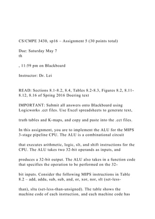
- 6. use of the Barrel Shifter and not the slices. Since the TS output is driving the gate of a tri-state buffer, when it equals 1, then the R output is disabled. Hence, the TS output needs to be Active Low, which you can specify in the PLA implementation. The following figures show you how to connect the PLAs to the input and output ports of each slice. You must create separate device symbols for Slice 0, Slice, and Slice MSB, packaging the PLAs and input/output ports. Slice 0 PLA (for bit 0): func5 func4 func3 func2 func1 func0 A B slt funcfunc P G
- 7. R In0 In1 In2 In3 In4 In5 In6 In7 In8 Out0 Out1 Out2 Out3 alu_plaslice0 CS/CMPE 3430, sp16 – Assignment 5 (30 points total) Due: Saturday May 7 th , 11:59 pm on Blackboard Instructor: Dr. Lei Slice PLA (for bits 1-30): Slice MSB PLA (for bit 31):
- 8. A spreadsheet called “ALU_slice_plas_blank.xlsx” has been posted on Blackboard under Assignment 5 to assist you with creating the three PLAs. For this assignment, you are not required to complete the Barrel Shifter (Figure 8.16), but it is strongly recommended that you complete the Barrel Shifter in order to not have to redo the overall ALU device symbol in the next assignment. If the instruction involves a shift operation (i.e. sll, srl, sra, sllv, srlv, and srav), then the Barrel Shifter output is used. If the instruction involves arithmetic, logic, or slt operations, then the slices output is used. The TS output of the PLAs in each slice, along with the 32-bit tri-state buffer in the Barrel Shifter, work together such that the Barrel Shifter output and the slices output do not conflict with each other. Once you finish implementing the Slices, CLUs, and Barrel Shifter (if you choose to do so in this assignment), package everything into a top-level ALU device symbol. See next page for instructions regarding deliverables for the assignment. funcfunc
- 11. CS/CMPE 3430, sp16 – Assignment 5 (30 points total) Due: Saturday May 7 th , 11:59 pm on Blackboard Instructor: Dr. Lei Deliverables: Submit on a Logicworks file your ALU device symbol, along with an attached test circuit with Hex Keyboards and Displays demonstrating the operation of the add, addu, sub, sub, and, or, xor, nor, slt, sltu instructions. For each instruction, write the 32-bit Hex outputs (in the same logicworks file) of each instruction for the following 32- bit inputs: 32-bit A input: 0x5A5A5A5A 32-bit B input: 0x6B6B6B6B The figure below shows an example of what your submission should look like. The function code is set to 0x2A, which performs the slt instruction of the two inputs. The inputs are set to 0x5A5A5A5A and 0x6B6B6B6B. As a sanity check, your inputs and outputs for the slt instruction should at least match the ones in the figure. Note that the slt output in
- 12. this example is 1, since the 32-bit A31..0 input is less than the 32-bit B31..0 input. A 0 A 1 A 2 A 3 A 4 A 5 A 6 A 7 A 8 A 9 A
- 34. 1 5Title of PaperStudent NameCourse/Number Due Date Faculty Name Title of Paper Triple click your mouse anywhere in this paragraph to replace this text with your introduction. Overview of Organization Triple click your mouse anywhere in this paragraph to replace this text with the overview of the organization. Description of Product/Service Triple click your mouse anywhere in this paragraph to replace this text with the description of your product or service. SWOT Analysis Strengths (Internal) Weaknesses (Internal) Opportunities (External) Threats (External) . Competitive Analysis Triple click your mouse anywhere in this paragraph to replace this text with the description of your competitive analysis.
- 35. Current company’s strengths and weaknesses Potential Competitor’s strengths and weaknesses Competitive Rival’s strengths and weaknesses Target Market Product Place Promotion Price Competitive Barriers Likely responses Target Market Segments Triple click your mouse anywhere in this paragraph to replace this text with the description of your target market.
- 36. Demographic Replace this text with demographic information. Psychographic Replace this text with psychographic information. Geographic Replace this text with geographic information. Behavioral Factors Replace this text with behavioral factors information. Positioning Statement Triple click your mouse anywhere in this paragraph to replace this text with your positioning statement. Conclusion Triple click your mouse anywhere in this paragraph to replace this text with your conclusion. References This is a hanging indent. To keep the hanging indent format, triple click your mouse on this line of text and replace the information with your reference entry. You can use the Reference and Citation Examples (Center for Writing Excellence>Tutorials and Guides>Reference and Citation Examples) to help format your source information into a reference entry. The reference page always begins on the top of the next page after the conclusion. Sheet1ALU-CLU Slices PLA truth tablesInstructor: Prof. LeiSlices 1-30PLA inputsPLA
- 37. outputsIn8In7In6In5In4In3In2In1In0Out3Out2Out1Out0Instruct ionfunc5func4func3func2func1func0ABCTSPGRTS mintermsP mintermsG mintermsR mintermsadd100000000100010000000010000000110011000000 10110110000001111001000001001101100000101110010000011 011101000001111111addu1000010001000100001001100110000 10101101100001011110010000110011011000011011100100001 11011101000011111111sub100010000110100010001110001001 01100010011110001010011110001010111000101101110001011 111subu1000110001100011001110001101011000110111100011 1001100011101110001111011000111111and1001000001010010 00011010010001010100100011101001001001010010010110100 1001101110010011111or10010100010100101001110010101011 10010101111001011001100101101110010111011001011111xor 10011000011001100011100110010110011001111001101001100 110101110011011011001101111nor10011100011001110011100 11101011001110111100111100110011110111001111101100111 1111slt10101000011010100011sub101010010110101001111010 101001101010101110101011011010101111sltu10101100011010 110011sub10101101011010110111101011100110101110111010 1111011010111111Slice MSBPLA inputsPLA outputsIn8In7In6In5In4In3In2In1In0Out5Out4Out3Out2Out1Ou t0Instructionfunc5func4func3func2func1func0ABCTSOvsltPGR TS mintermsOv mintermsslt mintermsP mintermsG mintermsR mintermsadd10000000010samw as prev1000000011110000001010100000011110000010011000001 01110000011011000001111addu10000100011000010011100001 01011000010111100001100110000110111000011101100001111 1sub1000100001010001000110100010010101000100111100010 1001100010101110001011011000101111subu100011000110001 10011100011010110001101111000111001100011101110001111 011000111111and10010000011001000011100100010110010001 111001001001100100101110010011011001001111or100101000 11001010011100101010110010101111001011001100101101110 010111011001011111xor10011000011001100011100110010110 011001111001101001100110101110011011011001101111nor10
- 38. 01110001100111001110011101011001110111100111100110011 1101110011111011001111111slt10101000011010100011101010 01010101010011110101010011010101011101010110110101011 11sltu101011000110101100111010110101101011011110101110 01101011101110101111011010111111Slice 0PLA InputsPLA outputsIn8In7In6In5In4In3In2In1In0Out3Out2Out1Out0Instruct ionfunc5func4func3func2func1func0ABsltTSPGRTS mintermsP mintermsG mintermsR mintermsadd100000000100010000000110001000000101101100 0000111101a+B1000001001101a1000001011101100000110111 01000001111110addu10000100010001000010011000100001010 11011000010111101100001100110110000110111011000011101 1101000011111110sub1000100001100100010001110001001011 0001001111000101001100010101110001011011000101111subu 10001100011000110011100011010110001101111000111001100 011101110001111011000111111and10010000011001000011100 10001011001000111100100100110010010111001001101100100 1111or10010100010100101001101001010101010010101110100 10110010100101101101001011101110010111111xor100110000 11001100011100110010110011001111001101001100110101110 011011011001101111nor10011100011001110011100111010110 011101111001111001100111101110011111011001111111slt101 01000010101010001111010100101010101001111101010100101 01010101111010101101010101011111sltu101011000110101100 11101011010110101101111010111001101011101110101111011 010111111 Sheet2 Sheet3