
Recommended
Recommended
More Related Content
What's hot
What's hot (20)
Similar to Sustainable EV Motor Design
Similar to Sustainable EV Motor Design (20)
Sustainable EV Motor Design
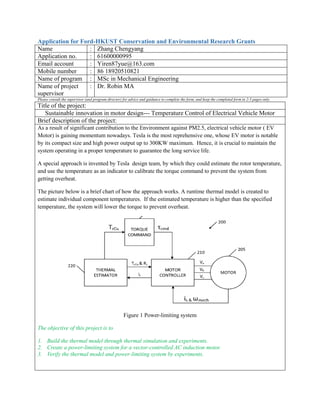
- 1. Application for Ford-HKUST Conservation and Environmental Research Grants Name : Zhang Chengyang Application no. : 61600000995 Email account : Yiren87yue@163.com Mobile number : 86 18920510821 Name of program : MSc in Mechanical Engineering Name of project supervisor : Dr. Robin MA Please consult the supervisor (and program director) for advice and guidance to complete the form, and keep the completed form in 2-3 pages only. Title of the project: Sustainable innovation in motor design--- Temperature Control of Electrical Vehicle Motor Brief description of the project: As a result of significant contribution to the Environment against PM2.5, electrical vehicle motor ( EV Motor) is gaining momentum nowadays. Tesla is the most reprehensive one, whose EV motor is notable by its compact size and high power output up to 300KW maximum. Hence, it is crucial to maintain the system operating in a proper temperature to guarantee the long service life. A special approach is invented by Tesla design team, by which they could estimate the rotor temperature, and use the temperature as an indicator to calibrate the torque command to prevent the system from getting overheat. The picture below is a brief chart of how the approach works. A runtime thermal model is created to estimate individual component temperatures. If the estimated temperature is higher than the specified temperature, the system will lower the torque to prevent overheat. Figure 1 Power-limiting system The objective of this project is to 1. Build the thermal model through thermal simulation and experiments. 2. Create a power-limiting system for a vector-controlled AC induction motor. 3. Verify the thermal model and power-limiting system by experiments.
- 2. 1. Build the runtime thermal model through thermal simulation and experiments. The thermal model is built according to the following procedures: 1) Identify the crucial components of the motor for temperature control. For example --- Bearings, comparing to the components such as shaft, magnetic steel, bars/aluminum of an AC induction squirrel cage rotors, the operating temperature of bearing is much lower. 2) Establish thermal model of the system to estimate the temperature of crucial parts. It is hard to directly measure the temperature of crucial parts. And it would be too complicated to establish thermal model directly based on the motor. If a proxy which could be measured easily and use this to establish the thermal model. The task would be much easier. In this project, we intend to find a proxy. By using the proxy as reference, a computer simulation of the thermal dynamic of the rotor is carried out to estimate the temperature of the crucial components. 3) Figure out the temperature relationships between the torque and the temperature of crucial parts---- Torque & Temperature chart. 4) Using the torque & Temperature chart to calibrate the torque. 2. Create a power-limiting system for a vector-controlled AC induction motor. Please refer to figure 1 in Page 1---- power-limiting system. 1) Thermal protection --- to determining a runtime estimate for a temperature of crucial parts of motor. 2) Torque command --- to generate a torque command. 3) Motor controller--- to generate motor control signal for the vector-controlled AC induction motor responsive to the torque command. 3. Verify the thermal model and power-limiting system by experiments. 1) Experiment system chart: Figure 2 Experiment system 2) Fan load. A fan with 4 blades. The fan load has the similar property of vehicle, whose load is proportional with the v3. 3) Motor. Triple phase asynchronous motor, 1.5KW. 4) Throttle. An analog input signal, represent the throttle of vehicle. 5) HIM. Display the estimated temperature, actual temperature, power, frequency, torque, etc. 6) KPI i. The accuracy of the estimated temperature. ii. The experiment should be able to show two different control modes, with and without
- 3. power-limiting control. Scope and workload (3 credits from Sept to Dec or 6 credits from Sept to Apr/May): The scope of the project is Sustainability study. The work load is 6 credits from Sept to May. Figure 3. Timetable of the project Format of output (eg. A final report, a presentation, and/or demonstration): A final report, a presentation (or demonstration) and a journal paper. Methodology and related information: Detailed financial budget (maximum budget is around HK$19,890): Details HK$ Equipment a. Thermocouples( Pt100) *6 800 b. PLC AB 1769-L18ER-BB1B 6,900 c. PLC power supply 1769-PA2 1,050 d. PLC right end cap 1769-ECR 100 e. Analog Input Module 1769-IF8 2,600 e. Frequency converter AB Power Flex70 1.5KW 2,340 f. Motor 1KW*2 1,200 g. Other electrical components 500 Outsourcing Fee a. Test shelf 800 b. Machining Fee 1,600 c. Fan 1,500 Travelling/Transportation a. Deliver fee 500 Total budget : 19,890 References [1] Andrew David Baglino, Greg Grant Solbertg, Yifan Tang. Rotor temperature estimation and motor control torque limiting for vector-controlled AC induction motors. United States Patent Application Publication, US 2012/0007532 A1; Mar.21,2013 [2] Shibo Chen, Electric Drive and Automation Control System 3rd Edition, July,2003.