1. Optimization of an Electrostatic Bumper Painting Process
Presented by Brian Anichowski, Yucheng Guo, Steph Keller, John Menke, and Miles Reagans
Advised by Dr. Jose Castro, Dr. Rachmat Mulyana, Robert Rhoads, Dr. Cliff Whitfield, and Jake Allenstein
Multidisciplinary Capstone, Department of Engineering Education, The Ohio State University
Introduction
Objectives
Process Introduction
Baseline Testing Experimental Testing
Future Work or Acknowledgements??
• Typical painting processes involve spraying paint particles at the target,
and often allows for significant amount of overspray (the paint goes past
the part and doesn’t adhere to the intended surface).
• One method to reduce the overspray
is by electrostatically charging the
part and the paint. By negatively
charging the paint particles, and
grounding the part, the paint is
actively drawn to the surface of the
part.
• Negatively charging the paint is easy, however substantial difficulties exist
when attempting to ground the part. In particular, bumpers prove to be
extremely difficult because they are plastic, and therefore non-conductive.
• Ensure a consistent, proper grounding of the bumper.
• Ensure a consistent, proper checking of the grounding of the bumper
• Experimentally highlight key areas of focus within the grounding process.
• The bumper has a conductive primer
applied using conventional (non-
electrostatic) methods.
• Bumpers are loaded onto a metal carrier
which runs along a grounded carrier track
through the painting process.
• The bumpers are electrically connected to
the carrier through the use of clips (fixed
to the carrier) and conductive foil tape.
• Performed testing to isolate the problem areas of the process.
• Focused on...
1. Internal Carrier Resistance(s)
2. Paint Buildup
3. Ground Check System Accuracy
• The bumper is then ran through a
insulation checker to measure the
resistance to ground.
• If the bumper passes the resistance
check, it is sent through the paint
and clearcoat process before being
installed into the vehicle.
• First, the team measured the resistance
between the carrier and ground (see right)
with clean clips, to remove the impact of
paint buildup.
• Second, the team measured the same
resistance, but did NOT clean the clips.
• Internal carrier resistance was found to be negligible with respect to the
same tests with dirty clips ( ).
• The team then looked at the accuracy of the ground check system by
manually duplicating measurements with an ohmmeter.
carrier paintR R
• These tests showed the team that the ground check system was not working
as intended and was not accurately measuring the resistance to ground.
Experimental Testing
• From baseline testing, along with other areas of interest from the team, it
was decided to focus on four main topics:
1. Redesigned Carrier Clip
2. Circuit Verification
3. Flat Plate Primer Thickness Testing
4. Surface Contour Testing
Clip Redesign
• Team wanted to focus on mitigating paint
buildup
• One side of the carrier had an uncovered clip,
one side had a covered clip.
• (Qualitative) Results showed a decrease in the
paint on the contact surface with the covered
clip through 200 cycles.
Circuit Verification
• Testing was performed by introducing known resistance values (resistors)
into the circuit and recording the output from the check circuit system.
• The new configuration shows a 1:1 correlation between the actual and
measured resistance and a marked improvement from the original results.
Flat Plate Testing
• The team wanted to correlate primer thickness to paint thickness, so
different plates from the bumper material were primed them at different
thicknesses, then ran them through the bumper paint line.
• Little correlation can be seen here as primer thickness differed, although
the team believes more testing is required to validate results.
Contour Testing
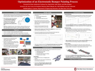
• The team wanted to investigate the impact the surface profile of the
bumper had on primer thickness. Since primer thickness has been shown
to have an affect on resistance, it was assumed to be true here.
• As can be seen, distance from the grounding locations (red x’s) increases
the surface resistance. As well, adding a third grounding location reduced
the peak surface resistance by almost 60%.