
Recommended
More Related Content
What's hot
What's hot (20)
Similar to power 6210.pdf
Similar to power 6210.pdf (20)
Recently uploaded
Recently uploaded (20)
power 6210.pdf
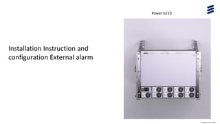
- 1. Power 6210 Prepared by Karim Kheder Installation Instruction and configuration External alarm
- 2. Power 6210 The Power 6210 DC Power System supplies -48 V DC to Ericsson Radio System and auxiliary equipment. Flexible hardware design The Power Unit can be installed on top of battery racks or mounted on walls. The Power 6210 is flexible to adapt to small as well as large power and battery backup requirements. Selection of two sizes of battery racks is available • A Compact rack that can hold up to 48V/400Ah battery capacity. • A higher capacity rack that can hold up to 48V/840 Ah battery capacity. • Several battery racks can be parallel connected to achieve even higher battery capacity. Optional 19” equipment installation rail kits are available to provide 8HU mounting space for auxiliary 19” equipment in the upper sections of the battery racks. Supervision and Control The Power 6210 system controller features an LCD display and key pad for quick access to system information at the site and can also be accessed remotely through the cabinet controller. Power 6210 is though the cabinet controller optionally integrated to OSS/ENM or ESCM Prepared by Karim Kheder
- 3. Allocations Power 6210 must be mounted on the wall in PO 07 with MECHANICS/Power on Wall Set SXK1092010/1 Tool Product Name Wire stripper 0.2–30.0 mm Side cutter Slotted head screwdriver, D3, D6, and D8 Torque screwdriver • 0.5–6.0 Nm Bits • Phillips head PH1 • Phillips head PH2 • Phillips head PH3 Torque wrench Sockets • 10 mm • 13 mm • 16 mm Hammer drill with depth restrictor, minimum depth 300 mm Ear protectors Eye protectors Prepared by Karim Kheder
- 4. Cable Routing This section describes the cable routing options of Power 6210. A maximum of four battery racks can be connected to the power rack when the power rack is wall mounted. Meanwhile, power calculation must be completed to ensure the current does not exceed battery CB rating. The options below highlight the connections for a single battery rack, two battery racks, and four battery racks. The option of three battery racks can also be utilized and connected in the same design as four battery racks. The extension to three or four battery racks is only applicable to the capacity rack. Prepared by Karim Kheder
- 5. Grounding Cable Connections The battery rack and power rack must be grounded to protect them from overvoltage and lightning strikes. Routing: From Routing: To Cable Type Dimensions (mm) Product No. Battery rack Site Ground Cable 1900 RPM777573/01900 Prepared by Karim Kheder
- 6. Connect Incoming AC Power Cables This section describes how the AC main power is installed. Power Rack 8 kW ST have single-route AC Input. Install the L/ N/ grounding cable/cable into the interface and tighten the screw. Use a cable tie to secure the power cables to the frame above the AC input interfaces. Prepared by Karim Kheder
- 7. Install Rectifiers Power Rack 8 kW ST supports up to four rectifiers (In PO 07 it’s ordered with 3 Rectifier 3.0 kW 95.5% BML901407/1 Prepared by Karim Kheder
- 8. Install 19-Inch Unit in Battery Rack Make sure that four screws and cage nuts are available to secure the unit on the rack. Prepared by Karim Kheder
- 9. AGM Battery Strings – Power Rack Pos Routing: From Routing: To Cable Type Dimensions (mm) Product No. 1 Battery string 1 Battery circuit breaker Battery cable 2800 RPM777573/02800 Battery string 2 2400 RPM777573/02400 Battery string 3 2400 RPM777573/02400 Battery string 4 2400 RPM777573/02400 2 Battery string 1 0 V connector block Battery cable 2800 RPM777573/02800 Battery string 2 2400 RPM777573/02400 Battery string 3 2400 RPM777573/02400 Battery string 4 2400 RPM777573/02400 Prepared by Karim Kheder
- 10. Power Shelf – Indoor DC Equipment Pos. Routing: From Routing: To Cable Type Product No. 1 Battery strings Battery circuit breaker Battery power RPM777573 2 Battery strings 0 V connector block Battery power RPM777573 3 0 V connector block Indoor DC equipment Power cable RPM 777 554/01000 4 Battery circuit breaker Indoor DC equipment Power cable RPM 777 554/01000 Prepared by Karim Kheder
- 11. Battery Temperature Sensor – Power Rack Pos. Routing: From Routing: To Cable Type Dimensio ns (mm) Product No. 1 Battery block 1 Power rack Power cable 1000 KET10970/2 2 Battery block 1 (Battery Backup System) Power rack Power cable 1000 KET10970/2 Prepared by Karim Kheder
- 12. SCU – Power Rack Pos. Routing: From Routing: To Cable Type Product No. 1 SCU : serial port Power rack: communication cable connector Communication cable Pre-installed in the power rack 2 SCU : −48 V DC power port Power rack: DC load circuit breaker Power cable RPM777554/01000 3 SCU : −48 V DC power port Power rack: 0 V connector block Power cable RPM777554/01000 Prepared by Karim Kheder
- 13. SCU– SAU Pos. Routing: From Routing: To Cable Type Product No. 1 SCU : SAU port SAU: SAU port Alarm cable RPM777143/02000 Prepared by Karim Kheder
- 14. Configuration Externals Alarm : Connectivity Cable Relay “1” & “2“ & “3” & “4” to OVP
- 15. Configuration Externals Alarm on M530B Setting Dry Contact Alarm Types : A certain type of alarm can be output by a certain dry contact through setting the parameter of the ‘output relay’ in the alarm type. Once the alarm event occurs, the corresponding dry contact will act and generate an alarm.
- 16. Configuration Externals Alarm Password level Operation authority Default password Engineer level All the user’s authorities, plus operation authorities such as changing system type and changing energy saving parameter 2 Press Entre log in with password “2” Press Entre and chose setting Press Entre and chose Alarm Level
- 17. Relay Configuration Alarm Description Alarm Severity Relay Nbr # 1 Main Power Failure (Naming DU side MAIN FAILLURE PWR 6210) Major Relay 01 M and NC port # 2 Load Fuse Alarm (Naming DU side CB DC FAILLURE PWR 6210) Critical Relay 02 M and NC port # 3 Battery Fuse Alarm (Naming DU side BAT CB ALARM PWR 6210) Critical Relay 02 M and NC port # 4 Multi-Rectifier Alarm (Naming DU side MULT RECT ALARM PWR 6210) Major Relay 03 M and NC port # 5 Rectifier Comm Fail (Naming DU side RECT ALARM PWR 6210) Critical Relay 03 M and NC port # 6 Temp 1 High Temperature sensor 1 (Naming DU side TEMP SENSOR /H &VH TEMP PWR 6210) Major Relay 04 M and NC port # 7 Temp 2 High Temperature sensor 2 (Naming DU side TEMP SENSOR /H &VH TEMP PWR 6210) Major Relay 04 M and NC port
- 18. Configuration Externals Alarm : # 1 Main Power Failure (Naming DU side MAIN FAILLURE PWR 6210) Major Relay 01 M and NC port
- 19. Configuration Externals Alarm : # 2 Load Fuse Alarm (Naming DU side CB DC FAILLURE PWR 6210) Critical Relay 02 M and NC port # 3 Battery Fuse Alarm (Naming DU side BAT CB ALARM PWR 6210) Critical Relay 02 M and NC port
- 20. Configuration Externals Alarm : # 4 Multi-Rectifier Alarm (Naming DU side MULT RECT ALARM PWR 6210) Major Relay 03 M and NC port # 5 Rectifier Comm Fail (Naming DU side RECT ALARM PWR 6210) Critical Relay 03 M and NC port
- 21. Configuration Externals Alarm : # 6 Temp 1 High Temperature sensor 1 (Naming DU side TEMP SENSOR /H &VH TEMP PWR 6210) Major Relay 04 M and NC port # 7 Temp 2 High Temperature sensor 2 (Naming DU side TEMP SENSOR /H &VH TEMP PWR 6210) Major Relay 04 M and NC port Two temperature sensors are configured by default. If the third temperature sensor is installed, set Temp3 to Batt Temp.
- 22. Configuration Externals Alarm : Two temperature sensors are configured by default. If the third temperature sensor is installed, set Temp3 to Batt Temp. On Setting Chose Bat Setting Entre Chose Temp Comp Chose Temp 3 Set Temp3 to Batt Temp