
Recommended
Recommended
More Related Content
Similar to ENG1002 Design project - Client Brief Version 2.0 1 © .docx
Similar to ENG1002 Design project - Client Brief Version 2.0 1 © .docx (20)
More from YASHU40
More from YASHU40 (20)
Recently uploaded
Recently uploaded (20)
ENG1002 Design project - Client Brief Version 2.0 1 © .docx
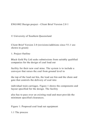
- 1. ENG1002 Design project - Client Brief Version 2.0 1 © University of Southern Queensland Client Brief Version 2.0 (revisions/additions since V1.1 are shown in green) 1. Project Outline Black Gold Pty Ltd seeks submissions from suitably qualified companies for the design of coal load out facility for their new coal mine. The system is to include a conveyor that raises the coal from ground level to the top of the load out bin, the load out bin and the chute and gate that controls the delivery of coal into individual train carriages. Figure 1 shows the components and layout specified for the design. The facility also has to pass over an existing road and must provide the minimum specified clearances. Figure 1: Proposed coal load out equipment 1.1 The process
- 2. Coal direct from the Black Gold mine arrives at the load out bin via a feed conveyor and is transferred to the lift conveyor and carried to the top of the circular load out bin. A short chute (1 metre in height) and gate at the base of the load out bin controls the flow of coal into each train wagon. The load out bin is comprised of a conical section A, a cylindrical section B and a truncated conical section C. Several design requirements will be specified by Black Gold Pty Ltd for the total storage volume of the load out bin, a range of mass flow rates at which the train wagons can be loaded and the types of equipment that can be selected for the design. Students please note – read the IMPORTANT NOTES on the last page of this document and the comments regarding the completion of individual assignments in italics Plan View Side View Elevation Coal flow
- 3. Load out bin supported in square frame of steel road Feed conveyor 6m H D = 5m minimum Load- out bin rail line 8m Minimum clearance 6m Drawing not to scale
- 4. chute diameter d 1m high h2 h 1 h 3 5m Steel support 3m Lift conveyor length L A B C x = 3m minimum x D
- 5. Lift conveyor variable length X conveyor angle theta 1 θ 1 h C the density of coal is 810 kg/m 3 cone angle theta 1 θ1 10 to 30 degrees theta 2 = 45 degrees 2 ENG1002 – Introduction to Engineering and Spatial Science Applications
- 6. 2. Design Sections The project has been divided into three design sections, plus a costing, to ensure that the requirements of the project are clear. Each section of the design is to be defined by the set of design parameters, listed in bold. Any company submitting a design proposal must use these variables names to identify the parameters. Each design section requires a technical analysis which must be summarised in the design proposal. The Design Sections are: 1. The dimensions of the load out bin and other equipment - the diameter of the load out bin (in m) - the total height of the load out bin and frame (in m) - the heights of each section of the load out bin (in m) ) - cone and conveyor angle (in degrees) - the volume of the load out bin (in m 3 ) – the distance from the load out bin to the road (in m) (X and L now listed in section 2) - the clearance over the road (in m)
- 7. - the maximum mass of coal in the load out bin (in tonnes) 2. The dimensions of the conveyor and related parameters (this section may be used for the Presentation assessment) (the width of the conveyor belt is not variable – see table 2) – the lengths which define the conveyor (in m) (now to be stated here) – the maximum speed of the conveyor (in m/s) - the maximum Mass Flow rate of the Conveyor (in kg/s) – the power output required of the conveyor motor (in W) -n - the Motor size selected to drive the conveyor 3. The gate and loading control and related parameters (this section may be used for the Presentation assessment) - the diameter of the chute (in m) - the cross-sectional area of the chute (in m 2 ) - the Mass Flow rate into the Wagons (in kg/s) – the time required to fill each wagon (in seconds) – the time interval between each wagon (in seconds)
- 8. – the required speed of the train (in kph) 4. The budget and costs of the components of the system including the steel frame and support (students are now to ignore the requirements of the steel frame) - the surface area of the load out bin (in m 2 ) – the cost of the load out bin (to the nearest $) – the cost of the conveyor excluding motor (to the nearest $) – the cost of the conveyor motor (to the nearest $) – the total cost of the conveyor (to the nearest $) 2.1 Design Goals The design goals for the project are to: G1. maximise the storage volume of the load out bin G2. maximise the rate at which coal can be loaded into the train wagons G3. stay within the allocated budget ENG1002 Design project - Client Brief Version 2.0 3
- 9. © University of Southern Queensland 3. Specification of Requirements 3.1 Requirements The following requirements must be met: R1. The facility must be capable of loading at least 2000 tonne (metric) of coal per hour into the wagons. The train wagons hold a maximum of 100 tonne each (moved to constraints) R2. A minimum of 300 tonne of coal (enough to load 3 train wagons) must be stored in the load out bin, to allow for brief stoppages of the conveyor. R3. The conveyor must be capable of delivering coal to the load out bin at 110% of the rate at which the wagons can be filled. This will allow the level of coal in the load out bin to be replenished after brief stoppages of the conveyor, while still loading wagons. 3.2 Scope The technical analysis and design work required for this project only requires the selection of components from those provided and the specification of values for the parameters listed for each Design Section. In particular, aspects of the project that are
- 10. outside the scope of the design include: or materials not specified in versions of this brief 3.3 Constraints (constraints have been numbered) The following constraints apply: C1. A maximum budget of $82,500 C2. The maximum height (H) for the design is not to exceed 18m. C3. The load-out bin must be cylindrical in shape, with conical ends. C4. The minimum height for the cylindrical section of the load out bin is to be 1m. C5. The minimum diameter of the load-out bin is to be 5m. C6. The angle (theta 1) of the conveyor must be between 10 and 30 degrees C7. The train wagons hold a maximum of 100 tonne each 3.4 Assumptions The following simplifying assumptions have been made: -out bin is usable, but not the chute. of the walls of the silos and load-out bin can be ignored in volume calculations. how this is achieved is beyond the
- 11. scope of this design. variations in moisture content is to be ignored. considered. ignored 4 ENG1002 – Introduction to Engineering and Spatial Science Applications 4.0 Technical Information (students - all this information is new, except rho) 4.1 Load Out Bin, chute and gate control Table 1: Technical Information relevant to the load out bin Quantity variable value unit Density of coal (same as in V1.1) ρ (rho) 810 kg/m 3 Cost of load-out bin (per m 2 of surface area) cB 100 $/m
- 12. 2 Length of wagon (wagon to wagon) Lw 12 m Useful length of opening on the wagon Lo 9 m Width of opening on the wagon w 1.5 m Coal is loaded into the train wagons as the train moves continually at a constant speed S (in kph) beneath the chute. The gate on the chute is to be opened while the opening in the wagon is under the centre of the chute. You are to assume- - that the useful length of opening Lo takes into account the position of the wagon with respect to the chute, such that no coal is lost over the end of the wagon. - the gate opens and closes instantaneously and that the coal flow into the wagon starts and stops instantaneously (ignore any delays including the time for coal to fall through the 1m deep chute) - the width of the opening on the coal wagon (w) is 1.5 m Figure 2: Proposed coal load – train loading side view The mass flow rate into the wagon from the chute is given by:
- 13. √ where MFw is the mass flow rate of coal (in kg/s), a is the cross-sectional area of the chute (in m 2 ), d is the diameter of the chute (in m) and g is gravitational acceleration constant (in m/s 2 ). 12m LO Load- out bin chute diameter d Side View 2 Elevation useful length of opening Length of wagon Lw (wagon to wagon)
- 14. w width of opening motion of train ENG1002 Design project - Client Brief Version 2.0 5 © University of Southern Queensland 4.2 Conveyor Black Gold already operates and maintains other conveyor equipment, so to avoid a requirement to hold additional spare parts, you are required to select conveyor components from those listed below. Table 2: Technical Information relevant to the conveyor Quantity variable value or equation unit Load Factor (accounts for conveyor friction) LF 0.2 none Conveyor belt width W 0.8 m Conveyor cross sectional area (of coal on conveyor) Ac = π/12 * W 2
- 15. m 2 Cost of conveyor (per linear metre) cC 700 $/m The output power required from the motor to drive the conveyor and raise the coal in height is given by: ( ) where P is power (in W), MFc is the mass flow rate of coal (in kg/s), Δh is the change in height (in m), g is gravitational acceleration constant (in m/s 2 ), theta1 is the angle of the conveyor (in radians) and LF is the Load Factor (dimensionless). Table 3: Conveyor motor options – (costs include motor control equipment) Motor Size Output Power (kW) Cost ($) M-5 50 5000 M-8 80 8000 M-10 100 10000 M-12 125 12500
- 16. 6 ENG1002 – Introduction to Engineering and Spatial Science Applications Important note to students The sections listed above are to be used to subdivide the analysis and design process and identify the sections you are to use for your Technical Analysis, Presentation and Design Proposal assessments, as detailed in the requirements of each assessment. IMPORTANT: This is a closed design problem where all information required to complete the technical analysis, calculations and evaluation of possible solutions will be available in the Client Brief, your text books or other provided assignment material. The problem presented is a simplified version of a real design problem, so the fine details of the components of the proposed system are ignored. If you find yourself seeking information beyond that provided in the Client Brief,
- 17. your text books or other assignment material then you are probably over thinking the problem. The three assessments using this problem are able to be completed using just the engineering fundamentals you are studying, supported by other course material and tools like the spreadsheet. There is no need to research commercial equipment. For the Technical Analysis assessment all students must complete a technical analysis and prepare a short technical report on Design Section 1 (only) of the project. Your memorandum to a (pretend) colleague is to request a technical analysis and short technical report on one of either section 2 or 3. For the Presentation assessment each student will select design section 2 or 3 of the project on which to complete a technical analysis and prepare a short oral presentation. [This can be the same as the section your request of your colleague in your memo – that is not important.] You are to present a summarised technical analysis of that section of the
- 18. design and how it depends-on / influences any other section of the design. The presentation is to be prepared and delivered as if to other colleagues in your company who are working with you on the larger project. For the Design Proposal assessment students are expected to complete the technical analysis for the whole project, model the design on a spreadsheet, evaluate some alternatives within the design and select a specific design solution to recommend in their report. The recommendation must clearly specify all of the parameters listed in the design sections in bold, as they define each section of the design. Students should note there is more than one correct answer to this problem, as several possible solutions will meet the requirements of the design. Furthermore - a technical analysis of a single design section ALONE is unlikely to identify a set of design parameters that results in the final project design, as the sections are somewhat dependent on each other. Hence when you complete a technical
- 19. analysis on a single section of the design you are not looking for a specific ‘answer’ to that section. Your analysis should show the relationships between the parameters (eg. D, H, etc) within a section and possibly with those in other sections of the design. This analysis will allow you to eliminate some of the alternative equipment suggested (when it is evident it cannot do the job), or you may be able to reduce the range of values for some parameters which offer a possible solution. Technical Analysis Page 2 _____________________________________________________ _________________________ Technical Analysis of Proposed Coal Load Out Conveyor System _____________________________________________________ _________________________ Prepared by: September, 2014.
- 20. Introduction This section presents a technical report of the coal load out bin and other equipment that are presented in figure 1. Among the issues to be addressed in this report are the ideal dimensions of D, H, h1-h3, θ1, V, X,L and x, hc and M. Trigonometry will be vital in meeting this objective (Riley, Hobson, & Bence, 2006). These dimensions are explained below. · D the diameter of the load out bin (in m) · H the total height of the load out bin and frame (in m) · h1to h3 the heights of each section of the load out bin (in m) · θ1 (theta 1) cone and conveyor angle (in degrees) · V the volume of the load out bin (in m3) · X, L and x lengths which define the conveyor (in m) · hC the clearance over the road (in m) · M the maximum mass of coal in the load out bin (in tonnes) Figure 1: Proposed coal load out equipment To begin with, D will be assumed to be at minimal value, which has already been stated as being 8m. The selection of D as 8m is because this falls within the allowable minimum and maximum limits, making it acceptable in terms of size and volume that it will carry. The selection of this dimension will affect the length of x as presented below. If D is 8m, this will mean that: · The radius of section B in figure 1 will be , making it · x = · = 8 – 4 · = 4 m Other dimensions for x and D, depending on the selected size of D are presented in the table below Table 1: Values of x and D X D 3.00 10 3.50
- 21. 9 4.00 8 4.50 7 5.00 6 5.50 5 The values above have been established from the expression In order to obtain the value of H, trigonometric equations will be used to relate these distances (Bolton & Bolton, 2012). Assuming that the load out bin is perfectly vertical and the surface on which it stands is horizontal, the intersection between H and X will be at a right angle. Therefore, the relation between H and X will be as follows: Where tan 1 = Therefore, H = X* This is because the angle ay the top of load out bin is the same as the angle of intersection between the lift conveyor and the horizontal surface. From the above, L will be expressed as In order to determine h1-h3, it will be represented as a difference between H and (5m + d). Where d, as mentioned in figure 1, is the chute diameter, which is 1m. This will be represented in equation form as: = X* But d + 1m X* The cone conveyor angle θ1 (theta 1), as has already been mentioned earlier, will be obtained by the formula below: Tan 1 = Therefore, θ1 = tan-1 V, which is the volume of the load out bin, will be calculated by
- 22. calculating the volumes of sections A, B and C in figure 1 separately. The volume of A, which will be conical, will be determined by the formula () (Riley, Hobson, & Bence, 2006). Figure 2: Volume of a conical structure Source: Riley, Hobson and Bence (2006) Applying the above formula, the volume of A will be (). This can be presented as: VA = () Section B is cylindrical and thus, its volume will be estimated by the formula Thus, VB = Finally, the volume of section C, being conical too, will be estimated by the formula () Thus, VC = () The total volume of the whole load out bin will therefore be VA + VB + VC VA + VB + VC = () + + () = () + + ()) Thus, V= () + + ()) In order to establish the length of hC as presented in figure 1, trigonometric relations will also be used. Tanθ1= = But tan θ1 = Therefore, And hC = Finally, M which is the maximum mass of the coal in the load out bin will be calculated with the value of D at 10, which results in the minimum value of x. (see table 1). Therefore, applying the formula of V V= () + + ()) Replacing D/2 with 5, the volume will be as follows: V= () + + ()) V=
- 23. = Mass will therefore be V*density, which is 810 kg/m3* However, at maximum volume, θ1 is at 10◦ Therefore, tan θ1= 0.17633 But h1= = 5*0.17633 = 0.8816 m Then, given that θ2= 45◦, h3 = D/2 = 5m V= V=154 + 78.54h2 Mass = 810 (154 + 78.54 h2) = (124740 + 63617.25 h2) kg = (124.74 + 63.617 h2) tonnes Conclusion The expressions that have been presented above provide guidance on how the dimensions of the different elements of section 1 can be obtained. As presented in the equations above, most of the dimensions are affected the value of others. An estimation of the maximum mass that can be supported by the coal bin is essential in guiding the materials that can be used in the provision of support for the entire load. References Bolton, W. & Bolton, W., 2012. Mathematics for Engineering. New Jersey: Routledge. Riley, K.F., Hobson, M.P. & Bence, S.J., 2006. Mathematical Methods for Physics and Engineering: A Comprehensive Guide. Chicago: Cambridge University Press. Requirements Students must prepare and deliver their presentation as if to a group of colleagues within the same company. Student are also required to review 3 other student's presentations. Students are
- 24. to assume their colleagues are familiar with and are working on other sections the same project. Students must treat the assessment as a real engineering presentation. Each student is required to: 1. prepare and present a short (5 to 6 minute) oral presentation on the technical analysis for one section of the design project and explain how it links-with/influences one other section of the design. The section selected as the focus of the presentation must be chosen from either the section 2 or 3 of the design project. It may be the same as the section you requested in your memo or not, this is not important. The presentation must include: a title slide; a professional format; mention of the project and the Client Brief; a diagram clearly identifying the relevant section of the design; a brief technical analysis of the section and any key findings; a clear explanation of how this section links to another; a graph to demonstrate the link between the two sections. Penalties will apply if you exceed 7 minutes.