SlideShare a Scribd company logo
1 of 37
Download to read offline
Activated Sludge Process
The most common suspended growth process
used for municipal wastewater treatment is the
activated sludge process as shown in figure:
Activated Sludge Process Variables
• The main variables of activated sludge process are the
mixing regime, loading rate, and the flow scheme.
• Mixing Regime
• Generally two types of mixing regimes are of major
interest in activated sludge process: plug
flow and complete mixing. In the first one, the regime
is characterized by orderly flow of mixed liquor through
the aeration tank with no element of mixed liquor
overtaking or mixing with any other element. There
may be lateral mixing of mixed liquor but there must be
no mixing along the path of flow.
• In complete mixing, the contents of aeration tank
are well stirred and uniform throughout. Thus, at
steady state, the effluent from the aeration tank has
the same composition as the aeration tank
contents.
• The type of mixing regime is very important as it
affects (1) oxygen transfer requirements in the
aeration tank, (2) susceptibility of biomass to shock
loads, (3) local environmental conditions in the
aeration tank, and (4) the kinetics governing the
treatment process
• Loading Rate
• A loading parameter that has been developed over
the years is the hydraulic retention time (HRT), Ɵ, d
• Ɵ = V
Q
• V= volume of aeration tank, m3, and Q= sewage
inflow, m3/d
• Another empirical loading parameter
is volumetric organic loading which is defined as
the BOD applied per unit volume of aeration
tank, per day.
• A rational loading parameter which has found
wider acceptance and is preferred is specific
substrate utilization rate, q, per day.
q= Q (SO - Se)
V X
• A similar loading parameter is mean cell
residence time or sludge retention
time (SRT), Ɵc, d
• Ɵc = V X
QwXr + (Q-QwXe)
• where SO and Se are influent and effluent organic
matter concentration respectively, measured as
BOD5 (g/m3), X, Xe and Xr are MLSS concentration
in aeration tank, effluent and return sludge
respectively, and Qw= waste activated sludge
rate.
• Under steady state operation the mass of waste
activated sludge is given by
• QwXr = YQ (SO - Se) - kd XV
• where Y= maximum yield coefficient (microbial
mass synthesized / mass of substrate utilized)
and kd = endogenous decay rate (d-1) .
• From the above equation it is seen that
• 1/Ɵc = Yq - kd
• If the value of Se is small as compared SO, q may
also be expressed as Food to Microorganism
ratio, F/M
• F/M = Q(SO- Se) / XV = QSO / XV
• The Ɵc value adopted for design controls the
effluent quality, and settleability and
drainability of biomass, oxygen requirement
and quantity of waste activated sludge.
Main Types of Activated Sludge
Process
• The various types of activated sludge
processes are listed below: 1. Conventional
Activated Sludge Process 2. Tapered Aeration
Process 3. Step Aeration Process 4. Contact
Stabilization Process 5. Complete Mix Process
6. Modified Aeration Process 7. Extended
Aeration Process.
1. Conventional Activated Sludge
Process:
• Fig. below shows a schematic diagram of the
conventional activated sludge process which
consists of an aeration tank, a secondary settling
tank, a sludge return line and excess sludge waste
line. The conventional activated sludge process is
always preceded by primary settling. Thus in this
case the mixture of the settled sewage from the
primary settling tank and the returned activated
sludge from the secondary settling tank is let in at
the head end of the aeration tank and is aerated for
a period of about 6 hours.
• The conventional activated sludge process
employs plug flow regime which is achieved by
using the aeration tank of long and narrow
configuration with length equal to 5 or more
times the width. Because of plug flow regime, the
demand of oxygen by the micro-organisms and
the F/M ratio are the highest at the head end of
the aeration tank and then gradually decreases.
• However, air is supplied in the process at a
uniform rate along the length of the aeration tank
which leads to either oxygen deficiency in the
initial zone or wasteful application of air in the
subsequent reaches.
• The other limitations of the conventional activated
sludge process are:
• (i) There is a lack of operational stability at times of
excessive variations in rate and strength of influent
sewage;
• (ii) Biological upsets are common; and
• (iii) Skilled operation is required.
• In spite of these limitations, for historical reasons,
the conventional activated sludge process is the
most widely used type of the activated sludge
process, and plants upto 300 Mid capacity have
been built in India. The various shortcomings of the
conventional activated sludge process are eliminated
in the other activated sludge processes described
below.
2. Tapered Aeration Process:
• The objective of tapered aeration is to match the
quantity of air supplied to the demand exerted by the
micro-organisms, as the mixed liquor traverses the
aeration tank. At the inlet of the aeration tank where
fresh settled sewage and returned activated sludge
first come in contact, the oxygen demand is very high.
• The diffusers are spaced close together to achieve a
high oxygenation rate and thus satisfy the demand. As
the mixed liquor traverses the aeration tank, synthesis
of new cells occurs, increasing the number of micro-
organisms and decreasing the concentration of
available food. This results in a lower food to micro-
organism (F/M) ratio and a lowering of the oxygen
demand.
• The spacing of diffusers is thus increased towards
the tank outlet to reduce the oxygenation rate.
Thus tapered aeration process involves only a
modification in the arrangement of diffusers in
the aeration tank and the amount of air
consumed as indicated above, and in a strict
sense, it is only a modification of the
conventional activated sludge process.
• The tapered aeration process is widely used
because of the following advantages:
• (i) There is optimal application of air.
• (ii) Due to reduced oxygenation less air is required
which results in reducing the size of the
compressors as well as the initial and operating
costs.
• (iii) Avoidance of over-aeration will inhibit the
growth of nitrifying organisms, which may cause
high oxygen demands.
3. Step Aeration Process:
• The step aeration process is a modification of the
conventional activated sludge process in which
the settled sewage from the primary settling tank
is introduced in the aeration tank at several
points along the length of the aeration tank,
while the returned activated sludge is introduced
at the head end of the aeration tank as shown in
Fig. below:
• The aeration tank is subdivided into four or more
parallel channels through the use of baffles. Each
channel is a separate step, and the several steps are
linked together in series. A typical flow sheet for
this process is shown in Fig. 13.17. The returned
activated sludge enters the first step of the aeration
tank along with a portion of the settled sewage.
• The influent sewage and returned activated
sludge are mixed by the action of diffused or
mechanical aeration, which is constant as the
mixed liquor moves down the aeration tank.
During this period, adsorption, flocculation, and
oxidation of the organic matter take place. The
mixed liquor is withdrawn at the tail end of the
aeration tank and is settled in the secondary
settling tank (or activated sludge settling tank),
and from this tank activated sludge is returned at
the rate of approximately 25 to 50 percent of the
influent sewage flow rate.
ASTP
MLSS: What is MLSS (Mixed Liquor Suspended
Solids) in wastewater treatment?
Mixed Liquor Suspended Solids, or MLSS, is a measure of
the total concentration of solids in an aeration tank, used in
the wastewater treatment process. It is made up of
bacteria, organic substances, and suspended non-
biodegradable materials.
Moreover, MLSS is thought to be a mixture of suspended
particles and influent wastewater, which acts as a
barometer for the system's biomass.
Optimization of MLSS: Good MLSS in
wastewater treatment
Around 1500 mg/L to 5000 mg/L of MLSS is
employed in traditional activated sludge wastewater
treatment facilities. General range for effective
working of aeration tank is 2500 to 3000 mg/L.
For smaller aeration tanks where the treatment level
is constant, higher MLSS concentration is
advantageous. Higher MLSS is indicated by increased
BOD loading, thickening sludge, high flow rates,
insufficient settling times, and nutritional deficiency
in the biomass.
Nevertheless, aeration efficiency may decrease as
MLSS concentration rises. Low MLSS therefore
denotes that the DO concentration is not being
maintained, fewer organisms are surviving, the flow
rate is falling due to the absence of microorganisms,
and both stalked and free-swimming ciliates are
declining.
Trickling Filters
• Trickling filter is an attached growth
process i.e. process in which microorganisms
responsible for treatment are attached to an
inert packing material. Packing material used
in attached growth processes include rock,
gravel, slag, sand, redwood, and a wide range
of plastic and other synthetic materials.
• Process Description
• The wastewater in trickling filter is distributed
over the top area of a vessel containing non-
submerged packing material.
• Air circulation in the void space, by either natural
draft or blowers, provides oxygen for the
microorganisms growing as an attached biofilm.
• During operation, the organic material present in
the wastewater is metabolised by the biomass
attached to the medium. The biological slime
grows in thickness as the organic matter
abstracted from the flowing wastewater is
synthesized into new cellular material.
• The thickness of the aerobic layer is limited by the
depth of penetration of oxygen into the microbial layer.
• The micro-organisms near the medium face enter the
endogenous phase as the substrate is metabolised
before it can reach the micro-organisms near the
medium face as a result of increased thickness of the
slime layer and loose their ability to cling to the media
surface. The liquid then washes the slime off the
medium and a new slime layer starts to grow. This
phenomenon of losing the slime layer is
called sloughing.
• The sloughed off film and treated wastewater are
collected by an underdrainage which also allows
circulation of air through filter. The collected liquid is
passed to a settling tank used for solid- liquid
separation.
• Types of trickling filter
• Depending upon the hydraulic and organic
loadings applied, filters are classified into two
types:
• Low rate (standard rate) filter.
• High-rate filter.
• The standard-rate filter is operated with a
hydraulic loading range of 1 to 4 m3/day/m2 and
an organic BOD loading of 0.08 to 0.32 kg BOD/
m3/ day.
The filter media usually rock with a depth of 1.8 to 3
m, with application to the filter by a rotating
distributor. Many standard-rate filters are equipped to
provide some recirculation during low-flow periods.
The filter growth is often heavy and, in addition to the
bacteria and protozoa, many types of worms, snails,
and insect larvae can be found. The growth usually
sloughs off at intervals, noticeably in spring and fall.
The effluent from a standard-rate filter treating
municipal wastewater is usually quite stable with
BODs as low as 20 to 25 mg/l.
Low-rate filter systems have fewer problems than
other filters with filter flies, odors, and medium
plugging because of the lower loading rate.
2. High-Rate Filters:
High-rate filters usually have rock or synthetic media
with a depth of 0.9 to 2.5 m. Recommended loadings
range from 10 to 40 m3/m2.d and 0.32 to 1 kg BOD/m3
.d for organic loading. These filters are designed to
receive wastewater continually, and practically all
high-rate installations use recirculation.
• Due to the heavy flow of wastewater over the
media, more uniform sloughing of the filter growth
occurs from high-rate filters. This sloughed material
is somewhat lighter than from a standard-rate unit
and therefore more difficult to settle.
• Types of Filters
• Trickling filters are classified as high rate or low
rate, based on the organic and hydraulic loading
applied to the unit.
Sl.N
o
Design feature Low Rate
TF
HRTF
1. Hydraulic loading m3/m2.d 1 - 4 10 - 40
2. Organic loading, kg BOD/m3.d 0.08 – 0.32 0.32 – 1.0
3. Depth, m 1.8 - 3 0.9 – 2.5
4. Recirculation ratio 0 0.5 – 3 (domestic
wastewater) - up to 8 for
strong industrial
wastewater.
• The hydraulic loading rate is the total flow
including recirculation applied on unit area of
the filter in a day, while the organic loading rate
is the 5 day 20°C BOD, excluding the BOD of
the recirculant, applied per unit volume in a day.
• Recirculation is generally not adopted in low
rate filters.
• A well operated low rate trickling filter in
combination with secondary settling tank may
remove 75 to 90% BOD and produce highly
nitrified effluent. It is suitable for treatment of
low to medium strength domestic wastewaters.
• The high rate trickling filter, single stage or two
stages are recommended for medium to
relatively high strength domestic and industrial
wastewater. The BOD removal efficiency is
around 75 to90% but the effluent is only partially
nitrified.
• Single stage unit consists of a primary settling
tank, filter, secondary settling tank and facilities
for recirculation of the effluent. Two stage filters
consist of two filters in series with a primary
settling tank, an intermediate settling tank which
may be omitted in certain cases and a final
settling tank
• Design of trickling filter.
• In the design of an appropriate trickling filter
system for a site, you must consider several
components: some of the key components include:
• Area and volume of the filter surface.
• The depth of the filter media bed
• The type of media.
• The size of the pump.
• Requirements for operating the trickling filter.
• NRC equations
The design of trickling filters is based upon
empirical or semi-empirical equations. These
equations are applicable to both low rate and high
rate filters. It may be applied to single- or two-
stage systems and is:
…….. (1)
C i = influent BOD
C e = effluent BOD from the 1st stage
Q = WW flow in m3/ min.
V = filter volume in m3
F = recirculation factor
for single-stage filter or the first stage of the two-
stage system.

More Related Content

Similar to ASTP.pptx

poster_c-mix 2014 small
poster_c-mix 2014 smallposter_c-mix 2014 small
poster_c-mix 2014 small
Eduard J. Alesi
 
ReverseOsmosisLabReport
ReverseOsmosisLabReportReverseOsmosisLabReport
ReverseOsmosisLabReport
Janet Mok
 
An overview on_biofiltration_modeling
An overview on_biofiltration_modelingAn overview on_biofiltration_modeling
An overview on_biofiltration_modeling
Avi Kumar
 

Similar to ASTP.pptx (20)

Aerated Lagoons
Aerated Lagoons Aerated Lagoons
Aerated Lagoons
 
L 24 Activated Sludge Process
L 24 Activated Sludge ProcessL 24 Activated Sludge Process
L 24 Activated Sludge Process
 
Biological wastewater treatment
Biological wastewater treatmentBiological wastewater treatment
Biological wastewater treatment
 
L12 -SECONDARY TREATMENT OF SEWAGE ACTIVATED SLUDGE PLANT.pptx
L12 -SECONDARY TREATMENT OF SEWAGE ACTIVATED SLUDGE PLANT.pptxL12 -SECONDARY TREATMENT OF SEWAGE ACTIVATED SLUDGE PLANT.pptx
L12 -SECONDARY TREATMENT OF SEWAGE ACTIVATED SLUDGE PLANT.pptx
 
International Refereed Journal of Engineering and Science (IRJES)
International Refereed Journal of Engineering and Science (IRJES)International Refereed Journal of Engineering and Science (IRJES)
International Refereed Journal of Engineering and Science (IRJES)
 
poster_c-mix 2014 small
poster_c-mix 2014 smallposter_c-mix 2014 small
poster_c-mix 2014 small
 
IEG-GCW ÂŽ C-Mix
IEG-GCW ÂŽ C-MixIEG-GCW ÂŽ C-Mix
IEG-GCW ÂŽ C-Mix
 
Leachate Treatment
Leachate TreatmentLeachate Treatment
Leachate Treatment
 
ReverseOsmosisLabReport
ReverseOsmosisLabReportReverseOsmosisLabReport
ReverseOsmosisLabReport
 
Constructed wetlands for wastewater treatment
Constructed wetlands for wastewater treatmentConstructed wetlands for wastewater treatment
Constructed wetlands for wastewater treatment
 
Jk aeration and agitation and heat transfer in bioreactors
Jk aeration and agitation and heat transfer in bioreactorsJk aeration and agitation and heat transfer in bioreactors
Jk aeration and agitation and heat transfer in bioreactors
 
Sludge treatment by aerobic and anaerobic digestion
Sludge treatment by aerobic and anaerobic digestionSludge treatment by aerobic and anaerobic digestion
Sludge treatment by aerobic and anaerobic digestion
 
Up flow anaerobic Sludge Blanket (UASB)
Up flow anaerobic Sludge Blanket (UASB)Up flow anaerobic Sludge Blanket (UASB)
Up flow anaerobic Sludge Blanket (UASB)
 
Building Services
Building ServicesBuilding Services
Building Services
 
Review of research on bio reactors used in wastewater ijsit 2.4.6
Review of research on bio reactors used in wastewater  ijsit 2.4.6Review of research on bio reactors used in wastewater  ijsit 2.4.6
Review of research on bio reactors used in wastewater ijsit 2.4.6
 
BIOLOGICAL TREATMENT OF SEWAGE AND INDUSTRIA WASTE
BIOLOGICAL TREATMENT OF SEWAGE AND INDUSTRIA WASTEBIOLOGICAL TREATMENT OF SEWAGE AND INDUSTRIA WASTE
BIOLOGICAL TREATMENT OF SEWAGE AND INDUSTRIA WASTE
 
Biological and Advanced Water Treatment.pptx
Biological and Advanced Water Treatment.pptxBiological and Advanced Water Treatment.pptx
Biological and Advanced Water Treatment.pptx
 
An overview on_biofiltration_modeling
An overview on_biofiltration_modelingAn overview on_biofiltration_modeling
An overview on_biofiltration_modeling
 
Unit process
Unit processUnit process
Unit process
 
R.o
R.oR.o
R.o
 

More from VinayakNaik80 (8)

Building permission under rural and urban areas
Building permission under rural and urban areasBuilding permission under rural and urban areas
Building permission under rural and urban areas
 
Building Byelaws for building construction
Building Byelaws for building constructionBuilding Byelaws for building construction
Building Byelaws for building construction
 
Aeration for Water Treatment.ppt
Aeration for Water Treatment.pptAeration for Water Treatment.ppt
Aeration for Water Treatment.ppt
 
RMC.ppt
RMC.pptRMC.ppt
RMC.ppt
 
Construction planning.ppt
Construction planning.pptConstruction planning.ppt
Construction planning.ppt
 
Construction Equipments.ppt
Construction Equipments.pptConstruction Equipments.ppt
Construction Equipments.ppt
 
Aeration for Water Treatment.ppt
Aeration for Water Treatment.pptAeration for Water Treatment.ppt
Aeration for Water Treatment.ppt
 
Drainage in Excavation.ppt
Drainage in Excavation.pptDrainage in Excavation.ppt
Drainage in Excavation.ppt
 

Recently uploaded

Digital Communication Essentials: DPCM, DM, and ADM .pptx
Digital Communication Essentials: DPCM, DM, and ADM .pptxDigital Communication Essentials: DPCM, DM, and ADM .pptx
Digital Communication Essentials: DPCM, DM, and ADM .pptx
pritamlangde
 
Hospital management system project report.pdf
Hospital management system project report.pdfHospital management system project report.pdf
Hospital management system project report.pdf
Kamal Acharya
 
DeepFakes presentation : brief idea of DeepFakes
DeepFakes presentation : brief idea of DeepFakesDeepFakes presentation : brief idea of DeepFakes
DeepFakes presentation : brief idea of DeepFakes
MayuraD1
 
1_Introduction + EAM Vocabulary + how to navigate in EAM.pdf
1_Introduction + EAM Vocabulary + how to navigate in EAM.pdf1_Introduction + EAM Vocabulary + how to navigate in EAM.pdf
1_Introduction + EAM Vocabulary + how to navigate in EAM.pdf
AldoGarca30
 

Recently uploaded (20)

COST-EFFETIVE and Energy Efficient BUILDINGS ptx
COST-EFFETIVE  and Energy Efficient BUILDINGS ptxCOST-EFFETIVE  and Energy Efficient BUILDINGS ptx
COST-EFFETIVE and Energy Efficient BUILDINGS ptx
 
💚Trustworthy Call Girls Pune Call Girls Service Just Call 🍑👄6378878445 🍑👄 Top...
💚Trustworthy Call Girls Pune Call Girls Service Just Call 🍑👄6378878445 🍑👄 Top...💚Trustworthy Call Girls Pune Call Girls Service Just Call 🍑👄6378878445 🍑👄 Top...
💚Trustworthy Call Girls Pune Call Girls Service Just Call 🍑👄6378878445 🍑👄 Top...
 
Orlando’s Arnold Palmer Hospital Layout Strategy-1.pptx
Orlando’s Arnold Palmer Hospital Layout Strategy-1.pptxOrlando’s Arnold Palmer Hospital Layout Strategy-1.pptx
Orlando’s Arnold Palmer Hospital Layout Strategy-1.pptx
 
Navigating Complexity: The Role of Trusted Partners and VIAS3D in Dassault Sy...
Navigating Complexity: The Role of Trusted Partners and VIAS3D in Dassault Sy...Navigating Complexity: The Role of Trusted Partners and VIAS3D in Dassault Sy...
Navigating Complexity: The Role of Trusted Partners and VIAS3D in Dassault Sy...
 
DC MACHINE-Motoring and generation, Armature circuit equation
DC MACHINE-Motoring and generation, Armature circuit equationDC MACHINE-Motoring and generation, Armature circuit equation
DC MACHINE-Motoring and generation, Armature circuit equation
 
Jaipur ❤CALL GIRL 0000000000❤CALL GIRLS IN Jaipur ESCORT SERVICE❤CALL GIRL IN...
Jaipur ❤CALL GIRL 0000000000❤CALL GIRLS IN Jaipur ESCORT SERVICE❤CALL GIRL IN...Jaipur ❤CALL GIRL 0000000000❤CALL GIRLS IN Jaipur ESCORT SERVICE❤CALL GIRL IN...
Jaipur ❤CALL GIRL 0000000000❤CALL GIRLS IN Jaipur ESCORT SERVICE❤CALL GIRL IN...
 
A Study of Urban Area Plan for Pabna Municipality
A Study of Urban Area Plan for Pabna MunicipalityA Study of Urban Area Plan for Pabna Municipality
A Study of Urban Area Plan for Pabna Municipality
 
Digital Communication Essentials: DPCM, DM, and ADM .pptx
Digital Communication Essentials: DPCM, DM, and ADM .pptxDigital Communication Essentials: DPCM, DM, and ADM .pptx
Digital Communication Essentials: DPCM, DM, and ADM .pptx
 
Design For Accessibility: Getting it right from the start
Design For Accessibility: Getting it right from the startDesign For Accessibility: Getting it right from the start
Design For Accessibility: Getting it right from the start
 
AIRCANVAS[1].pdf mini project for btech students
AIRCANVAS[1].pdf mini project for btech studentsAIRCANVAS[1].pdf mini project for btech students
AIRCANVAS[1].pdf mini project for btech students
 
UNIT 4 PTRP final Convergence in probability.pptx
UNIT 4 PTRP final Convergence in probability.pptxUNIT 4 PTRP final Convergence in probability.pptx
UNIT 4 PTRP final Convergence in probability.pptx
 
S1S2 B.Arch MGU - HOA1&2 Module 3 -Temple Architecture of Kerala.pptx
S1S2 B.Arch MGU - HOA1&2 Module 3 -Temple Architecture of Kerala.pptxS1S2 B.Arch MGU - HOA1&2 Module 3 -Temple Architecture of Kerala.pptx
S1S2 B.Arch MGU - HOA1&2 Module 3 -Temple Architecture of Kerala.pptx
 
Double Revolving field theory-how the rotor develops torque
Double Revolving field theory-how the rotor develops torqueDouble Revolving field theory-how the rotor develops torque
Double Revolving field theory-how the rotor develops torque
 
Unit 4_Part 1 CSE2001 Exception Handling and Function Template and Class Temp...
Unit 4_Part 1 CSE2001 Exception Handling and Function Template and Class Temp...Unit 4_Part 1 CSE2001 Exception Handling and Function Template and Class Temp...
Unit 4_Part 1 CSE2001 Exception Handling and Function Template and Class Temp...
 
Hospital management system project report.pdf
Hospital management system project report.pdfHospital management system project report.pdf
Hospital management system project report.pdf
 
Online electricity billing project report..pdf
Online electricity billing project report..pdfOnline electricity billing project report..pdf
Online electricity billing project report..pdf
 
DeepFakes presentation : brief idea of DeepFakes
DeepFakes presentation : brief idea of DeepFakesDeepFakes presentation : brief idea of DeepFakes
DeepFakes presentation : brief idea of DeepFakes
 
Bhubaneswar🌹Call Girls Bhubaneswar ❤Komal 9777949614 💟 Full Trusted CALL GIRL...
Bhubaneswar🌹Call Girls Bhubaneswar ❤Komal 9777949614 💟 Full Trusted CALL GIRL...Bhubaneswar🌹Call Girls Bhubaneswar ❤Komal 9777949614 💟 Full Trusted CALL GIRL...
Bhubaneswar🌹Call Girls Bhubaneswar ❤Komal 9777949614 💟 Full Trusted CALL GIRL...
 
1_Introduction + EAM Vocabulary + how to navigate in EAM.pdf
1_Introduction + EAM Vocabulary + how to navigate in EAM.pdf1_Introduction + EAM Vocabulary + how to navigate in EAM.pdf
1_Introduction + EAM Vocabulary + how to navigate in EAM.pdf
 
Signal Processing and Linear System Analysis
Signal Processing and Linear System AnalysisSignal Processing and Linear System Analysis
Signal Processing and Linear System Analysis
 

ASTP.pptx

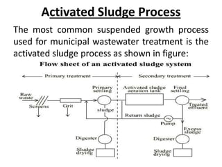
  • 1. Activated Sludge Process The most common suspended growth process used for municipal wastewater treatment is the activated sludge process as shown in figure:
  • 2. Activated Sludge Process Variables • The main variables of activated sludge process are the mixing regime, loading rate, and the flow scheme. • Mixing Regime • Generally two types of mixing regimes are of major interest in activated sludge process: plug flow and complete mixing. In the first one, the regime is characterized by orderly flow of mixed liquor through the aeration tank with no element of mixed liquor overtaking or mixing with any other element. There may be lateral mixing of mixed liquor but there must be no mixing along the path of flow.
  • 3. • In complete mixing, the contents of aeration tank are well stirred and uniform throughout. Thus, at steady state, the effluent from the aeration tank has the same composition as the aeration tank contents. • The type of mixing regime is very important as it affects (1) oxygen transfer requirements in the aeration tank, (2) susceptibility of biomass to shock loads, (3) local environmental conditions in the aeration tank, and (4) the kinetics governing the treatment process
  • 4. • Loading Rate • A loading parameter that has been developed over the years is the hydraulic retention time (HRT), Ɵ, d • Ɵ = V Q • V= volume of aeration tank, m3, and Q= sewage inflow, m3/d
  • 5. • Another empirical loading parameter is volumetric organic loading which is defined as the BOD applied per unit volume of aeration tank, per day. • A rational loading parameter which has found wider acceptance and is preferred is specific substrate utilization rate, q, per day. q= Q (SO - Se) V X
  • 6. • A similar loading parameter is mean cell residence time or sludge retention time (SRT), Ɵc, d • Ɵc = V X QwXr + (Q-QwXe) • where SO and Se are influent and effluent organic matter concentration respectively, measured as BOD5 (g/m3), X, Xe and Xr are MLSS concentration in aeration tank, effluent and return sludge respectively, and Qw= waste activated sludge rate.
  • 7. • Under steady state operation the mass of waste activated sludge is given by • QwXr = YQ (SO - Se) - kd XV • where Y= maximum yield coefficient (microbial mass synthesized / mass of substrate utilized) and kd = endogenous decay rate (d-1) . • From the above equation it is seen that • 1/Ɵc = Yq - kd • If the value of Se is small as compared SO, q may also be expressed as Food to Microorganism ratio, F/M • F/M = Q(SO- Se) / XV = QSO / XV
  • 8. • The Ɵc value adopted for design controls the effluent quality, and settleability and drainability of biomass, oxygen requirement and quantity of waste activated sludge.
  • 9. Main Types of Activated Sludge Process • The various types of activated sludge processes are listed below: 1. Conventional Activated Sludge Process 2. Tapered Aeration Process 3. Step Aeration Process 4. Contact Stabilization Process 5. Complete Mix Process 6. Modified Aeration Process 7. Extended Aeration Process.
  • 10. 1. Conventional Activated Sludge Process: • Fig. below shows a schematic diagram of the conventional activated sludge process which consists of an aeration tank, a secondary settling tank, a sludge return line and excess sludge waste line. The conventional activated sludge process is always preceded by primary settling. Thus in this case the mixture of the settled sewage from the primary settling tank and the returned activated sludge from the secondary settling tank is let in at the head end of the aeration tank and is aerated for a period of about 6 hours.
  • 11.
  • 12. • The conventional activated sludge process employs plug flow regime which is achieved by using the aeration tank of long and narrow configuration with length equal to 5 or more times the width. Because of plug flow regime, the demand of oxygen by the micro-organisms and the F/M ratio are the highest at the head end of the aeration tank and then gradually decreases. • However, air is supplied in the process at a uniform rate along the length of the aeration tank which leads to either oxygen deficiency in the initial zone or wasteful application of air in the subsequent reaches.
  • 13. • The other limitations of the conventional activated sludge process are: • (i) There is a lack of operational stability at times of excessive variations in rate and strength of influent sewage; • (ii) Biological upsets are common; and • (iii) Skilled operation is required. • In spite of these limitations, for historical reasons, the conventional activated sludge process is the most widely used type of the activated sludge process, and plants upto 300 Mid capacity have been built in India. The various shortcomings of the conventional activated sludge process are eliminated in the other activated sludge processes described below.
  • 14. 2. Tapered Aeration Process: • The objective of tapered aeration is to match the quantity of air supplied to the demand exerted by the micro-organisms, as the mixed liquor traverses the aeration tank. At the inlet of the aeration tank where fresh settled sewage and returned activated sludge first come in contact, the oxygen demand is very high. • The diffusers are spaced close together to achieve a high oxygenation rate and thus satisfy the demand. As the mixed liquor traverses the aeration tank, synthesis of new cells occurs, increasing the number of micro- organisms and decreasing the concentration of available food. This results in a lower food to micro- organism (F/M) ratio and a lowering of the oxygen demand.
  • 15. • The spacing of diffusers is thus increased towards the tank outlet to reduce the oxygenation rate. Thus tapered aeration process involves only a modification in the arrangement of diffusers in the aeration tank and the amount of air consumed as indicated above, and in a strict sense, it is only a modification of the conventional activated sludge process.
  • 16. • The tapered aeration process is widely used because of the following advantages: • (i) There is optimal application of air. • (ii) Due to reduced oxygenation less air is required which results in reducing the size of the compressors as well as the initial and operating costs. • (iii) Avoidance of over-aeration will inhibit the growth of nitrifying organisms, which may cause high oxygen demands.
  • 17. 3. Step Aeration Process: • The step aeration process is a modification of the conventional activated sludge process in which the settled sewage from the primary settling tank is introduced in the aeration tank at several points along the length of the aeration tank, while the returned activated sludge is introduced at the head end of the aeration tank as shown in Fig. below:
  • 18.
  • 19. • The aeration tank is subdivided into four or more parallel channels through the use of baffles. Each channel is a separate step, and the several steps are linked together in series. A typical flow sheet for this process is shown in Fig. 13.17. The returned activated sludge enters the first step of the aeration tank along with a portion of the settled sewage.
  • 20. • The influent sewage and returned activated sludge are mixed by the action of diffused or mechanical aeration, which is constant as the mixed liquor moves down the aeration tank. During this period, adsorption, flocculation, and oxidation of the organic matter take place. The mixed liquor is withdrawn at the tail end of the aeration tank and is settled in the secondary settling tank (or activated sludge settling tank), and from this tank activated sludge is returned at the rate of approximately 25 to 50 percent of the influent sewage flow rate.
  • 21. ASTP MLSS: What is MLSS (Mixed Liquor Suspended Solids) in wastewater treatment? Mixed Liquor Suspended Solids, or MLSS, is a measure of the total concentration of solids in an aeration tank, used in the wastewater treatment process. It is made up of bacteria, organic substances, and suspended non- biodegradable materials. Moreover, MLSS is thought to be a mixture of suspended particles and influent wastewater, which acts as a barometer for the system's biomass.
  • 22. Optimization of MLSS: Good MLSS in wastewater treatment Around 1500 mg/L to 5000 mg/L of MLSS is employed in traditional activated sludge wastewater treatment facilities. General range for effective working of aeration tank is 2500 to 3000 mg/L. For smaller aeration tanks where the treatment level is constant, higher MLSS concentration is advantageous. Higher MLSS is indicated by increased BOD loading, thickening sludge, high flow rates, insufficient settling times, and nutritional deficiency in the biomass.
  • 23. Nevertheless, aeration efficiency may decrease as MLSS concentration rises. Low MLSS therefore denotes that the DO concentration is not being maintained, fewer organisms are surviving, the flow rate is falling due to the absence of microorganisms, and both stalked and free-swimming ciliates are declining.
  • 24. Trickling Filters • Trickling filter is an attached growth process i.e. process in which microorganisms responsible for treatment are attached to an inert packing material. Packing material used in attached growth processes include rock, gravel, slag, sand, redwood, and a wide range of plastic and other synthetic materials.
  • 25.
  • 26. • Process Description • The wastewater in trickling filter is distributed over the top area of a vessel containing non- submerged packing material. • Air circulation in the void space, by either natural draft or blowers, provides oxygen for the microorganisms growing as an attached biofilm. • During operation, the organic material present in the wastewater is metabolised by the biomass attached to the medium. The biological slime grows in thickness as the organic matter abstracted from the flowing wastewater is synthesized into new cellular material.
  • 27. • The thickness of the aerobic layer is limited by the depth of penetration of oxygen into the microbial layer. • The micro-organisms near the medium face enter the endogenous phase as the substrate is metabolised before it can reach the micro-organisms near the medium face as a result of increased thickness of the slime layer and loose their ability to cling to the media surface. The liquid then washes the slime off the medium and a new slime layer starts to grow. This phenomenon of losing the slime layer is called sloughing. • The sloughed off film and treated wastewater are collected by an underdrainage which also allows circulation of air through filter. The collected liquid is passed to a settling tank used for solid- liquid separation.
  • 28. • Types of trickling filter • Depending upon the hydraulic and organic loadings applied, filters are classified into two types: • Low rate (standard rate) filter. • High-rate filter. • The standard-rate filter is operated with a hydraulic loading range of 1 to 4 m3/day/m2 and an organic BOD loading of 0.08 to 0.32 kg BOD/ m3/ day.
  • 29. The filter media usually rock with a depth of 1.8 to 3 m, with application to the filter by a rotating distributor. Many standard-rate filters are equipped to provide some recirculation during low-flow periods. The filter growth is often heavy and, in addition to the bacteria and protozoa, many types of worms, snails, and insect larvae can be found. The growth usually sloughs off at intervals, noticeably in spring and fall. The effluent from a standard-rate filter treating municipal wastewater is usually quite stable with BODs as low as 20 to 25 mg/l.
  • 30. Low-rate filter systems have fewer problems than other filters with filter flies, odors, and medium plugging because of the lower loading rate. 2. High-Rate Filters: High-rate filters usually have rock or synthetic media with a depth of 0.9 to 2.5 m. Recommended loadings range from 10 to 40 m3/m2.d and 0.32 to 1 kg BOD/m3 .d for organic loading. These filters are designed to receive wastewater continually, and practically all high-rate installations use recirculation.
  • 31. • Due to the heavy flow of wastewater over the media, more uniform sloughing of the filter growth occurs from high-rate filters. This sloughed material is somewhat lighter than from a standard-rate unit and therefore more difficult to settle.
  • 32. • Types of Filters • Trickling filters are classified as high rate or low rate, based on the organic and hydraulic loading applied to the unit. Sl.N o Design feature Low Rate TF HRTF 1. Hydraulic loading m3/m2.d 1 - 4 10 - 40 2. Organic loading, kg BOD/m3.d 0.08 – 0.32 0.32 – 1.0 3. Depth, m 1.8 - 3 0.9 – 2.5 4. Recirculation ratio 0 0.5 – 3 (domestic wastewater) - up to 8 for strong industrial wastewater.
  • 33. • The hydraulic loading rate is the total flow including recirculation applied on unit area of the filter in a day, while the organic loading rate is the 5 day 20°C BOD, excluding the BOD of the recirculant, applied per unit volume in a day. • Recirculation is generally not adopted in low rate filters. • A well operated low rate trickling filter in combination with secondary settling tank may remove 75 to 90% BOD and produce highly nitrified effluent. It is suitable for treatment of low to medium strength domestic wastewaters.
  • 34. • The high rate trickling filter, single stage or two stages are recommended for medium to relatively high strength domestic and industrial wastewater. The BOD removal efficiency is around 75 to90% but the effluent is only partially nitrified. • Single stage unit consists of a primary settling tank, filter, secondary settling tank and facilities for recirculation of the effluent. Two stage filters consist of two filters in series with a primary settling tank, an intermediate settling tank which may be omitted in certain cases and a final settling tank
  • 35. • Design of trickling filter. • In the design of an appropriate trickling filter system for a site, you must consider several components: some of the key components include: • Area and volume of the filter surface. • The depth of the filter media bed • The type of media. • The size of the pump. • Requirements for operating the trickling filter.
  • 36. • NRC equations The design of trickling filters is based upon empirical or semi-empirical equations. These equations are applicable to both low rate and high rate filters. It may be applied to single- or two- stage systems and is: …….. (1) C i = influent BOD C e = effluent BOD from the 1st stage Q = WW flow in m3/ min. V = filter volume in m3 F = recirculation factor
  • 37. for single-stage filter or the first stage of the two- stage system.