63027 03
- 1. between clay and nonclay minerals is that the nonclays
are composed primarily of bulky particles; whereas,
the particles of most of the clay minerals are platy, and
in a few cases they are needle shaped or tubular.
The great range in soil particle sizes in relation to
other particulate materials, electromagnetic wave
lengths, and other size-dependent factors can be seen
in Fig. 3.2. The liquid phase of most soil systems is
composed of water containing various types and
amounts of dissolved electrolytes. Organic compounds,
both soluble and immiscible, are found in soils at sites
Copyrighted Material
35
CHAPTER 3
Soil Mineralogy
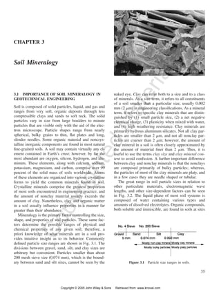
Figure 3.1 Particle size ranges in soils.
3.1 IMPORTANCE OF SOIL MINERALOGY IN
GEOTECHNICAL ENGINEERING
Soil is composed of solid particles, liquid, and gas and
ranges from very soft, organic deposits through less
compressible clays and sands to soft rock. The solid
particles vary in size from large boulders to minute
particles that are visible only with the aid of the elec-tron
microscope. Particle shapes range from nearly
spherical, bulky grains to thin, flat plates and long,
slender needles. Some organic material and noncrys-talline
inorganic components are found in most natural
fine-grained soils. A soil may contain virtually any el-ement
contained in Earth’s crust; however, by far the
most abundant are oxygen, silicon, hydrogen, and alu-minum.
These elements, along with calcium, sodium,
potassium, magnesium, and carbon, comprise over 99
percent of the solid mass of soils worldwide. Atoms
of these elements are organized into various crystalline
forms to yield the common minerals found in soil.
Crystalline minerals comprise the greatest proportion
of most soils encountered in engineering practice, and
the amount of nonclay material usually exceeds the
amount of clay. Nonetheless, clay and organic matter
in a soil usually influence properties in a manner far
greater than their abundance.
Mineralogy is the primary factor controlling the size,
shape, and properties of soil particles. These same fac-tors
determine the possible ranges of physical and
chemical properties of any given soil; therefore, a
priori knowledge of what minerals are in a soil pro-vides
intuitive insight as to its behavior. Commonly
defined particle size ranges are shown in Fig. 3.1. The
divisions between gravel, sand, silt, and clay sizes are
arbitrary but convenient. Particles smaller than about
200 mesh sieve size (0.074 mm), which is the bound-ary
between sand and silt sizes, cannot be seen by the
naked eye. Clay can refer both to a size and to a class
of minerals. As a size term, it refers to all constituents
of a soil smaller than a particular size, usually 0.002
mm (2 m) in engineering classifications. As a mineral
term, it refers to specific clay minerals that are distin-guished
by (1) small particle size, (2) a net negative
electrical charge, (3) plasticity when mixed with water,
and (4) high weathering resistance. Clay minerals are
primarily hydrous aluminum silicates. Not all clay par-ticles
are smaller than 2 m, and not all nonclay par-ticles
are coarser than 2 m; however, the amount of
clay mineral in a soil is often closely approximated by
the amount of material finer than 2 m. Thus, it is
useful to use the terms clay size and clay mineral con-tent
to avoid confusion. A further important difference
Copyright © 2005 John Wiley Sons Retrieved from: www.knovel.com
- 3. 37
Copyrighted Material
Figure 3.2 Characteristics of particles and particle dispersoids (adapted from Stanford Re-search
Institute Journal, Third Quarter, 1961).
Copyright © 2005 John Wiley Sons Retrieved from: www.knovel.com
- 4. 38 3 SOIL MINERALOGY
that have been affected by chemical spills, leaking
wastes, and contaminated groundwater. The gas phase,
in partially saturated soils, is usually air, although or-ganic
gases may be present in zones of high biological
activity or in chemically contaminated soils.
The mechanical properties of soils depend directly
on interactions of these phases with each other and
with applied potentials (e.g., stress, hydraulic head,
electrical potential, and temperature). Because of these
interactions, we cannot understand soil behavior in
terms of the solid particles alone. Nonetheless, the
structure of these particles tells us a great deal about
their surface characteristics and their potential inter-actions
3.3 INTERATOMIC BONDING
Primary Bonds
Only the outer shell or valence electrons participate in
the formation of primary interatomic bonds. There are
Copyrighted Material
Figure 3.3 Simplified representation of an atom.
with adjacent phases.
Interatomic and intermolecular bonding forces hold
matter together. Unbalanced forces exist at phase
boundaries. The nature and magnitude of these forces
influence the formation of soil minerals, the structure,
size, and shape of soil particles, and the physicochem-ical
phenomena that determine engineering properties
and behavior. In this chapter some aspects of atomic
and intermolecular forces, crystal structure, structure
stability, and characteristics of surfaces that are perti-nent
to the understanding of soil behavior are sum-marized
simply and briefly. This is followed by a
somewhat more detailed treatment of soil minerals and
their characteristics.
3.2 ATOMIC STRUCTURE
Current concepts of atomic structure and interparticle
bonding forces are based on quantum mechanics. An
electron can have only certain values of energy. Elec-tronic
energy can jump to a higher level by the ab-sorption
of radiant energy or drop to a lower level by
the emission of radiant energy. No more than two elec-trons
in an atom can have the same energy level, and
the spins of these two electrons must be in opposite
directions. Different bonding characteristics for differ-ent
elements exist because of the combined effects of
electronic energy quantization and the limitation on the
number of electrons at each energy level.
An atom may be represented in simplified form by
a small nucleus surrounded by diffuse concentric
‘‘clouds’’ of electrons (Fig. 3.3). The maximum num-ber
of electrons that may be located in each diffuse
shell is determined by quantum theory. The number
and arrangement of electrons in the outermost shell are
of prime importance for the development of different
types of interatomic bonding and crystal structure.
Interatomic bonds form when electrons in adjacent
atoms interact in such a way that their energy levels
are lowered. If the energy reduction is large, then a
strong, primary bond develops. The way in which the
bonding electrons are localized in space determines
whether or not the bonds are directional. The strength
and directionality of interatomic bonds, together with
the relative sizes of the bonded atoms, determine the
type of crystal structure assumed by a given compo-sition.
Copyright © 2005 John Wiley Sons Retrieved from: www.knovel.com
- 5. SECONDARY BONDS 39
three limiting types: covalent, ionic, and metallic. They
differ because of how the bonding electrons are local-ized
in space. The energy of these bonds per mole of
bonded atoms is from 60 103 to more than 400
103 joules (J; 15 to 100 kcal). As there are 6.023
1023 molecules per mole, it might be argued that such
bonds are weak; however, relative to the weight of an
atom they are very large.
Covalent Bonds In the covalent bond, one or more
bonding electrons are shared by two atomic nuclei to
complete the outer shell for each atom. Covalent bonds
are common in gases. If outer shell electrons are rep-resented
Copyrighted Material
by dots, then examples for (1) hydrogen gas,
(2) methane, and (3) chlorine gas are:
1. H H H:H
H
2.
C 4H H:C:H H
3.
:Cl Cl: :Cl:Cl:
In the solid state, covalent bonds form primarily be-tween
nonmetallic atoms such as oxygen, chlorine,
nitrogen, and fluorine. Since only certain electrons
participate in the bonding, covalent bonds are direc-tional.
As a result, atoms bonded covalently pack in
such a way that there are fixed bond angles.
Ionic Bonds Ionic bonds form between positively
and negatively charged free ions that acquire their
charge through gain or loss of electrons. Cations (pos-itively
charged atoms that are attracted by the cathode
in an electric field) form by atoms giving up one or
more loosely held electrons that lie outside a com-pleted
electron shell and have a high energy level. Met-als,
alkalies (e.g., sodium, potassium), and alkaline
earths (e.g., calcium, magnesium) form cations. Anions
(negatively charged atoms that are attracted to the an-ode)
are those atoms requiring only a few electrons to
complete their outer shell. Because the outer shells of
ions are complete, structures cannot form by electron
sharing as in the case of the covalent bond. Since ions
are electrically charged, however, strong electrical at-tractions
(and repulsions) can develop between them.
The ionic bond is nondirectional. Each cation at-tracts
all neighboring anions. In sodium chloride,
which is one of the best examples of ionic bonding, a
sodium cation attracts as many chlorine anions as will
fit around it. Geometric considerations and electrical
neutrality determine the actual arrangement of ioni-cally
bonded atoms.
As ionic bonding causes a separation between the
centers of positive and negative charge in a molecule,
the molecule will orient in an electrical field forming
a dipole. The strength of this dipole is expressed in
terms of the dipole moment . If two electrical charges
of magnitude e, where e is the electronic charge,
are separated by a distance d, then
d e (3.1)
Covalently bonded atoms may also produce dipolar
molecules.
Metallic Bonds Metals contain loosely held val-ence
electrons that hold the positive metal ions to-gether
but are free to travel through the solid material.
Metallic bonds are nondirectional and can exist only
among a large group of atoms. It is the large group of
electrons and their freedom to move that make metals
such good conductors of electricity and heat. The me-tallic
bond is of little importance in most soils.
Bonding in Soil Minerals
A combination of ionic and covalent bonding is typical
in most nonmetallic solids. Purely ionic or covalent
bonding is a limiting condition that is the exception
rather than the rule in most cases. Silicate minerals are
the most abundant constituents of most soils. The in-teratomic
bond in silica (SiO2) is about half covalent
and half ionic.
3.4 SECONDARY BONDS
Secondary bonds that are weak relative to ionic and
covalent bonds also form between units of matter. They
may be strong enough to determine the final arrange-ments
of atoms in solids, and they may be sources of
attraction between very small particles and between
liquids and solid particles.
The Hydrogen Bond
If a hydrogen ion forms the positive end of a dipole,
then its attraction to the negative end of an adjacent
molecule is termed a hydrogen bond. Hydrogen bonds
form only between strongly electronegative atoms such
as oxygen and fluorine because these atoms produce
the strongest dipoles. When the electron is detached
from a hydrogen atom, such as when it combines with
oxygen to form water, only a proton remains. As the
electrons shared between the oxygen and hydrogen at-oms
spend most of their time between the atoms, the
oxygens act as the negative ends of dipoles, and the
hydrogen protons act as the positive ends. The positive
and negative ends of adjacent water molecules tie them
together forming water and ice.
The strength of the hydrogen bond is much greater
than that of other secondary bonds because of the small
size of the hydrogen ion. Hydrogen bonds are impor-
Copyright © 2005 John Wiley Sons Retrieved from: www.knovel.com
- 6. 40 3 SOIL MINERALOGY
within the lattice where atoms or atomic groups
Copyrighted Material
Figure 3.4 Examples of some common crystals. (hkl) are
cleavage plane indices. From Dana’s Manual of Mineralogy,
by C. S. Hurlbut, 16th Edition. Copyright 1957 by John
Wiley Sons. Reprinted with permission from John Wiley
Sons.
tant in determining some of the characteristics of the
clay minerals and in the interaction between soil par-ticle
surfaces and water.
van der Waals Bonds
Permanent dipole bonds such as the hydrogen bond are
directional. Fluctuating dipole bonds, commonly
termed van der Waals bonds, also exist because at any
one time there may be more electrons on one side of
the atomic nucleus than on the other. This creates weak
instantaneous dipoles whose oppositely charged ends
attract each other.
Although individual van der Waals bonds are weak,
typically an order of magnitude weaker than a hydro-gen
bond, they are nondirectional and additive between
atoms. Consequently, they decrease less rapidly with
distance than primary valence and hydrogen bonds
when there are large groups of atoms. They are strong
enough to determine the final arrangements of groups
of atoms in some solids (e.g., many polymers), and
they may be responsible for small cohesions in fine-grained
soils. Van der Waals forces are described fur-ther
in Chapter 7.
3.5 CRYSTALS AND THEIR PROPERTIES
Particles composed of mineral crystals form the
greatest proportion of the solid phase of a soil. A crys-tal
is a homogeneous body bounded by smooth plane
surfaces that are the external expression of an orderly
internal atomic arrangement. A solid without internal
atomic order is termed amorphous.
Crystal Formation
Crystals may form in three ways:
1. From Solution Ions combine as they separate
from solution and gradually build up a solid of
definite structure and shape. Halite (sodium chlo-ride)
and other evaporites are examples.
2. By Fusion Crystals form directly from a liquid
as a result of cooling. Examples are igneous rock
minerals solidified from molten rock magma and
ice from water.
3. From Vapor Although not of particular impor-tance
in the formation of soil minerals, crystals
can form directly from cooling vapors. Examples
include snowflakes and flowers of sulfur.
Examples of some common crystals are shown in
Fig. 3.4.
Characteristics of Crystals
Certain crystal characteristics are used to distinguish
different classes or groups of minerals. Variations in
these characteristics result in different properties.
1. Structure The atoms in a crystal are arranged
in a definite orderly manner to form a three-dimensional
network termed a lattice. Positions
Copyright © 2005 John Wiley Sons Retrieved from: www.knovel.com
- 7. CRYSTALS AND THEIR PROPERTIES 41
are located are termed lattice points. Only 14 dif-ferent
arrangements of lattice points in space are
possible. These are the Bravais space lattices,
and they are illustrated in Fig. 3.5.
The smallest subdivision of a crystal that still
possesses the characteristic composition and spa-tial
same substance are constant. Crystals break
along smooth cleavage planes. Cleavage planes
lie between planes in which the atoms are most
Copyrighted Material
arrangement of atoms in the crystal is the unit
cell. The unit cell is the basic repeating unit of
the space lattice.
2. Cleavage and Outward Form The angles be-tween
corresponding faces on crystals of the
Figure 3.5 Unit cells of the 14 Bravais space lattices. The capital letters refer to the type
of cell: P, primitive cell; C, cell with a lattice point in the center of two parallel faces; F,
cell with a lattice point in the center of each face; I, cell with a lattice point in the center
of the interior; R, rhombohedral primitive cell. All points indicated are lattice points. There
is no general agreement on the unit cell to use for the hexagonal Bravais lattice; some prefer
the P cell shown with solid lines, and others prefer the C cell shown in dashed lines (modified
from Moffatt et al., 1965).
Copyright © 2005 John Wiley Sons Retrieved from: www.knovel.com
- 8. 42 3 SOIL MINERALOGY
Copyrighted Material
Figure 3.6 The six crystal systems.
densely packed. This is because the center-to-center
distance between atoms on opposite sides
of the plane is greater than along other planes
through the crystal. As a result, the strength along
cleavage planes is less than in other directions.
3. Optical Properties The specific atomic arrange-ments
within crystals allow light diffraction and
polarization. These properties are useful for iden-tification
and classification. Identification of rock
minerals by optical means is common. Optical
studies in soil are less useful because of the small
sizes of most soil particles.
4. X-ray and Electron Diffraction The orderly
atomic arrangements in crystals cause them to
behave with respect to X-ray and electron beams
in much the same way as does a diffraction grat-ing
with respect to visible light. Different crystals
yield different diffraction patterns. This makes X-ray
diffraction a powerful tool for the study and
identification of very small particles, such as clay
that cannot be seen using optical means.
5. Symmetry There are 32 distinct crystal classes
based on symmetry considerations involving the
arrangement and orientation of crystal faces.
These 32 classes may be grouped into 6 crystal
systems with the classes within each system bear-ing
close relationships to each other.
The six crystal systems are illustrated in Fig. 3.6.
Crystallographic axes parallel to the intersection edges
of prominent crystal faces are established for each of
the six crystal systems. In most crystals, these axes will
also be symmetry axes or axes normal to symmetry
planes. In five of the six systems, the crystals are re-ferred
to three crystallographic axes. In the sixth (the
hexagonal system), four axes are used. The axes are
denoted by a, b, c (a1, a2, a3, and c in the hexagonal
system) and the angles between the axes by , ,
and .
Isometric or Cubic System There are three mutu-ally
perpendicular axes of equal length. Mineral
examples are galena, halite, magnetite, and pyrite.
Hexagonal System Three equal horizontal axes ly-ing
in the same plane intersect at 60 with a fourth
axis perpendicular to the other three and of dif-ferent
length. Examples are quartz, brucite, cal-cite,
and beryl.
Tetragonal System There are three mutually per-pendicular
axes, with two horizontal of equal
length, but different than that of the vertical axis.
Zircon is an example.
Orthorhombic System There are three mutually
perpendicular axes, each of different length. Ex-amples
include sulfur, anhydrite, barite, diaspore,
and topaz.
Monoclinic System There are three unequal axes,
two inclined to each other at an oblique angle,
with the third perpendicular to the other two. Ex-amples
are orthoclase feldspar, gypsum, musco-vite,
biotite, gibbsite, and chlorite.
Triclinic System Three unequal axes intersect at
oblique angles. Examples are plagioclase feldspar,
kaolinite, albite, microcline, and turquoise.
3.6 CRYSTAL NOTATION
Miller indices are used to describe plane orientations
and directions in a crystal. This information, along
with the distances that separate parallel planes is im-portant
for the identification and classification of dif-ferent
minerals. All lengths are expressed in terms of
unit cell lengths. Any plane through a crystal may be
described by intercepts, in terms of unit cell lengths,
on the three or four crystallographic axes for the sys-tem
in which the crystal falls. The reciprocals of these
intercepts are used to index the plane. Reciprocals are
used to avoid fractions and to account for planes par-allel
to an axis (an intercept of infinity equals an index
value of 0).
Copyright © 2005 John Wiley Sons Retrieved from: www.knovel.com
- 9. CRYSTAL NOTATION 43
lengths. Take plane mnp in Fig. 3.7a as an example.
The intercepts of this plane are a 1, b 1, and
c 1. The Miller indices of this plane are found by
taking the reciprocals of these intercepts and clearing
of fractions. Thus,
Reciprocals are 1/1, 1/1, 1/1
Miller indices are (111)
The indices are always enclosed within parentheses
and indicated in the order abc without commas. Paren-
Copyrighted Material
An example illustrates the determination and mean-ing
of Miller indices. Consider the mineral muscovite,
a member of the monoclinic system. It has unit cell
dimensions of a 0.52 nanometers (nm), b 0.90
nm, c 2.0 nm, and 95 30. Both the compo-sition
and crystal structure of muscovite are similar to
those of some of the important clay minerals.
The muscovite unit cell dimensions and intercepts
are shown in Fig. 3.7a. The intercepts for any plane of
interest are first determined in terms of unit cell
Figure 3.7 Miller indices: (a) Unit cell of muscovite, (b) (002) plane for muscovite, (c)
(014) plane for muscovite, and (d) (623) plane for muscovite.
Copyright © 2005 John Wiley Sons Retrieved from: www.knovel.com
- 10. 44 3 SOIL MINERALOGY
Table 3.1 Atomic Packing, Structure, and Structural
Stability
Radius
Ratioa Nb Geometry Example Stability
0–0.155 2 Line — —
0.155–
0.225
3 Triangle (CO3)2 Very high
Material
0.225–
0.414
Copyrighted 4 Tetrahedron (SiO4)4 Moderately
high
0.414–
0.732
6 Octahedron [Al(OH)6]3 High
0.732–
1.0
8 Body-cen-tered
cube
Iron Low
1.0 12 Sheet K–O bond
in mica
Very low
aRange of cation to anion diameter ratios over which
stable coordination is expected.
bCoordination number.
Table 3.2 Relative Stabilities of Some Soil Mineral
Structural Units
Structural Unit
Approximate
Relative Bond
Strength
(Valence/N)
Silicon tetrahedron, (SiO4)4 4/4 1
Aluminum tetrahedron, [Al(OH)4]1 3/4
Aluminum octahedron, [Al(OH)6]3 3/6 1/2
Magnesium octahedron, [Mg(OH)6]4 2/6 1/3
K–O12
23 1/12
theses are always used to indicate crystallographic
planes, whereas brackets are used to indicate direc-tions.
For example, [111] designates line oq in Fig.
3.7a. Additional examples of Miller indices for planes
through the muscovite crystal are shown in Figs. 3.7b,
3.7c, and 3.7d. A plane that cuts a negative axis is
designated by placing a bar over the index that pertains
to the negative intercept (Fig. 3.7d). The general index
(hkl) is used to refer to any plane that cuts all three
axes. Similarly (h00) designates a plane cutting only
the a axis, (h0l) designates a plane parallel to the b
axis, and so on. For crystals in the hexagonal system,
the Miller index contains four numbers. The (001)
planes of soil minerals are of particular interest be-cause
they are indicative of specific clay mineral types.
3.7 FACTORS CONTROLLING CRYSTAL
STRUCTURES
Organized crystal structures do not develop by chance.
The most stable arrangement of atoms in a crystal is
that which minimizes the energy per unit volume. This
is achieved by preserving electrical neutrality, satisfy-ing
bond directionality, minimizing strong ion repul-sions,
and packing atoms closely together.
If the interatomic bonding is nondirectional, then the
relative atomic sizes have a controlling influence on
packing. The closest possible packing will maximize
the number of bonds per unit volume and minimize the
bonding energy. If interatomic bonds are directional,
as is the case for covalent bonds, then both bond angles
and atomic size are important.
Anions are usually larger than cations because of
electron transfer from cations to anions. The number
of nearest neighbor anions that a cation possesses in a
structure is termed the coordination number (N) or li-gancy.
Possible values of coordination number in solid
structures are 1 (trivial), 2, 3, 4, 6, 8, and 12. The
relationships between atomic sizes, expressed as the
ratio of cationic to anionic radii, coordination number,
and the geometry formed by the anions are indicated
in Table 3.1.
Most solids do not have bonds that are completely
nondirectional, and the second nearest neighbors may
influence packing as well as the nearest neighbors.
Even so, the predicted and observed coordination num-bers
are in quite good agreement for many materials.
The valence of the cation divided by the number of
coordinated anions is an approximate indication of the
relative bond strength, which, in turn, is related to the
structural stability of the unit. Some of the structural
units common in soil minerals and their relative bond
strengths are listed in Table 3.2.
The basic coordination polyhedra are seldom elec-trically
neutral. In crystals formed by ionic bonded pol-yhedra,
the packing maintains electrical neutrality and
minimizes strong repulsions between ions with like
charge. In such cases, the valence of the central cation
equals the total charge of the coordinated anions, and
the unit is really a molecule. Units of this type are held
together by weaker, secondary bonds. An example is
brucite, a mineral that has the composition Mg(OH)2.
The Mg2 ions are in octahedral coordination with six
(OH) ions forming a sheet structure in such a way
that each (OH) is shared by 3Mg2. In a sheet con-taining
N Mg2 ions, therefore, there must be 6N/3
2N (OH) ions. Thus, electrical neutrality results, and
the sheet is in reality a large molecule. Successive oc-
Copyright © 2005 John Wiley Sons Retrieved from: www.knovel.com
- 11. SURFACES 45
tahedral sheets are loosely bonded by van der Waals
forces. Because of this, brucite has perfect basal cleav-age
parallel to the sheets.
Cations concentrate their charge in a smaller volume
than do anions, so the repulsion between cations is
greater than between anions. Cationic repulsions are
minimized when the anions are located at the centers
of coordination polyhedra. If the cations have a low
valence, then the anion polyhedra pack as closely as
possible to minimize energy per unit volume. If, on the
other hand, the cations are small and highly charged,
then the units arrange in a variety of ways in response
to the repulsions. The silicon cation is in this category.
Copyrighted Material
3.8 SILICATE CRYSTALS
Small cations form structures with coordination num-bers
of 3 and 4 (Table 3.1). These cations are often
highly charged and generate strong repulsions between
adjacent triangles or tetrahedra. As a result, such struc-tures
share only corners and possibly edges, but never
faces, since to do so would bring the cations too close
together. The radius of silicon is only 0.039 nm,
whereas that of oxygen is 0.132 nm. Thus silicon and
oxygen combine in tetrahedral coordination, with the
silicon occupying the space at the center of the tetra-hedron
formed by the four oxygens. The tetrahedral
arrangement satisfies both the directionality of the
bonds (the Si–O bond is about half covalent and half
ionic) and the geometry imposed by the radius ratio.
Silicon is very abundant in Earth’s crust, amounting to
about 25 percent by weight, but only 0.8 percent by
volume. Almost half of igneous rock by weight and
91.8 percent by volume is oxygen.
Silica tetrahedra join only at their corners, and
sometimes not at all. Thus many crystal structures are
possible, and there is a large number of silicate min-erals.
Silicate minerals are classified according to how
the silica tetrahedra (SiO4)4 associate with each other,
as shown in Fig. 3.8. The tetrahedral combinations in-crease
in complexity from the beginning to the end of
the figure. The structural stability increases in the same
direction.
Island (independent) silicates are those in which the
tetrahedra are not joined to each other. Instead, the four
excess oxygen electrons are bonded to other positive
ions in the crystal structure. In the olivine group, the
minerals have the composition R2 2
SiO4. Garnets
4
contain cations of different valences and coordination
numbers R2 R3(SiO). The negative charge of the
3
2
43SiO4 group in zircon is all balanced by the single Zr4.
Ring and chain silicates are formed when corners of
tetrahedra are shared. The formulas for these structures
contain (SiO3)2. The pyroxene minerals are in this
class. Enstatite, MgSiO3, is a simple member of this
group. Some of the positions normally occupied by
Si4 in single-chain structures may be filled by Al3.
Substitution of ions of one kind by ions of another
type, having either the same or different valence, but
the same crystal structure, is termed isomorphous sub-stitution.
The term substitution implies a replacement
whereby a cation in the structure is replaced at some
time by a cation of another type. In reality, however,
the replaced cations were never there, and the mineral
was formed with its present proportions of the different
cations in the structure.
Double chains of indefinite length may form with
(Si4O11)6 as part of the structure. The amphiboles fall
into this group (Fig. 3.8). Hornblendes have the same
basic structure, but some of the Si4 positions are filled
by Al3. The cations Na and K can be incorporated
into the structure to satisfy electrical neutrality; Al3,
Fe3, Fe2, and Mn2 can replace part of the Mg2 in
sixfold coordination, and the (OH) group can be re-placed
by F.
In sheet silicates three of the four oxygens of each
tetrahedron are shared to give structures containing
(Si2O5)2. The micas, chlorites, and many of the clay
minerals contain silica in a sheet structure. Framework
silicates result when all four of the oxygens are shared
with other tetrahedra. The most common example is
quartz. In quartz, the silica tetrahedra are grouped to
form spirals. The feldspars also have three-dimensional
framework structures. Some of the silicon positions are
filled by aluminum, and the excess negative charge
thus created is balanced by cations of high coordina-tion
such as potassium, calcium, sodium, and barium.
Differences in the amounts of this isomorphous sub-stitution
are responsible for the different members of
the feldspar family.
3.9 SURFACES
All liquids and solids terminate at a surface, or phase
boundary, on the other side of which is matter of a
different composition or state. In solids, atoms are
bonded into a three-dimensional structure, and the ter-mination
of this structure at a surface, or phase bound-ary,
produces unsatisfied force fields. In a fine-grained
particulate material such as clay soil the surface area
may be very large relative to the mass of the material,
and, as is emphasized throughout this book, the influ-ences
of the surface forces on properties and behavior
may be very large.
Unsatisfied forces at solid surfaces may be balanced
in any of the following ways:
Copyright © 2005 John Wiley Sons Retrieved from: www.knovel.com
- 12. 46 3 SOIL MINERALOGY
Copyrighted Material
Figure 3.8 Silica tetrahedral arrangements in different silicate mineral structures. Reprinted
Gillott (1968) with permission from Elsevier Science Publishers BV.
Copyright © 2005 John Wiley Sons Retrieved from: www.knovel.com
- 13. SURFACES 47
Material
Copyrighted Figure 3.8 (Continued)
1. Attraction and adsorption of molecules from the
adjacent phase
2. Cohesion with the surface of another mass of the
same substance
3. Solid-state adjustments of the structure beneath
the surface.
Each unsatisfied bond force is significant relative to
the weight of atoms and molecules. The actual mag-nitude
of 1011 N or less, however, is infinitesimal
compared to the weight of a piece of gravel or a grain
of sand. On the other hand, consider the effect of re-ducing
particle size. A cube 10 mm on an edge has a
Copyright © 2005 John Wiley Sons Retrieved from: www.knovel.com
- 14. 48 3 SOIL MINERALOGY
surface area of 6.0 104 m2. If it is cut in half in
the three directions, eight cubes result, each 5 mm on
an edge. The surface area now is 12.0 104 m2. If
the cubes are further divided to 1 m on an edge, the
surface becomes 6.0 m2 for the same 1000 mm3 of
material. Thus, as a solid is subdivided into smaller
and smaller units, the proportion of surface area to
weight becomes larger and larger. For a given particle
shape, the ratio of surface area to volume is inversely
proportional to some effective particle diameter.
For many materials when particle size is reduced to
1 or 2 m or less the surface forces begin to exert a
distinct influence on the behavior. Study of the behav-ior
Copyrighted Material
of particles of this size and less requires consider-ations
of colloidal and surface chemistry. Most clay
particles behave as colloids, both because of their
small size and because they have unbalanced surface
electrical forces as a result of isomorphous substitu-tions
within their structure.
Montmorillonite, which is one of the members of
the smectite clay mineral group (see Section 3.17),
may break down into particles that are only 1 unit cell
thick (1.0 nm) when in a dispersed state and have a
specific surface area of 800 m2 /g. If all particles con-tained
in about 10 g of this clay could be spread out
side by side, they would cover a football field.
3.10 GRAVEL, SAND, AND SILT PARTICLES
The physical characteristics of cohesionless soils, that
is, gravel, sand, and nonplastic silts, are determined
primarily by particle size, shape, surface texture, and
size distribution. The mineral composition determines
hardness, cleavage, and resistance to physical and
chemical breakdown. Some carbonate and sulfate min-erals,
such as calcite and gypsum, are sufficiently sol-uble
that their decomposition may be significant within
the time frame of many projects. In many cases, how-ever,
the nonclay particles may be treated as relatively
inert, with interactions that are predominantly physical
in nature. Evidence of this is provided by the soils on
the Moon. Lunar soils have a silty, fine sand gradation;
however, their compositions are totally different than
those of terrestrial soils of the same gradation. The
engineering properties of the two materials are sur-prisingly
similar, however.
The gravel, sand, and most of the silt fraction in a
soil are composed of bulky, nonclay particles. As most
soils are the products of the breakdown of preexisting
rocks and soils, they are weathering products. Thus,
the predominant mineral constituents of any soil are
those that are one or more of the following:
1. Very abundant in the source material
2. Highly resistant to weathering, abrasion, and im-pact
3. Weathering products
The nonclays are predominantly rock fragments or
mineral grains of the common rock-forming minerals.
In igneous rocks, which are the original source mate-rial
for many soils, the most prevalent minerals are the
feldspars (about 60 percent) and the pyroxenes and
amphiboles (about 17 percent). Quartz accounts for
about 12 percent of these rocks, micas for 4 percent,
and other minerals for about 8 percent.
However, in most soils, quartz is by far the most
abundant mineral, with small amounts of feldspar and
mica also present. Pyroxenes and amphiboles are sel-dom
found in significant amounts. Carbonate minerals,
mainly calcite and dolomite, are also found in some
soils and can occur as bulky particles, shells, precipi-tates,
or in solution. Carbonates dominate the compo-sition
of some deep-sea sediments. Sulfates, in various
forms, are found primarily in soils of semiarid and arid
regions, with gypsum (CaSO4 2H2O) being the most
common. Iron and aluminum oxides are abundant in
residual soils of tropical regions.
Quartz is composed of silica tetrahedra grouped to
form spirals, with all tetrahedral oxygens bonded to
silicon. The tetrahedral structure has a high stability.
In addition, the spiral grouping of tetrahedra produces
a structure without cleavage planes, quartz is already
an oxide, there are no weakly bonded ions in the struc-ture,
and the mineral has high hardness. Collectively,
these factors account for the high persistence of quartz
in soils.
Feldspars are silicate minerals with a three-dimensional
framework structure in which part of the
silicon is replaced by aluminum. The excess negative
charge resulting from this replacement is balanced by
cations such as potassium, calcium, sodium, strontium,
and barium. As these cations are relatively large, their
coordination number is also large. This results in an
open structure with low bond strengths between units.
Consequently, there are cleavage planes, the hardness
is only moderate, and feldspars are relatively easily
broken down. This accounts for their lack of abun-dance
in soils compared to their abundance in igneous
rocks.
Mica has a sheet structure composed of tetrahedral
and octahedral units. Sheets are stacked one on the
other and held together primarily by potassium ions in
12-fold coordination that provide an electrostatic bond
of moderate strength. In comparison with the intralayer
bonds, however, this bond is weak, which accounts for
the perfect basal cleavage of mica. As a result of the
Copyright © 2005 John Wiley Sons Retrieved from: www.knovel.com
- 15. STRUCTURAL UNITS OF THE LAYER SILICATES 49
thin-plate morphology of mica flakes, sand and silts
containing only a few percent mica may exhibit high
compressibility when loaded and large swelling when
unloaded, as may be seen in Fig. 3.9. The amphiboles,
pyroxenes, and olivine have crystal structures that are
rapidly broken down by weathering; hence they are
absent from most soils.
Some examples of silt and sand particles from dif-ferent
Copyrighted Material
soils are shown in Fig. 3.10. Angularity and
roundness can be used to describe particle shapes, as
shown in Fig. 3.11. Elongated and platy particles can
develop preferred orientations, which can be respon-sible
for anisotropic properties within a soil mass. The
surface texture of the grains influences the stress–
deformation and strength properties.
3.11 SOIL MINERALS AND MATERIALS
FORMED BY BIOGENIC AND GEOCHEMICAL
PROCESSES
Evaporite deposits formed by precipitation of salts
from salt lakes and seas as a result of the evaporation
of water are sometimes found in layers that are several
meters thick. The major constituents of seawater and
their relative proportions are listed in Table 3.3. Also
listed are some of the more important evaporite de-posits.
Figure 3.9 Swelling index as a function of mica content for
coarse-grained mixtures (data from Terzaghi, 1931).
In some areas alternating layers of evaporite and
clay or other fine-grained sediments are formed during
cyclic wet and dry periods.
Many limestones, as well as coral, have been formed
by precipitation or from the remains of various organ-isms.
Because of the much greater solubility of lime-stone
than most other rock types, it may be the source
of special problems caused by solution channels and
cavities under foundations.
Chemical sediments and rocks in freshwater lakes,
ponds, swamps, and bays are occasionally encountered
in civil engineering projects. Biochemical processes
form marl, which ranges from relatively pure calcium
carbonate to mixtures with mud and organic matter.
Iron oxide is formed in some lakes. Diatomite or dia-tomaceous
earth is essentially pure silica formed from
the skeletal remains of small (up to a few tenths of a
millimeter) freshwater and saltwater organisms. Owing
to their solubility limestone, calcite, gypsum, and other
salts may cause special geotechnical problems.
Oxidation and reduction of pyrite-bearing earth ma-terials,
that is, soils and rocks containing FeS2, can be
the source of many types of geotechnical problems,
including ground heave, high swell pressures, forma-tion
of acid drainage, damage to concrete, and corro-sion
of steel (Bryant et al., 2003). The chemical and
biological processes and consequences of pyritic re-actions
are covered in Sections 8.3, 8.11, and 8.16.
More than 12 percent of Canada is covered by a
peaty material, termed muskeg, composed almost en-tirely
of decaying vegetation. Peat and muskeg may
have water contents of 1000 percent or more; they are
very compressible, and they have low strength. The
special properties of these materials and methods for
analysis of geotechnical problems associated with
them are given by MacFarlane (1969), Dhowian and
Edil (1980), and Edil and Mochtar (1984).
3.12 SUMMARY OF NONCLAY MINERAL
CHARACTERISTICS
Important compositional, structural, and morphological
characteristics of the important nonclay minerals found
in soils are summarized in Table 3.4. Of these miner-als,
quartz is by far the most common, both in terms
of the number of soils in which it is found and its
abundance in a typical soil. Feldspar and mica are fre-quently
present in small percentages.
3.13 STRUCTURAL UNITS OF THE LAYER
SILICATES
Clay minerals in soils belong to the mineral family
termed phyllosilicates, which also contains other layer
Copyright © 2005 John Wiley Sons Retrieved from: www.knovel.com
- 16. 50 3 SOIL MINERALOGY
Material
Copyrighted Figure 3.10 Photomicrographs of sand and silt particles from several soils: (a) Ottawa stan-dard
sand, (b) Monterey sand, (c) Sacramento River sand, (d) Eliot sand, and (e) lunar soil
mineral grains (photo courtesy Johnson Space Center). Squares in background area are 11
mm. (ƒ) Recrystallized breccia particles from lunar soil (photo courtesy of NASA Johnson
Space Center). Squares in background grid are 11 mm.
silicates such as serpentine, pyrophyllite, talc, mica,
and chlorite. Clay minerals occur in small particle
sizes, and their unit cells ordinarily have a residual
negative charge that is balanced by the adsorption of
cations from solution.
The structures of the common layer silicates are
made up of combinations of two simple structural
units, the silicon tetrahedron (Fig. 3.12) and the alu-minum
or magnesium octahedron (Fig. 3.13). Different
clay mineral groups are characterized by the stacking
arrangements of sheets1 (sometimes chains) of these
1 In conformity with the nomenclature of the Clay Minerals Society
(Bailey et al., 1971), the following terms are used: a plane of atoms,
a sheet of basic structural units, and a layer of unit cells composed
of two, three, or four sheets.
units and the manner in which two successive two- or
three-sheet layers are held together.
Differences among minerals within clay mineral
groups result primarily from differences in the type and
amount of isomorphous substitution within the crystal
structure. Possible substitutions are nearly endless in
number, and the crystal structure arrangement may
range from very poor to nearly perfect. Fortunately for
engineering purposes, knowledge of the structural and
compositional characteristics of each group, without
detailed study of the subtleties of each specific mineral,
is adequate.
Silica Sheet
In most clay mineral structures, the silica tetrahedra
are interconnected in a sheet structure. Three of the
Copyright © 2005 John Wiley Sons Retrieved from: www.knovel.com
- 17. STRUCTURAL UNITS OF THE LAYER SILICATES 51
Material
Copyrighted Figure 3.10 (Continued)
Figure 3.11 Sand and silt size particle shapes as seen in
silhouette.
four oxygens in each tetrahedron are shared to form a
hexagonal net, as shown in Figs. 3.12b and 3.14. The
bases of the tetrahedra are all in the same plane, and
the tips all point in the same direction. The structure
has the composition (Si4O10)4 and can repeat indefi-nitely.
Electrical neutrality can be obtained by replace-ment
of four oxygens by hydroxyls or by union with
a sheet of different composition that is positively
charged. The oxygen-to-oxygen distance is 2.55 ang-stroms
(A˚ ),2 the space available for the silicon ion is
0.55 A˚
, and the thickness of the sheet in clay mineral
structures is 4.63 A˚
(Grim, 1968).
2 In conformity with the SI system of units, lengths should be given
in nanometers. For convenience, however, the angstrom unit is re-tained
for atomic dimensions, where 1 A˚
0.1 nm.
Silica Chains
In some of the less common clay minerals, silica tet-rahedra
are arranged in bands made of double chains
of composition (Si4O11)6. Electrical neutrality is
achieved and the bands are bound together by alumi-num
and/or magnesium ions. A diagrammatic sketch
of this structure is shown in Fig. 3.8. Minerals in this
group resemble the amphiboles in structure.
Octahedral Sheet
This sheet structure is composed of magnesium or alu-minum
in octahedral coordination with oxygens or hy-droxyls.
In some cases, other cations are present in
place of Al3 and Mg2, such as Fe2, Fe3, Mn2,
Ti4, Ni2, Cr3, and Li. Figure 3.13b is a schematic
diagram of such a sheet structure. The oxygen-to-oxygen
distance is 2.60 A˚
, and the space available for
the octahedrally coordinated cation is 0.61 A˚
. The
thickness of the sheet is 5.05 A˚
in clays (Grim, 1968).
If the cation is trivalent, then normally only two-thirds
of the possible cationic spaces are filled, and the
structure is termed dioctahedral. In the case of alu-minum,
the composition is Al2(OH)6. This composition
and structure form the mineral gibbsite. When com-bined
with silica sheets, as is the case in clay mineral
Copyright © 2005 John Wiley Sons Retrieved from: www.knovel.com
- 18. 52 3 SOIL MINERALOGY
Table 3.3 Major Constituents of Seawater and Evaporite Deposits
Ion Grams per Liter
Percent by Weight
of Total Solids Important Evaporite Deposits
Sodium, Na 10.56 30.61 Anhydrite CaSO4
Magnesium, Mg2 1.27 3.69 Barite BaSO4
Calcium, Ca2 0.40 1.16 Celesite SrSO4
Potassium, K 0.38 1.10 Kieserite MgSO4 H2O
Strontium, Sr2 0.013 0.04 Gypsum CaSO4 2H2O
Chloride, Cl 18.98 55.04 Polyhalite Ca2K2Mg(SO4) 2H2O
Sulfate, SO4
Copyrighted Material
2 2.65 7.68 Bloedite Ma2Mg(SO4)2 4H2O
Bicarbonate, HCO3
0.14 0.41 Hexahydrite MgSO4 6H2O
Bromide, Br 0.065 0.19 Epsomite MgSO4 7H2O
Fluoride, F 0.001 — Kainite K4Mg4(Cl/SO4) 1 1H2
O
Boric Acid, H3BO3 0.026 0.08 Halite NaCl
34.485 100.00 Sylvite KCl
Flourite CaF2
Bischofite MgCl2 6H2O
Carnallite KMgCl3 6H2O
Adapted from data by Degens (1965).
structures, an aluminum octahedral sheet is referred to
as a gibbsite sheet.
If the octahedrally coordinated cation is divalent,
then normally all possible cation sites are occupied and
the structure is trioctahedral. In the case of magne-sium,
the composition is Mg3(OH)6, giving the mineral
brucite. In clay mineral structures, a sheet of magne-sium
octahedra is termed a brucite sheet.
Schematic representations of the sheets are useful
for simplified diagrams of the structures of the differ-ent
clay minerals:
Silica sheet or
Octahedral sheet (Various cations in octahedral coordination)
Gibbsite sheet (Octahedral sheet cations are mainly aluminum)
Brucite sheet (Octahedral sheet cations are mainly magnesium)
Water layers are found in some structures and may
be represented by for each molecular layer.
Atoms of a specific type, for example, potassium, are
represented thus: K .
The diagrams are indicative of the clay mineral layer
structure. They do not indicate the correct width-to-length
ratios for the actual particles. The structures
shown are idealized; in actual minerals, irregular sub-stitutions
and interlayering or mixed-layer structures
are common. Furthermore, direct assembly of the basic
units does not necessarily form the naturally occurring
minerals. The ‘‘building block’’ approach is useful,
however, for the development of conceptual models.
3.14 SYNTHESIS PATTERN AND
CLASSIFICATION OF THE CLAY MINERALS
The manner in which atoms are assembled into tetra-hedral
and octahedral units, followed by the formation
of sheets and their stacking to form layers that combine
to produce the different clay mineral groups is illus-trated
in Fig. 3.15. The basic structures shown in the
bottom row of Fig. 3.15 comprise the great prepon-derance
of the clay mineral types that are found in
soils.
Grouping the clay minerals according to crystal
structure and stacking sequence of the layers is con-venient
since members of the same group have gen-
Copyright © 2005 John Wiley Sons Retrieved from: www.knovel.com
- 19. SYNTHESIS PATTERN AND CLASSIFICATION OF THE CLAY MINERALS 53
Table 3.4 Properties and Characteristics of Nonclay Minerals in Soils
Mineral Formula
Crystal
System Cleavage
Particle
Shape
Specific
Gravity Hardness
Occurrence
in Soils of
Engineering
Interest
Quartz SiO2 Hexagonal None Bulky 2.65 7 Very
abundant
Orthoclase
feldspar
Copyrighted Material
KalSi3O8 Monoclinic 2 planes Elongate 2.57 6 Common
Plagioclase
feldspar
NaAlSi3O8
CaAl2Si3O8 (variable)
Triclinic 2 planes Bulky—
elongate
2.62–2.76 6 Common
Muscovite
mica
Kal3Si3O10(OH)2 Monoclinic Perfect basal Thin plates 2.76–3.1 2–21⁄2 Common
Biotite mica K(Mg,FE)3AlSi3O10(OH)2 Monoclinic Perfect basal Thin plates 2.8–3.2 21⁄2–3 Common
Hornblende Na,Ca,Mg,Fe,Al silicate Monoclinic Perfect
prismatic
Prismatic 3.2 5–6 Uncommon
Augite
(pyroxene)
Ca(Mg,Fe,Al)(Al,Si)2O6 Monoclinic Good prismatic Prismatic 3.2–3.4 5–6 Uncommon
Olivine (Mg,Fe)2SiO4 Orthorhombic Conchoidal
fracture
Bulky 3.27–3.37 61⁄2–7 Uncommon
Calcite CaCO3 Hexagonal Perfect Bulky 2.72 21⁄2–3 May be
abundant
locally
Dolomite CaMg(CO3)2 Hexagonal Perfect
rhombohedral
Bulky 2.85 31⁄2–4 May be
abundant
locally
Gypsum CaSO4 2H2O Monoclinic 4 planes Elongate 2.32 2 May be
abundant
locally
Pyrite FeS2 Isometric Cubical Bulky cubic 5.02 6–61⁄2
Data from Hurlbut (1957).
Figure 3.12 Silicon tetrahedron and silica tetrahedra arranged in a hexagonal network.
Copyright © 2005 John Wiley Sons Retrieved from: www.knovel.com
- 20. 54 3 SOIL MINERALOGY
Figure 3.13 Octahedral unit and sheet Material
structure of octahedral units.
Copyrighted Figure 3.14 Silica sheet in plan view.
erally similar engineering properties. The minerals
have unit cells consisting of two, three, or four sheets.
The two-sheet minerals are made up of a silica sheet
and an octahedral sheet. The unit layer of the three-sheet
minerals is composed of either a dioctahedral or
trioctahedral sheet sandwiched between two silica
sheets. Unit layers may be stacked closely together or
water layers may intervene. The four-sheet structure of
chlorite is composed of a 21 layer plus an interlayer
hydroxide sheet. In some soils, inorganic, claylike ma-terial
is found that has no clearly identifiable crystal
structure. Such material is referred to as allophane or
noncrystalline clay.
The bottom row of Fig. 3.15 shows that the 21
minerals differ from each other mainly in the type and
amount of ‘‘glue’’ that holds the successive layers to-gether.
For example, smectite has loosely held cations
between the layers, illite contains firmly fixed potas-sium
ions, and vermiculite has somewhat organized
layers of water and cations. The chlorite group repre-sents
an end member that has 21 layers bonded by an
organized hydroxide sheet. The charge per formula
Copyright © 2005 John Wiley Sons Retrieved from: www.knovel.com
- 21. INTERSHEET AND INTERLAYER BONDING IN THE CLAY MINERALS 55
Material
Figure 3.15 Synthesis pattern for the clay minerals.
Copyrighted unit is variable both within and among groups, and
reflects the fact that the range of compositions is great
owing to varying amounts of isomorphous substitution.
Accordingly, the boundaries between groups are some-what
arbitrary.
Isomorphous Substitution
The concept of isomorphous substitution was intro-duced
in Section 3.13 in connection with some of the
silicate crystals. It is very important in the structure
and properties of the clay minerals. In an ideal gibbsite
sheet, only two-thirds of the octahedral positions are
filled, and all of the cations are aluminum. In an ideal
brucite sheet, all the octahedral spaces are filled by
magnesium. In an ideal silica sheet, silicons occupy all
tetrahedral spaces. In clay minerals, however, some of
the tetrahedral and octahedral spaces are occupied by
cations other than those in the ideal structure. Common
examples are aluminum in place of silicon, magnesium
instead of aluminum, and ferrous iron (Fe2) for mag-nesium.
This presence in an octahedral or tetrahedral
position of a cation other than that normally found,
without change in crystal structure, is isomorphous
substitution. The actual tetrahedral and octahedral cat-ion
distributions may develop during initial formation
or subsequent alteration of the mineral.
3.15 INTERSHEET AND INTERLAYER
BONDING IN THE CLAY MINERALS
A single plane of atoms that are common to both the
tetrahedral and octahedral sheets forms a part of the
clay mineral layers. Bonding between these sheets is
of the primary valence type and is very strong. How-ever,
the bonds holding the unit layers together may
be of several types, and they may be sufficiently weak
that the physical and chemical behavior of the clay is
influenced by the response of these bonds to changes
in environmental conditions.
Isomorphous substitution in all of the clay minerals,
with the possible exception of those in the kaolinite
group, gives clay particles a net negative charge. To
preserve electrical neutrality, cations are attracted and
held between the layers and on the surfaces and edges
of the particles. Many of these cations are exchange-able
cations because they may be replaced by cations
of another type. The quantity of exchangeable cations
is termed the cation exchange capacity (cec) and is
usually expressed as milliequivalents (meq)3 per 100 g
of dry clay.
Five types of interlayer bonding are possible in the
layer silicates (Marshall, 1964).
1. Neutral parallel layers are held by van der Waals
forces. Bonding is weak; however, stable crystals
of appreciable thickness such as the nonclay min-
3Equivalent weight combining weight of an element (atomic
weight /valence). Number of equivalents (weight of element /
atomic weight) valence. The number of ions in an equivalent
Avogardro’s number/valence. Avogadro’s number 6.02 1023. An
equivalent contains 6.02 1023 electron charges or 96,500 coulombs,
which is 1 faraday.
Copyright © 2005 John Wiley Sons Retrieved from: www.knovel.com
- 22. 56 3 SOIL MINERALOGY
erals of pyrophyllite and talc may form. These
minerals cleave parallel to the layers.
2. In some minerals (e.g., kaolinite, brucite, gibb-site),
there are opposing layers of oxygens and
hydroxyls or hydroxyls and hydroxyls. Hydrogen
bonding then develops between the layers as well
as van der Waals bonding. Hydrogen bonds re-main
stable in the presence of water.
Copyrighted Material
3. Neutral silicate layers that are separated by
highly polar water molecules may be held to-gether
by hydrogen bonds.
4. Cations needed for electrical neutrality may be in
positions that control interlayer bonding. In mi-cas,
some of the silicon is replaced by aluminum
in the silica sheets. The resulting charge defi-ciency
is partly balanced by potassium ions be-tween
the unit cell layers. The potassium ion just
fits into the holes formed by the bases of the
silica tetrahedra (Fig. 3.12). As a result, it gen-erates
a strong bond between the layers. In the
chlorites, the charge deficiencies from substitu-tions
in the octahedral sheet of the 21 sandwich
are balanced by excess charge on the single-sheet
layer interleaved between the three-sheet layers.
This provides a strongly bonded structure that
while exhibiting cleavage will not separate in the
presence of water or other polar liquids.
5. When the surface charge density is moderate, as
in smectite and vermiculite, the silicate layers
readily adsorb polar molecules, and also the ad-sorbed
cations may hydrate, resulting in layer
separation and expansion. The strength of the in-terlayer
bond is low and is a strong function of
charge distribution, ion hydration energy, surface
ion configuration, and structure of the polar mol-ecule.
Smectite and vermiculite particles adsorb water be-tween
the unit layers and swell, whereas particles of
the nonclay minerals, pyrophyllite and talc, which have
comparable structures, do not. There are two possible
reasons (van Olphen, 1977):
1. The interlayer cations in smectite hydrate, and
the hydration energy overcomes the attractive
forces between the unit layers. There are no in-terlayer
cations in pyrophyllite; hence, no swell-ing.
2. Water does not hydrate the cations but is ad-sorbed
on oxygen surfaces by hydrogen bonds.
There is no swelling in pyrophyllite and talc be-cause
the surface hydration energy is too small
to overcome the van der Waals forces between
layers, which are greater in these minerals be-cause
of a smaller interlayer distance.
Whatever the reason, the smectite minerals are the
dominant source of swelling in the expansive soils that
are so prevalent throughout the world.
3.16 THE 11 MINERALS
The kaolinite–serpentine minerals are composed of al-ternating
silica and octahedral sheets as shown sche-matically
in Fig. 3.16. The tips of the silica tetrahedra
and one of the planes of atoms in the octahedral sheet
are common. The tips of the tetrahedra all point in the
same direction, toward the center of the unit layer. In
the plane of atoms common to both sheets, two-thirds
of the atoms are oxygens and are shared by both sili-con
and the octahedral cations. The remaining atoms
in this plane are (OH) located so that each is directly
below the hole in the hexagonal net formed by the
bases of the silica tetrahedra. If the octahedral layer is
brucite, then a mineral of the serpentine subgroup re-sults,
whereas dioctahedral gibbsite layers give clay
minerals in the kaolinite subgroup. Trioctahedral 11
minerals are relatively rare, usually occur mixed with
kaolinite or illite, and are hard to identify. A diagram-matic
sketch of the kaolinite structure is shown in Fig.
3.17. The structural formula is (OH)8Si4Al4O10, and the
charge distribution is indicated in Fig. 3.18.
Mineral particles of the kaolinite subgroup consist
of the basic units stacked in the c direction. The bond-ing
between successive layers is by both van der Waals
forces and hydrogen bonds. The bonding is sufficiently
strong that there is no interlayer swelling in the pres-ence
of water.
Because of slight differences in the oxygen-to-oxygen
distances in the tetrahedral and octahedral lay-ers,
there is some distortion of the ideal tetrahedral
network. As a result, kaolinite, which is the most abun-dant
member of the subgroup and a common soil min-eral,
is triclinic instead of monoclinic. The unit cell
dimensions are a 5.16 A˚
, b 8.94 A˚
, c 7.37 A˚
,
91.8, 104.5, and 90.
Variations in stacking of layers above each other,
and possibly in the position of aluminum ions within
the available sites in the octahedral sheet, produce dif-ferent
members of the kaolinite subgroup. The dickite
unit cell is made up of two unit layers, and the nacrite
unit cell contains six. Both appear to be formed by
hydrothermal processes. Dickite is fairly common as
secondary clay in the pores of sandstone and in coal
beds. Neither dickite nor nacrite is common in soils.
Copyright © 2005 John Wiley Sons Retrieved from: www.knovel.com
- 23. THE 11 MINERALS 57
Figure 3.16 Schematic diagrams of the structures ˚
Aof kaolinite and serpentine: (a) kaolinite
and (b) serpentine.
Material
Copyrighted is about 10.1 . The difference between these
Figure 3.17 Diagrammatic sketch of the kaolinite structure.
Halloysite
Halloysite is a particularly interesting mineral of the
kaolinite subgroup. Two distinct endpoint forms of this
mineral exist, as shown in Fig. 3.19; one, a hydrated
form consisting of unit kaolinite layers separated from
each other by a single layer of water molecules and
having the composition (OH)8Si4Al4O10 4H2O, and
the other, a nonhydrated form having the same unit
layer structure and chemical composition as kaolinite.
The basal spacing in the c direction d(001) for the non-hydrated
form is about 7.2 A˚
, as for kaolinite. Because
of the interleaved water layer, d(001) for hydrated hal-loysite
Figure 3.18 Charge distribution on kaolinite.
Copyright © 2005 John Wiley Sons Retrieved from: www.knovel.com
- 24. 58 3 SOIL MINERALOGY
Figure 3.19 Schematic diagrams of the structure of halloysite: (a) halloysite (10 ) and (b)
halloysite (7 ).
Material
Copyrighted varieties.
˚
A˚
AFigure 3.20 Electron photomicrograph of well-crystallized
kaolinite from St. Austell, Cornwall, England. Picture width
is 17 m (Tovey, 1971).
values, 2.9 A˚
, is the approximate thickness of a single
layer of water molecules.
The recommended terms for the two forms of hal-loysite
are halloysite (7 A˚
) and halloysite (10 A˚
).
Transformation from halloysite (10 A˚
) to halloysite (7
A˚
) by dehydration can occur at relatively low temper-atures
and is irreversible. Halloysite is often found in
soils formed from volcanic parent materials in wet en-vironments.
It can be responsible for special properties
and problems in earthwork construction, as discussed
later in this book.
Isomorphous Substitution and Exchange Capacity
Whether or not measurable isomorphous substitution
exists within the structure of the kaolinite minerals is
uncertain. Nevertheless, values of cation exchange ca-pacity
in the range of 3 to 15 meq/100 g for kaolinite
and from 5 to 40 meq/100 g for halloysite have been
measured. Thus, kaolinite particles possess a net neg-ative
charge. Possible sources are:
1. Substitution of Al3 for Si4 in the silica sheet or
a divalent ion for Al3 in the octahedral sheet.
Replacement of only 1 Si in every 400 would be
adequate to account for the exchange capacity.
2. The hydrogen of exposed hydroxyls may be re-placed
by exchangeable cations. According to
Grim (1968), however, this mechanism is not
likely because the hydrogen would probably not
be replaceable under the conditions of most
exchange reactions.
3. Broken bonds around particle edges may give un-satisfied
charges that are balanced by adsorbed
cations.
Kaolinite particles are charged positively on their
edges when in a low pH (acid) environment, but neg-atively
charged in a high pH (basic) environment. Low
exchange capacities are measured under low pH con-ditions
and high exchange capacities are obtained for
determinations at high pH. This suggests that broken
bonds are at least a partial source of exchange capacity.
That a positive cation exchange capacity is measured
under low pH conditions when edges are positively
charged indicates that some isomorphous substitution
must exist also.
As interlayer separation does not occur in kaolinite,
balancing cations must adsorb on the exterior surfaces
and edges of the particles.
Morphology and Surface Area
Well-crystallized particles of kaolinite (Fig. 3.20), na-crite,
and dickite occur as well-formed six-sided plates.
The lateral dimensions of these plates range from
about 0.1 to 4 m, and their thicknesses are from about
0.05 to 2 m. Poorly crystallized kaolinite generally
occurs as less distinct hexagonal plates, and the parti-cle
size is usually smaller than for the well-crystallized
Copyright © 2005 John Wiley Sons Retrieved from: www.knovel.com
- 25. SMECTITE MINERALS 59
Halloysite (10 A˚
) occurs as cylindrical tubes of
overlapping sheets of the kaolinite type (Fig. 3.21).
The c axis at any point nearly coincides with the tube
radius. The formation of tubes has been attributed to a
misfit in the b direction of the silica and gibbsite sheets
(Bates et al., 1950). The b dimension in kaolinite is
8.93 A˚
; in gibbsite it is only 8.62 A˚
. This means that
the (OH) spacing in gibbsite sheets is stretched in order
to obtain a fit with the silica sheet. Evidently, in hal-loysite
Copyrighted Material
(10 A˚
), the reduced interlayer bond, caused by
the intervening layer of water molecules, enables the
(OH) layer to revert to 8.62 A˚
, resulting in a curvature
with the hydroxyls on the inside and the bases of the
silica tetrahedra on the outside. The outside diameters
of the tubular particles range from about 0.05 to 0.20
m, with a median value of 0.07 m. The wall thick-ness
is about 0.02 m. The tubes range in length from
a fraction of a micrometer to several micrometers. Dry-ing
of halloysite (10 A˚
) may result in splitting or un-rolling
of the tubes. The specific surface area of
kaolinite is about 10 to 20 m2 /g of dry clay; that of
halloysite (10 A˚
) is 35 to 70 m2/g.
3.17 SMECTITE MINERALS
Structure
The minerals of the smectite group have a prototype
structure similar to that of pyrophyllite, consisting of
an octahedral sheet sandwiched between two silica
sheets, as shown schematically in Fig. 3.22 and dia-grammatically
in three dimensions in Fig. 3.23. All the
tips of the tetrahedra point toward the center of the
unit cell. The oxygens forming the tips of the tetra-hedra
are common to the octahedral sheet as well. The
anions in the octahedral sheet that fall directly above
Figure 3.21 Electron photomicrograph of halloysite from
Bedford, Indiana. Picture width is 2 m (Tovey, 1971).
and below the hexagonal holes formed by the bases of
the silica tetrahedra are hydroxyls.
The layers formed in this way are continuous in the
a and b directions and stacked one above the other in
the c direction. Bonding between successive layers is
by van der Waals forces and by cations that balance
charge deficiencies in the structure. These bonds are
weak and easily separated by cleavage or adsorption
of water or other polar liquids. The basal spacing in
the c direction, d(001), is variable, ranging from about
9.6 A˚
to complete separation.
The theoretical composition in the absence of
isomorphous substitutions is (OH)4Si8Al4O20
n(interlayer)H2O. The structural configuration and cor-responding
charge distribution are shown in Fig. 3.24.
The structure shown is electrically neutral, and the
atomic configuration is essentially the same as that in
the nonclay mineral pyrophyllite.
Isomorphous Substitution in the Smectite Minerals
Smectite minerals differ from pyrophyllite in that there
is extensive isomorphous substitution for silicon and
aluminum by other cations. Aluminum in the octahe-dral
sheet may be replaced by magnesium, iron, zinc,
nickel, lithium, or other cations. Aluminum may re-place
up to 15 percent of the silicon ions in the tetra-hedral
sheet. Possibly some of the silicon positions can
be occupied by phosphorous (Grim, 1968).
Substitutions for aluminum in the octahedral sheet
may be one-for-one or three-for-two (aluminum oc-cupies
only two-thirds of the available octahedral sites)
in any combination from a few to complete replace-ment.
The resulting structure, however, is either almost
exactly dioctahedral (montmorillonite subgroup) or
trioctahedral (saponite subgroup). The charge defi-ciency
resulting from these substitutions ranges from
0.5 to 1.2 per unit cell. Usually, it is close to 0.66 per
unit cell. A charge deficiency of this amount would
result from replacement of every sixth aluminum by a
magnesium ion. Montmorillonite, the most common
mineral of the group, has this composition. Charge de-ficiencies
that result from isomorphous substitution are
balanced by exchangeable cations located between the
unit cell layers and on the surfaces of particles.
Some minerals of the smectite group and their com-positions
are listed in Table 3.5. An arrow indicates the
source of the charge deficiency, which has been as-sumed
to be 0.66 per unit cell in each case. Sodium is
indicated as the balancing cation. The formulas should
be considered indicative of the general character of the
mineral, but not as absolute, because a variety of com-positions
can exist within the same basic crystal struc-ture.
Because of the large amount of unbalanced
Copyright © 2005 John Wiley Sons Retrieved from: www.knovel.com
- 26. 60 3 SOIL MINERALOGY
Figure 3.22 Schematic diagrams of the structures of the smectite minerals: (a) montmoril-lonite
and (b) saponite.
Material
Copyrighted Figure 3.23 Diagrammatic sketch of the montmorillonite
structure.
Figure 3.24 Charge distribution in pyrophyllite (type struc-ture
for montmorillonite).
substitution in the smectite minerals, they have high
cation exchange capacities, generally in the range of
80 to 150 meq/100 g.
Morphology and Surface Area
Montmorillonite may occur as equidimensional flakes
that are so thin as to appear more like films, as shown
in Fig. 3.25. Particles range in thickness from 1-nm
unit layers upward to about 1/100 of the width. The
long axis of the particle is usually less than 1 or 2 m.
When there is a large amount of substitution of iron
and/or magnesium for aluminum, the particles may be
lath or needle shaped because the larger Mg2 and Fe3
ions cause a directional strain in the structure.
The specific surface area of smectite can be very
large. The primary surface area, that is, the surface area
exclusive of interlayer zones, ranges from 50 to 120
m2 /g. The secondary specific surface that is exposed
Copyright © 2005 John Wiley Sons Retrieved from: www.knovel.com
- 27. SMECTITE MINERALS 61
Table 3.5 Some Minerals of the Smectite Group
Mineral
Tetrahedral Sheet
Substitutions
Octahedral Sheet
Substitutions Formula/Unit Cella
Dioctahedral, Smectites or
Montmorillonites
Montmorillonite None 1Mg2 for every sixth Al3 (OH)4Si8(Al3.34Mg0.66) O20
↓
Na0.66
Copyrighted Material
Beidellite Al for Si None (OH)4(Si6.34Al1.66) Al4.34O20
↓
Na0.66
Nontronite Al for Si Fe3 for Al (OH)4(Si7.34Al0.66) Fe4
3O20
↓
Na0.66
Trioctahedral, Smectites,
or Saponites
Hectorite None Li for Mg (OH)4Si8(Mg5.34Li0.66) O20
↓
Na0.66
Saponite Al for Si Fe3 for Mg (OH)4(Si7.34Al0.66) Mg6O20
↓
Na0.66
Sauconite Al for Si Zn for Mg (OH)4(Si8yAly)(Zn6xMgx) O20
↓
Na0.66
aTwo formula units are needed to give one unit cell.
After Ross and Hendricks (1945); Marshall (1964); and Warshaw and Roy (1961).
Figure 3.25 Electron photomicrograph of montmorillonite
(bentonite) from Clay Spur, Wyoming. Picture width is 7.5
m (Tovey, 1971).
by expanding the lattice so that polar molecules can
penetrate between layers can be up to 840 m2/g.
Bentonite
A very highly plastic, swelling clay material known as
bentonite is very widely used for a variety of purposes,
ranging from drilling mud and slurry walls to clarifi-cation
of beer and wine. The bentonite familiar to most
geoengineers is a highly colloidal, expansive alteration
product of volcanic ash. It has a liquid limit of 500
percent or more. It is widely used as a backfill during
the construction of slurry trench walls, as a soil ad-mixture
for construction of seepage barriers, as a grout
material, as a sealant for piezometer installations, and
for other special applications.
When present as a major constituent in soft shale or
as a seam in rock formations, bentonite may be a cause
of continuing slope stability problems. Slide problems
at Portuguese Bend along the Pacific Ocean in southern
California, in the Bearpaw shale in Saskatchewan, and
in the Pierre shale in South Dakota are in large mea-
Copyright © 2005 John Wiley Sons Retrieved from: www.knovel.com
- 28. 62 3 SOIL MINERALOGY
sure due to the high content of bentonite. Stability
problems in underground construction may be caused
by the presence of montmorillonite in joints and faults
(Brekke and Selmer-Olsen, 1965).
3.18 MICALIKE CLAY MINERALS
Illite is the most commonly found clay mineral in soils
encountered in engineering practice. Its structure is
quite similar to that of muscovite mica, and it is some-times
3.26b. The actual thickness of the water layer depends
on the cations that balance the charge deficiencies in
Copyrighted Material
referred to as hydrous mica. Vermiculite is also
often found as a clay phase constituent of soils. Its
structure is related to that of biotite mica.
Structure
The basic structural unit for the muscovite (white mica)
is shown schematically in Fig. 3.26a. It is the three-layer
silica–gibbsite–silica sandwich that forms pyro-phyllite,
with the tips of all the tetrahedra pointing
toward the center and common with octahedral sheet
ions. Muscovite differs from pyrophyllite, however, in
that about one-fourth of the silicon positions are filled
by aluminum, and the resulting charge deficiency is
balanced by potassium between the layers. The layers
are continuous in the a and b directions and stacked in
the c direction. The radius of the potassium ion, 1.33
, is such that it fits snugly in the 1.32 A˚
radius hole
formed by the bases of the silica tetrahedra. It is in 12-
fold coordination with the 6 oxygens in each layer.
A diagrammatic three-dimensional sketch of the
muscovite structure is shown in Fig. 3.27. The struc-tural
Figure 3.26 Schematic diagram of the structures of muscovite, illite, and vermiculite: (a)
muscovite and illite and (b) vermiculite.
A˚
configuration and charge distribution are shown
in Fig. 3.28. The unit cell is electrically neutral and
has the formula (OH)4K2(Si6Al2)Al4O20. Muscovite is
the dioctahedral end member of the micas and contains
only Al3 in the octahedral layer. Phlogopite (brown
mica) is the trioctahedral end member, with the octa-hedral
positions filled entirely by magnesium. It has
the formula (OH)4K2(Si6Al2)Mg6O20. Biotite (black
mica) is trioctahedral, with the octahedral positions
filled mostly by magnesium and iron. It has the general
formula (OH)4K2(Si6Al2)(MgFe)6O20. The relative pro-portions
of magnesium and iron may vary widely.
Illite differs from mica in the following ways (Grim,
1968):
1. Fewer of the Si4 positions are filled by Al3 in
illite.
2. There is some randomness in the stacking of lay-ers
in illite.
3. There is less potassium in illite. Well-organized
illite contains 9 to 10 percent K2O (Weaver and
Pollard, 1973).
4. Illite particles are much smaller than mica parti-cles.
Some illite may contain magnesium and iron in the
octahedral sheet as well as aluminum (Marshall, 1964).
Iron-rich illite, usually occurring as earthy green pel-lets,
is termed glauconite.
The vermiculite structure consists of regular inter-stratification
of biotite mica layers and double molec-ular
layers of water, as shown schematically in Fig.
Copyright © 2005 John Wiley Sons Retrieved from: www.knovel.com
- 29. MICALIKE CLAY MINERALS 63
Material
Copyrighted Figure 3.27 Diagrammatic sketch of the structure of muscovite.
Figure 3.28 Charge distribution in muscovite.
the biotitelike layers. With magnesium or calcium
present, which is the usual case in nature, there are
two water layers, giving a basal spacing of 14 A˚
. A
general formula for vermiculite is
(OH)4(MgCa)x(Si8
xAlx)(MgFe)6O20yH2O
x 1 to 1.4 y 8
Isomorphous Substitution and Exchange Capacity
There is extensive isomorphous substitution in illite
and vermiculite. The charge deficiency in illite is 1.3
to 1.5 per unit cell. It is located primarily in the silica
sheets and is balanced partly by the nonexchangeable
potassium between layers. Thus, the cation exchange
capacity of illite is less than that of smectite, amount-ing
to 10 to 40 meq/100 g. Values greater than 10 to
15 meq/100 g may be indicative of some expanding
layers (Weaver and Pollard, 1973). In the absence of
fixed potassium the exchange capacity would be about
150 meq/100 g. Interlayer bonding by potassium is so
strong that the basal spacing of illite remains fixed at
10 A˚
in the presence of polar liquids.
The charge deficiency in vermiculite is 1 to 1.4 per
unit cell. Since the interlayer cations are exchangeable,
the exchange capacity of vermiculite is high, amount-
Copyright © 2005 John Wiley Sons Retrieved from: www.knovel.com
- 30. 64 3 SOIL MINERALOGY
Copyrighted Material
Figure 3.30 Schematic diagram of the structure of chlorite.
ing to 100 to 150 meq/100 g. The basal spacing, d(001),
is influenced by both the type of cation and the hy-dration
state. With potassium or ammonium in the
exchange positions, the basal spacing is only 10.5 to
11 A˚
. Lithium gives 12.2 A˚
. Interlayer water can be
driven off by heating to temperatures above 100C.
This dehydration is accompanied by a reduction in
basal spacing to about 10 A˚
. The mineral quickly re-hydrates
and expands again to 14 A˚
when exposed to
moist air at room temperature.
Morphology and Surface Area
Illite usually occurs as very small, flaky particles
mixed with other clay and nonclay materials. High-purity
deposits of illite are uncommon. The flaky par-ticles
may have a hexagonal outline if well crystallized.
The long axis dimension ranges from 0.1 m or less
to several micrometers, and the plate thickness may be
as small as 3 nm. An electron photomicrograph of illite
is shown in Fig. 3.29. Vermiculite may occur in nature
as large crystalline masses having a sheet structure
somewhat similar in appearance to mica. In soils, ver-miculite
occurs as small particles mixed with other
clay minerals.
The specific surface area of illite is about 65 to 100
m2 /g. The primary surface of vermiculites is 40 to 80
m2 /g, and the secondary (interlayer) surface may be as
high as 870 m2/g.
3.19 OTHER CLAY MINERALS
Chlorite Minerals
Structure The chlorite structure consists of alter-nating
micalike and brucitelike layers as shown sche-matically
in Fig. 3.30. The structure is similar to that
Figure 3.29 Electron photomicrograph of illite from Morris,
Illinois. Picture width is 7.5 m (Tovey, 1971).
of vermiculite, except that an organized octahedral
sheet replaces the double water layer between mica
layers. The layers are continuous in the a and b direc-tions
and stacked in the c direction. The basal spacing
is fixed at 14 A˚
.
Isomorphous Substitution The central sheet of the
mica layer is trioctahedral, with magnesium as the pre-dominant
cation. There is often partial replacement of
Mg2 by Al3, Fe2 and Fe3. There is substitution of
Al3 for Mg2 in the brucitelike layer. The various
members of the chlorite group differ in the kind and
amounts of substitution and in the stacking of succes-sive
layers. The cation exchange capacity of chlorites
is in the range of 10 to 40 meq/100 g.
Morphology Chlorite minerals occur as micro-scopic
grains of platy morphology and poorly defined
crystal edges in altered igneous and metamorphic rocks
and their derived soils. In soils, chlorites always appear
to occur in mixtures with other clay minerals.
Chain Structure Clay Minerals
A few clay minerals are formed from bands (double
chains) of silica tetrahedra. These include attapulgite
and imogolite. They have lathlike or fine threadlike
morphologies, with particle diameters of 5 to 10 nm
and lengths up to 4 to 5 m. An electron photomicro-graph
of bundles of attapulgite particles is shown in
Fig. 3.31.
Although these minerals are not frequently encoun-tered,
attapulgite is commercially mined and is used as
a drilling mud in saline and other special environments
because of its high stability in suspensions.
Copyright © 2005 John Wiley Sons Retrieved from: www.knovel.com
- 31. DETERMINATION OF SOIL COMPOSITION 65
Copyrighted Material
Figure 3.31 Electron photomicrograph of attapulgite from
Attapulgis, Georgia. Picture width is 4.7 m (Tovey, 1971).
Mixed-Layer Clays
More than one type of clay mineral is usually found
in most soils. Because of the great similarity in crystal
structure among the different minerals, interstratifica-tion
of two or more layer types often occurs within a
single particle. Interstratification may be regular, with
a definite repetition of the different layers in sequence,
or it may be random. According to Weaver and Pollard
(1973), randomly interstratified clay minerals are sec-ond
only to illite in abundance.
The most abundant mixed-layer material is com-posed
of expanded water-bearing layers and contracted
non-water-bearing layers. Montmorillonite–illite is
most common, and chlorite–vermiculite and chlorite–
montmorillonite are often found. Rectorite is an inter-stratified
clay with high charge, micalike layers with
fixed interlayer cations alternating in a regular manner
with low-charge montmorillonite-like layers containing
exchangeable cations capable of hydration.
Noncrystalline Clay Materials
Allophane Clay materials that are so poorly crys-talline
that a definite structure cannot be determined
are termed allophane. Such material is amorphous to
X-rays because there is insufficient long-range order of
the octahedral and tetrahedral units to produce sharp
diffraction effects, although in some cases there may
be diffraction bands. Allophane has no definite com-position
or shape and may exhibit a wide range of
physical properties. Some noncrystalline clay material
is probably contained in all fine-grained soils. It is
common in volcanic soils because of the abundance of
glass particles.
Oxides All soils probably contain some amount of
colloidal oxides and hydrous oxides (Marshall, 1964).
The oxides and hydroxides of aluminum, silicon, and
iron are most frequently found. These materials may
occur as gels or precipitates and coat mineral particles,
or they may cement particles together. They may also
occur as distinct crystalline units; for example, gibb-site,
boehmite, hematite, and magnetite. Limonite and
bauxite, which are noncrystalline mixtures of iron and
aluminum hydroxides, are also sometimes found.
Oxides are particularly common in soils formed
from volcanic ash and in tropical residual soils. Some
soils rich in allophane and oxides may exhibit signif-icant
irreversible decreases in plasticity and increases
in strength when dried. Many are susceptible to break-down
and strength loss when subjected to traffic or
manipulation during earthwork construction (Mitchell
and Sitar, 1982; Mitchell and Coutinho, 1991).
3.20 SUMMARY OF CLAY MINERAL
CHARACTERISTICS
The important structural, compositional, and morpho-logical
characteristics of the important clay minerals
are summarized in Table 3.6. Data on the structural
characteristics of the tetrahedral and octahedral sheet
structures are included.
3.21 DETERMINATION OF SOIL
COMPOSITION
Introduction
Identification of the fine-grained minerals in a soil is
usually done by X-ray diffraction. Simple chemical
tests can be used to indicate the presence of organic
matter and other constituents. The microscope may be
used to identify the constituents of the nonclay frac-tion.
Accurate determination of the proportions of dif-ferent
mineral, organic, and amorphous solid material
in a soil, while probably possible with the expenditure
of great time and at great cost, is unlikely to be worth-while
owing to our inability to make exact quantitative
links from composition to properties. Accordingly,
from knowledge of grain size distribution, the relative
intensities of different X-ray diffraction peaks, and a
few other simple tests a semiquantitative analysis may
be made that is usually adequate for most purposes.
A general approach is given in this section for the
determination of soil composition, some of the tech-niques
are described briefly, and criteria for identifi-cation
of important soil constituents are stated.
Copyright © 2005 John Wiley Sons Retrieved from: www.knovel.com
- 32. 66 3 SOIL MINERALOGY
Table 3.6 Summary of Clay Mineral Characteristics
Structural
1. Silica Tetrahedron: Si atom at center. Tetrahedron units form hexagonal network Si4O8(OH)4
2. Gibbsite Sheet: Aluminum in octahedral coordination. Two-thirds of possible positions filled. Al2(OH)—O—O 2.60 A˚
.
3. Brucite Sheet: Magnesium in octahedral coordination. All possible positions filled. Mg2(OH)—O—O 2.60 A˚
.
Type
Subgroup and
Schematic Structure Mineral Complete Formula / Unit Cella
Octahedral Layer
Cations
Tetrahedral Layer
Cations
Structure
Isomorphous Substitution Interlayer Bond
Allophane Allophanes Amorphous — —
Copyrighted Material
Kaolinite Kaolinite (OH)8Si4Al4O11 Al4 Si4 Little O—OH
Hydrogen Strong
11
Dickite
Nacrite
Halloysite
(dehydrated)
Halloysite
(hydrated)
(OH)8Si4Al4O10
(OH)8Si4Al4O10
(OH)8Si4Al4O10
(OH)8Si4Al4O10 4H2O
Al4
Al4
Al4
Al4
Si4
Si4
Si4
Si4
Little
Little
Little
Little
O—OH
Hydrogen Strong
O—OH
Hydrogen Strong
O—OH
Hydrogen Strong
O—OH
Hydrogen Strong
Montmorillonite
(OH)4Si8Al4O20 NH2O
(Theoretical
Unsubsitituted)
Montmorillonite (OH)4Si8(Al3.34Mg.66O20nH2O
↓ *
Na.66
Al3.34Mg.66 Si8 Mg for Al, Net charge
always 0.66- / unit
cell
O—O
Very weak
expanding lattice
Beidellite
Nontronite
(OH)4(Si7.34Al66)(Al4)O20nH2O
↓
Na.66
(OH)4(Si7.34Al.66)Fe4
3O20nH2O
↓
Na.66
Al4
Fe4
Si7.34Al.66
Si7.34Al.66
Al for Si, Net charge
always 0.66- / for
unit cell
Fe for Al, Al for Si, Net
charge always 0.66-
/ for unit cell
O—O
Very weak
expanding lattice
O—O
Very weak
expanding lattice
21 Saponite Hectorite
Saponite
Sauconite
(OH)4Si8(Mg5.34Li.66)P20nH2O
↓
Na.66
(OH)4(Si7.34Al.66)Mg6O20nH2O
↓
Na.66
(Si6.94Al1.06)Al.66Fe.34Mg.36Zn4.80O20(OH)4
↓ nH2O
Na.66
Mg5.34Li.66
Mg, Fe3
Al.44Fe.34Mg.36Zn4.80
Si8
Si7.34Al.66
Si6.94Al1.06
Mg, Li for Al, Net
charge always 0.66-
/ unit cell
Mg for Al, Al for Si,
Net charge always
0.66- / for unit cell
Zn for Al
O—O
Very weak
expanding lattice
O—O
Very weak
expanding lattice
O—O
Very weak
expanding lattice
Hydrous Mica (Illite) Illites (K, H2O)2(Si)8(Al,Mg,Fe)4,6O20(OH)4 (Al,Mg,Fe)4-6 (Al,Si)8 Some Si always replaced
by Al, Balanced by K
between layers.
K ions; strong
Vermiculite Vermiculite (OH)4(Mg,Ca)x(Si8xAlx)(Mg.Fe)6O20.yH2O
x 1 to 1.4, y 8
(Mg,Fe)6 (Si,Al)8 Al for Si not charge of 1
to 1.4 / unit cell
Weak
211 Chlorite Chlorite
(Several varieties
known)
(OH)4(SiAl)8(Mg.Fe)6O20 (21 layer)
(MgAl)6(OH)12 interlayer
(Mg,Fe)6(21 layer)
(Mg,Al)6 interlayer
(Si,Al)8 Al for Si in 21 layer
Al for Mg in interlayer
Chain
Structure
Sepiolite
Attapulgite
Si4O11(Mg.H2)3H2O2(H2O)
(OH2)4
(OH)2Mg5Si8O20.4H2O
Fe or Al for Mg
Some for Al for Si Weak chains
linked by 0
a Arrows indicate source of charge deficiency. Equivalent Na listed as balancing cation. Two formula units (Table 3.4) are required per unit cell.
b Electron microscope data.
Copyright © 2005 John Wiley Sons Retrieved from: www.knovel.com
- 33. DETERMINATION OF SOIL COMPOSITION 67
Table 3.6 (Continued)
Units
All bases in same plane. O—O 2.55 A˚
—Space for Si 0.55 A˚
—Thickness8 4.93 A˚
. C—C height 2.1 A˚
.
OH—OH 2.94 A˚
. Space for ion 0.61 A˚
. Thickness of unit 5.05 A˚
. Dioctahedral.
OH—OH 2.94 A˚
. Space for ion 0.61 A˚
. Thickness of unit 5.05 A˚
. Trioctahedral.
Structure
Crystal Structure Basal Spacing Shape Sizeb
Cation Exchange
Cap.(meq / 100 g)
Specific
Gravity
Specific Surface
m2 / g
Occurrence in Soils
of Engineering
Interest
Irregular, some-what
rounded
Material
Copyrighted 0.05–1
Common
Triclinic
a 5.14, b 8.93, c 7.37
91.6, 104.8, 89.9
7.2 A˚
6-sided flakes 0.1–4 single 0.05–2
to 3000 4000
(stacks)
3–15 2.60–2.68 10–20 Very common
Monoclinic
a 5.15, b 8.95, c 14.42
9648
14.4 A˚
Unit cell
contains 2
unit layers
6-sided flakes 0.07–300 2.5–
1000
1–30 Rare
Almost Orthorhombic
a 5.15, b 8.96, c 43
9020
a 5.14 in O Plane
a 5.06 in OH Plane
b 8.93 in O Plane
b 8.62 in OH Plane
layers curve
43 A˚
7.2 A˚
10.1 A˚
Unit cell
contains 6
unit layers
Random
stacking of
unit cells
Water layer
between unit
cells
Rounded flakes
Tubes
Tubes
1 0.025–
0.15
0.07 O.D.
0.04 I.D.
1 long.
5–10
5–40
2.55–2.56
2.0–2.2 35–70
Rare
Occasional
Occasional
9.6A˚—Complete
separation
Dioctahedral Flakes (equi-dimensional)
10 A˚
up to
10
80–150 2.35–2.7 50–120 Primary
700–840 Secondary
Very common
9.6A˚—Complete
separation
Dioctahedral Rare
9.6A˚—Complete
separation
Dioctahedral Laths Breadth 1 / 5
length to
several
unit cell
110–150 2.2–2.7 Rare
9.6A˚—Complete
separation
Trioctahedral To 1 unit
cell breadth
0.02 0.1
17.5 Rare
Trioctahedral Similar to
mont.
Similar to mont. 70–90 2.24–2.30 Rare
Trioctahedral Brand laths 50 A˚
Thick Rare
10 A˚
Both
dioctrahedral
and
trioctahedral
Flakes 0.003–0.1
up to 10
10–40 2.6–3.0 65–100 Very common
a 5.34, b 9.20
c 28.91, 9315
10.5–14 A˚
Alternating
Mica and
double H2O
layers
Similar to illite 100–150 40–80 Primary
870 Secondary
Fairly common
Monoclinic (Mainly)
a 5.3, b 9.3
c 28.52, 978
14 A˚
Similar to illite 1 10–40 2.6–2.96 Common
Monoclinic
a 2 11.6, b 2 7.86
c 5.33
a0 Sin 12.9 b0 18
c0 5.2
Chain
Double silica
chains
Flakes or fibers
Laths Max, 4–5
50–100 A˚
Width 2t
20–30
20–30
2.08 Rare
Occasional
From Grim, R. E. (1968) Clay Mineralogy, 2d edition, McGraw-Hill, New York. Brown, G. (editor) (1961) The X-ray Identification and Crystal Structure of Clay Materials, Mineralogical
Society (Clay Minerals Group), London.
Copyright © 2005 John Wiley Sons Retrieved from: www.knovel.com
- 34. 68 3 SOIL MINERALOGY
Methods for Compositional Analysis
Methods and techniques that may be employed for de-termination
of soil composition and study of soil grains
include:
1. Particle size analysis and separation
2. Various pretreatments prior to mineralogical
analysis
Copyrighted Material
3. Chemical analyses for free oxides, hydroxides,
amorphous constituents, and organic matter
4. Petrographic microscope study of silt and sand
grains
5. Electron microscope study
6. X-ray diffraction for identification of crystalline
minerals
7. Thermal analysis
8. Determination of specific surface area
9. Chemical analysis for layer charge, cation
exchange capacity, exchangeable cations, pH,
and soluble salts
10. Staining tests for identification of clays
Procedures for determination of soil composition are
described in detail in publications of the American So-ciety
of Agronomy. Part 1—Physical and Mineralog-ical
Methods provides a set of procedures for
mineralogical analyses for use by soil scientists and
engineers. Part 2—Microbiological and Biochemical
Properties, published in 1994, is useful for determi-nations
needed for bioremediation and other geoen-vironmental
purposes. Part 3—Chemical Methods,
published in 1996 contains methods for characterizing
soil chemical properties as well as several methods for
characterizing soil chemical processes. Part 4—
Physical Methods, published in 2002, is an updated
version of the physical methods covered in Part 1. For
each method, principles are presented as well as the
details of the method. In addition, the interpretation of
results is discussed, and extensive bibliographies are
given.
Accuracy of Compositional Analysis
Techniques for chemical analysis are generally of a
high order of accuracy. However, this accuracy does
not extend to the overall compositional analysis of a
soil in terms of components of interest in understand-ing
and quantifying behavior. This is because knowl-edge
of the chemical composition of a soil is of limited
value by itself. Chemical analysis of the solid phase of
a soil does not indicate the organization of the ele-ments
into crystalline and noncrystalline components.
For quantitative mineralogical analysis of the clay
fraction, it is usually necessary to assume that the
properties of the mineral in the soil are the same as
those of a reference mineral. However, different sam-ples
of any given clay mineral may exhibit significant
differences in composition, surface area, particle size
and shape, and cation exchange capacity. Thus, selec-tion
of ‘‘standard’’ minerals for reference is arbitrary.
Quantitative clay mineral determinations cannot be
made to an accuracy of more than about plus or minus
a few percent without exhaustive chemical and min-eralogical
tests.
General Scheme for Compositional Analysis
A general scheme for determination of the components
of a soil is given in Fig. 3.32. Techniques of the most
value for qualitative and semiquantitative analysis are
indicated by a double asterisk, and those of particular
use for explaining unusual properties are indicated by
a single asterisk. The scheme shown is by no means
the only one that could be used; a feedback approach
is desirable wherein the results of each test are used to
plan subsequent tests. Brief discussions of the various
techniques listed in Fig. 3.32 are given below. X-ray
diffraction analysis is treated in more detail in the next
section because of its particular usefulness for the
identification of fine-grained soil minerals.
Grain Size Analysis Determination of particle size
and size distribution is usually done using sieve anal-ysis
for the coarse fraction [sizes greater than 74 m
(i.e., 200 mesh sieve)] and by sedimentation methods
for the fine fraction. Details of these methods are pre-sented
in standard soil mechanics texts and in the stan-dards
of the American Society for Testing and
Materials (ASTM). Determination of sizes by sedi-mentation
is based on the application of Stokes’s law
for the settling velocity of spherical particles:
s w 2 v D (3.2)
18
where s unit weight of particle, w unit weight
of liquid, viscosity of liquid, and D diameter
of sphere. Sizes determined by Stoke’s law are not ac-tual
particle diameters but, rather, equivalent spherical
diameters. Gravity sedimentation is limited to particle
sizes in the range of about 0.2 mm to 0.2 m, the
upper bound reflecting the size limit where flow around
the particles is no longer laminar, and the lower bound
representing a size where Brownian motion keeps par-ticles
in suspension indefinitely.
The times for particles of 2, 5, and 20 m equivalent
spherical diameter to fall through water a distance of
10 cm are about 8 h, 1.25 h, and 5 min, respectively,
at 20C. At 30C the required times are about 6.5 h, 1
Copyright © 2005 John Wiley Sons Retrieved from: www.knovel.com
- 35. DETERMINATION OF SOIL COMPOSITION 69
Material
Copyrighted Figure 3.32 Flow sheet for compositional analysis of soils (adapted from Lambe and Martin,
1954).
h, and 4 min. A centrifuge can be used for accelerating
the settlement of small particles and is the most prac-tical
means for extracting particles smaller than about
a micrometer in size.
Sedimentation methods call for treatment of a soil–
water suspension with a dispersing agent and thorough
mixing prior to the start of the test. This causes break-down
of aggregates of soil particles, and the degree of
breakdown may vary greatly with the method of prep-aration.
For example, the ASTM standard method of
test permits the use of either an air dispersion cup or
a blender-type mixer. The amount of material less than
2 m equivalent spherical diameter may vary by as
much as a factor of 2 by the two techniques. The re-lationship
between the size distribution that results
from laboratory preparation of the sample to that of
the particles and aggregates in the natural soil is un-known.
Optical and electron microscopes are sometimes
used to study particle sizes and size distributions and
to provide information on particle shape, aggregation,
angularity, weathering, and surface texture.
Pore Fluid Electrolyte The total concentration of
soluble salts may be determined from the electrical
conductivity of extracted pore fluid. Chemical or pho-tometric
techniques may be used to determine the el-emental
constituents of the extract (Rhoades, 1982).
Removal of excess soluble salts by washing the sample
with water or alcohol may be necessary before pro-ceeding
with subsequent analysis. If they are not re-
Copyright © 2005 John Wiley Sons Retrieved from: www.knovel.com