1. Udeme Eyoh
ADVANCED ELECTRICAL MACHINE DESIGN
PART II
MACHINE CALCULATIONS
Induction motor
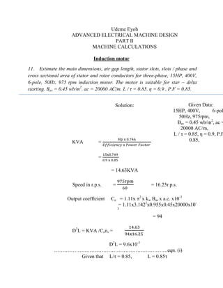
11. Estimate the main dimensions, air gap length, stator slots, slots / phase and
cross sectional area of stator and rotor conductors for three-phase, 15HP, 400V,
6-pole, 50Hz, 975 rpm induction motor. The motor is suitable for star – delta
starting. Bav = 0.45 wb/m2
. ac = 20000 AC/m. L / τ = 0.85. η = 0.9 , P.F = 0.85.
Solution:
KVA =
Hp x 0.746
𝐸𝑓𝑓𝑖𝑐𝑖𝑒𝑛𝑐𝑦 x 𝑃𝑜𝑤𝑒𝑟 𝐹𝑎𝑐𝑡𝑜𝑟
=
15x0.749
0.9 x 0.85
= 14.63KVA
Speed in r.p.s. =
975rpm
60
= 16.25r.p.s.
Output coefficient Co = 1.11x 2
x kw Bav x a.c. x10-3
= 1.11x3.1422
x0.955x0.45x20000x10-
3
= 94
D2
L = KVA /Cons =
14.63
94x16.25
D2
L = 9.6x10⁻³
………………………………………………………….eqn. (i)
Given that L/ = 0.85, L = 0.85
Given Data:
15HP, 400V, 6-pol
50Hz, 975rpm,
Bav = 0.45 wb/m2
, ac =
20000 AC/m,
L / τ = 0.85, η = 0.9, P.F
0.85,
Assumed Data:
Kw = 0.955, s = 4.5A/mm
b = 4.5A/mm2
2. But = D/p,
Hence, L = 0.85D/p,
L = 0.445D ………………….………………………………eqn. (ii)
Subst. (ii) in (i)
D3
0.445 = 9.6x10⁻³
D = 0.27m
Put D in eqn. (ii)
L = 0.445x0.27
= 0.12m
Air gap length = Lg = 0.2+2(DL)
= 0.2+2(0.27x0.12)
= 0.66mm
Stator slots Ss = slots/pole/phase
= 3x6x3
= 54
Stator Turns Ts can be determined from the e.m.f formula Es =
4.44kwfmTs
But m = BavDL/p = 0.45x 3.142 x0.27 x0.12/6
= 7.64x10⁻³
wb
Ts =Es/ 4.44kwfm
:.Ts = Es/4.44 x 0.955 x 50 x 7.64 x10-3
=247
Total Stator conductor = 3x2Ts = 3x2 x247 = 1482
Stator conductors/slot = Zss = 1482/Ss = 1482/54
= 27
Full load current Is = KVA x1000/3xEs
= 14.63 x1000/3x400
= 12.2A
Section of Stator conductor as = Is/s
3. Taking s to be 4A/mm2
,
Then, as = 12.2/4 = 3mm2
Taking Rotor Slots Sr to be 39
Rotor current Ib = 0.85x3x2xIsxTs/Sr
= 0.85x3x2x12.2x247/39
= 394.06A
Assuming Rotor current density, b = 4.5A/mm2
Then Rotor conductor area ab = Ib/ b
= 394.06/4.5= 87.6mm2
12. A 15 kW, three phase, 6 pole, 50 Hz, squirrel cage induction motor has the
following data, stator bore diameter = 0.32m, axial length of stator core =
0.125m, number of stator slots = 54, number of conductor / stator slot = 24,
current in each stator conductor = 17.5 A, full load P.F = 0.85 lag. Design a
suitable cage rotor giving number of rotor slots section of each bar and section
of each ring. The full speed is to be 950 rpm, use copper for rotor bar and end
ring conductor. Resistivity of copper is 0.02 Ωm.
Solution:
KVA= KW/ efficiency x Power factor
= 15 /0.85x0.85
= 20.8KVA
Ts =Es/ 4.44kwfm
or Slots x Zss/ 6
Given Data:
15KW, Ss = 54 ,Zss = 24,
poles, 50Hz,
Bav = 0.45 wb/m2
, P.F =
0.85,
= 0.02, Is =17.5A, 950rp
Assumed Data:
η = 85%, Kw = 0.955, Sb
39, b = 5A/mm2
4. = 54x24 /6x
= 216
Stator mmf Sm = 3xTs x Is
= 3 x 17.5 x 216
= 11340 A-T
Rator mmf Rm = 0.85x Sm
= 9639
Assuming Rotor Slots Sr = 39
But Rm = Ib xSr/2, :. Ib = 2xRm /Sr
= 9639 x 2/39
= 494.3A
Taking current density at Rotor periphery b = 5A/mm2
Area of each Rotor Copper Bar = ab = Ib/s
= 494.3/5 = 98.9mm2
End ring current Ie = Sr xIb/p
= 39x494.3/3.142x6
= 1022.6A
Area of end ring ae = Ie/s
= 1022.6/5 =204.5mm2
Resistance of Copper Bar rb = xL/ab
= 0.02 x 0.125/98.9
= 2.53x10⁻⁵
Total copper loss in all bars = Ib
2
x rb x Sr
= (2.53x10⁻⁵
)2
x 494.3 x 39
5. = 241W
Air gap length Lg = 0.2+2(DL)
= 0.2+2(0.32 x 0.125)
= 0.6mm
Diameter of Rotor Dr = D-2Lg
= 0.32 – (2x0.6)m
= 0.318m
Speed in r.p.s. (ns) = 950rpm/60 = 15.8r.p.s.
Checking for peripheral Velocity Va = Dns
= 3.142 x 0.32 x 15.8
= 15.92m/s (less than
permissible value for special rotors)