SlideShare a Scribd company logo
1 of 48
Download to read offline
PRESTRESSED CONCRETE STRUCTURES
Amlan K. Sengupta, PhD PE
Department of Civil Engineering
Indian Institute of Technology Madras
Module – 6: Calculation of Deflection and Crack Width
Lecture-29: Calculation of Deflection and Crack Width
Welcome back to prestressed concrete structures. This is the lecture of Module 6 on
calculation of deflection and crack width.
(Refer Slide Time 01:25)
In this lecture, we shall first study the calculation of deflection. Under that we shall learn
about the deflection due to gravity loads, deflection due to prestressing force, the
calculation of total deflection, the limits of deflection, determination of moment of inertia
and limits of span-to-effective depth ratio. Next, we shall study about the calculation of
crack width, under which we shall study the method of calculation and the limits of crack
width.
(Refer Slide Time 02:08)
First is the calculation of deflection. The deflection of a flexural member is calculated to
satisfy a limit state of serviceability. The deflection is calculated for the service loads.
Since a prestressed concrete member is smaller in depth than an equivalent reinforced
concrete member, the deflection of a prestressed concrete member tends to be larger. This
is one drawback, that if very shallow members are used then there may be deflection
problems. Hence the calculation of deflection becomes necessary, when the members are
shallow. We have to make sure that the deflection does not cause any problem in the
functioning of the member.
(Refer Slide Time 03:05)
The total deflection in a prestressed concrete member is a resultant of the upward
deflection due to prestressing force and downward deflection due to the gravity loads.
Thus, unlike reinforced concrete member here we have another component of deflection,
which is the deflection due to the prestressing force. For a simply supported beam, the
prestressing tendon provides an upward thrust to the member, which results in hogging
during the prestressing of the member. The total deflection is a summation of the upward
deflection due to the prestressing force and the downward deflection due to the gravity
loads.
(Refer Slide Time 03:55)
The deflection of a member is calculated at least for two cases. First is the short term
deflection at transfer. This deflection is due to prestressing force before long term losses,
and self-weight without the effect of creep and shrinkage of concrete. Thus, when the
prestress is transferred the member may have a resultant upward deflection (camber)
depending on the amount of prestressing force and the self weight of the member. It has
to be checked, whether the camber is too much during the prestressing operation or not. If
there is some finishing over the member then, it has to be checked whether there will be
any cracking on the finishes or not.
(Refer Slide Time 04:55)
The second case is the long term deflection at service loads. This deflection is due to
prestressing force after long term losses, and the permanent components of the gravity
loads, including the effects of creep and shrinkage. Thus, at service loads the deflection
has two components. One is due to the prestressing force after the long term losses, and
next is that due to the gravity loads. For the later, only the permanent components of the
gravity loads are considered in the long term deflections. The permanent components of
the gravity load include the dead load and sustained component of the live load.
Now, here comes an engineering judgment; that how much live load should be
considered to be sustained, that depends upon the analyst. In the permanent load, we are
including only the sustained part of the live load and not the total live load. If we are
interested in the total deflection, then we may include the deflection due to the additional
component of the live load as well. First, we shall see the calculation of deflection due to
gravity loads.
(Refer Slide Time 06:30)
The methods of calculation of deflection are covered under structural analysis. These
methods include the following: double integration method, moment‒area method,
conjugate beam method and principle of virtual work. A student should have studied
these methods in a course on structural analysis. In this lecture, we are not going into the
details of the evaluation of deflection based on these methods, but we shall consider the
end results from these methods. Numerical solutions schemes can be implemented in a
computer, based on the above methods.
(Refer Slide Time 07:23)
For members with prismatic cross-sections (that is, the cross-section is constant
throughout the span of a member), common support conditions and subjected to
conventional loading, the deflections are available in tables in text books. The
expressions of deflection (which is represented as ∆) for a few cases are provided here. I
is the moment of inertia of the section, and E is the modulus of elasticity of concrete.
What is the value of the moment of inertia we need to consider, that we shall discuss
later.
(Refer Slide Time 08:45)
In this figure, we can see two simply supported beams. For the top one, the beam is
subjected to a uniformly distributed load and the deflection at the centre is given as ∆ =
(5/384) × wL4
/EI. In the figure at the bottom, a beam is subjected to a point load at the
centre, and ∆ = PL3
/48EI.
(Refer Slide Time 09:10)
For a cantilever beam under a uniformly distributed load, the deflection at the end is
given as ∆ = wL4
/8EI. For a cantilever beam with a point load at the end, ∆ = PL3
/3EI. In
most of the prestressed concrete applications, the beams are simply supported. Hence, we
can use the standard expressions for simply supported beams, for calculating the
deflections due to the gravity loads. Next, we are calculating the deflections due to
prestressing force.
(Refer Slide Time 09:56)
The deflection due to prestressing force is calculated by the load-balancing method,
which is explained under “Analysis for Flexure”. Earlier, we had seen that there are three
methods of analysis of a prestressed member. First is based on the stress concept, the
second is based on the force concept and the third is based on the load-balancing method.
Now, the third method is used to calculate the deflection due to prestressing force. Here,
we shall see the expressions of the deflections due to prestressing force for the standard
cases. The deflection due to prestressing force is represented as ∆p.
(Refer Slide Time 10:48)
For a parabolic tendon with prestressing force P and eccentricity ‘e’ at the middle, there
is a uniform upward load, which is represented as wup. The span of the beam is equal to
L. The upward load is given as wup = 8Pe/L2
. Then, we can calculate the upward
deflection. ∆p = (5/384) wupL4
/EI. Thus, this is the expression of upward deflection of a
beam that is prestressed with a parabolic tendon.
(Refer Slide Time 11:40)
For a singly harped tendon, there is an upward force at the location of the harping, which
is denoted as Wup. Wup = 4Pe/L. Then ∆p = WupL3
/48EI. This is the expression of the
deflection of a beam that is prestressed with a singly harped tendon, and the harping point
is at the middle of the beam.
(Refer Slide Time 12:35)
Next, we are going on to the expression for a beam with a doubly harped tendon. Here,
the harping points are symmetric, and each harping point is at a distance aL from the
support. In this figure, we see that there are two upward forces, corresponding to the two
harping points, and each upward force is represented as Wup. Wup = Pe/aL. Then, ∆p = a(3
‒ 4a2
)WupL3
/24EI.
(Refer Slide Time 13:20)
Next, we are calculating the total deflection due to the prestressing force and the gravity
loads. As we said before, that the total deflection is calculated for the two cases: first, the
short term deflection at transfer, which we shall denote as ∆st, and the second is the long
term deflection under service loads, which is denoted as ∆lt.
(Refer Slide Time 13:55)
The short term deflection at transfer, ∆st = ‒∆Po + ∆sw. Here, ∆Po is the magnitude of
deflection due to the prestress at transfer (Po) which is before the long term losses. ∆sw is
the deflection due to the self-weight, which is downwards. Note, that the sign of the two
deflections are opposite. A negative sign has been placed for the deflection due to the
prestressing force, since this is upwards. Thus, in presence of the prestressing force, the
total deflection may become negative, if the value of ∆sw is numerically smaller than ∆po.
In that case, the beam will have a camber and it will deflect upwards.
(Refer Slide Time 15:10)
Now, we are calculating the long term deflection under service loads. The calculation of
long term deflection is difficult because the prestressing force and creep strain influence
each other. The creep of concrete is explained in the module of material properties.
(Refer Slide Time 15:35)
The creep of concrete is defined as the increase in deformation with time under constant
load. Due to the creep of concrete, the prestress in the tendon is reduced with time. This
is an important aspect in the calculation of long term deflections that the concrete
deforms with time due to the permanent load, and due to the deformation of the concrete
the prestressing force gets reduced. There is a loss in the prestressing force. Thus, creep
and the prestressing force influence each other. Hence, the exact calculation of long term
deflection gets difficult.
The creep was discussed in detail in the module of material properties. Here we are
having a quick review of how to measure the creep strain in concrete. The ultimate creep
strain is found to be proportional to the elastic strain. The ratio of the ultimate creep
strain to the elastic strain is called the creep coefficient θ.
(Refer Slide Time 16:53)
The creep coefficient θ, for three values of age of concrete at prestressing (termed as age
of loading, or age of prestressing) as per the code IS: 1343–1980 is given in the table. At
seven days of prestressing, the creep coefficient is 2.2; that means if the prestressing
force is transferred when the concrete age is seven days then the creep strain is 2.2 times
the elastic strain. If the prestress is transferred at twenty eight days, then the creep
coefficient is 1.6. Thus, the ultimate creep strain is reduced to 1.6 times the elastic strain.
Finally, if the transfer of prestress is at one year, then the creep coefficient is 1.1. That is,
the ultimate creep strain is 1.1 times the elastic strain.
In order to reduce the long term deflection, we should delay the application of the
prestressing force such that the concrete gains adequate strength, and the effect of creep
is reduced. In this table the only factor which has been considered in evaluating the creep
strain is the age of loading for the concrete. There are other factors which influence
creep. In case if more accurate evaluation of creep is necessary, with the time as a
variable, then we need to look into specialised literature.
(Refer Slide Time 18:46)
The following expression is a simplified form, where an average prestressing force is
considered to generate creep strain. The shrinkage strain is neglected.
∆lt = ‒∆Pe ‒(∆Po + ∆Pe)/2 × θ + (∆DL + ∆SL)(1 + θ) + ∆LL
This is an expression of the deflection due to long term loads, where we have considered
an average value of the prestressing force which causes the creep.
(Refer Slide Time 21:30)
To summarize the notations in the previous expression:
∆Po = magnitude of deflection due to Po, the prestress before long term losses;
∆Pe = magnitude of deflection due to Pe, where Pe is the effective prestress after long term
losses;
∆DL = deflection due to the dead load, including self-weight;
∆SL = deflection due to sustained live load;
∆LL = deflection due to additional live load.
(Refer Slide Time 22:00)
A more rigorous calculation of total deflection can be done using the incremental time
step method. It is a step-by-step procedure, where the change in prestressing force due to
creep and shrinkage strains is calculated at the end of each time step. The results at the
end of each time step are used for the next time step.
(Refer Slide Time 22:45)
This step-by-step procedure was suggested by the Precast/Prestressed Concrete Institute
(PCI) committee. The title of the paper is “Recommendations for Estimating Prestress
Losses”. It was published in the PCI Journal, Volume 20, Number 4, and in the month of
July to August, 1975. The pages are from 43 to 75. This method is called the General
Method of calculating the prestressing force with time.
(Refer Slide Time 23:38)
In this method, a minimum of four time steps are considered in the service life of a
prestressed member. The following table provides the definitions of the time steps.
(Refer Slide Time 24:30)
First, the time scale is discretised into four steps, and the discretization is based on the
variation of the prestressing force with time. The method suggests that at least a
minimum four times steps should be considered and those time steps are as follows. For a
pre-tensioned member, the beginning of the time step is the anchoring of the steel. For a
post-tensioned member, the beginning is the end of curing. The end of the first time step
is the age of prestressing. Thus, within this period for the pre-tensioned member there can
be some relaxation losses after the tension has been applied on the steel. For the post-
tensioned member, there will be some shrinkage in the concrete which is neglected in the
calculation of the loss of prestress. For the second time step, the beginning of the step is
the end of the first time step, and the end of the second step is thirty days after
prestressing or when subjected to superimposed load. Thus, the first one month after
prestressing is important in the variation of the prestressing force, and the creep and
shrinkage strains.
For the third time step, the beginning is the end of Step 2 and the end is one year of
service. The fourth time step begins at the end of Step 3 and ends at the end of service
life. Thus, these are the minimum four time steps that the committee recommended to
monitor the prestressing force with time considering the creep and shrinkage strains in
the concrete.
(Refer Slide Time 26:12)
The step-by-step procedure can be implemented in a computer program, where the
number of time steps can be increased. Thus, we may not stick to four time steps, we can
have even larger number of time steps, which can be implemented in a computer
program. In this method, we need more accurate expressions of the creep and shrinkage
strains, which are functions of time.
(Refer Slide Time 26:46)
Next, we are calculating the limits of deflection. Clause 19.3.1 of IS: 1343‒1980
specifies limits of deflection such that the efficiency of the structural element and the
appearance of the finishes or partitions, are not adversely affected. The limits of
deflection are summarized next.
(Refer Slide Time 27:07)
1) The total deflection due to all loads, including the effects of temperature, creep and
shrinkage, should not exceed span divided by 250.
(Refer Slide Time 27:40)
2) The next requirement is that the deflection after erection of partitions or application of
finishes, including the effects of temperature, creep and shrinkage, should not exceed
span divided by 350 or 20 mm, whichever is less. Thus, if there are partitions or finishes
we may need to calculate deflections before the finishes or partitions are applied, because
we are calculating the additional deflection after the partitions or finishes are placed.
3) The third limit is that if finishes are applied at the top of a beam, then the total upward
deflection due to the prestressing force should not exceed span divided by 300.
These are the limits that the code specifies. For special structures, additional limits may
be considered depending upon the situation. Next, we are moving on to the determination
of moment of inertia.
(Refer Slide Time 29:10)
For Type 1 and Type 2 members, since they are designed to be uncracked under service
loads, the gross moment of inertia which is represented as Ig can be used to calculate
deflections. That means, the moment of inertia can be calculated from the total section
and it can be substituted in the expressions of deflection.
(Refer Slide Time 29:40)
Type 3 members are expected to be cracked under service loads. Strictly, the gross
moment of inertia cannot be used in the calculations. IS: 1343 – 1980, Clause 22.6.2,
recommends the following:
(Refer Slide Time 30:00)
1) When the permanent load is less than or equal to 25% of the live load, the gross
moment of inertia can be used. If the permanent component of the live load is very small,
then most of the time the section will remain under compression. Hence we can use the
gross moment of inertia.
2) If the permanent component of the live load exceeds 25%, then the code recommends
that the span-to-effective depth ratio, which is denoted as L/d, should be limited to bypass
the calculation of deflection.
Thus, if the span-to-depth ratio is limited to a certain value, which we shall learn next,
then we can bypass the calculation of deflection, because it is considered that the
deflection will not be of any problem.
(Refer Slide Time 31:10)
If the L/d ratio exceeds the limit, then the gross moment of inertia can be used, when the
tensile stress under service loads is within the allowable value. The calculation of gross
moment of inertia is simpler as compared to an effective moment of inertia.
In reinforced concrete, we use an effective moment of inertia to consider the variation of
moment of inertia along the span. For prestressed concrete, even for a Type 3 member if
the tensile stress is limited to the allowable value, then we may use the gross moment of
inertia.
Next, we are learning about the limits of span-to-effective depth ratio.
(Refer Slide Time 32:10)
The calculation of deflection can be bypassed if the span-to-effective depth ratio, which
is represented as L/d, is within the specified limit. The limits of L/d ratio, as per Clause
22.6.2 of IS: 1343 ‒ 1980 are as follows. For span (L) less than 10 m, for cantilever
beams L/d should be less than 7; for simply supported beams the ratio should be less than
20; for continuous beams the ratio should be less than 26.
(Refer Slide Time 33:10)
If the span exceeds 10 m, then we have to modify these limits as follows. For simply
supported beams, L/d should be less than 20 × 10/L. For continuous beams, L/d should be
less than 26 × 10/L. Here, L is in meters. Deflection calculations are necessary for
cantilevers with L greater than 10 m.
Next, we are moving on to the second serviceability check, which is the calculation of
crack width.
(Refer Slide Time 34:10)
The crack width of a flexural member is calculated to satisfy a limit state of
serviceability. Among prestressed concrete members, there is cracking under service
loads only for Type 3 members. Hence the cracking and the calculation of crack width is
relevant only for Type 3 members.
We have learnt earlier that Type 1 member is designed such that, there is no tensile stress
in the member under service loads. Type 2 member is designed such that, there can be
tensile stress in the member but the tensile stress is less than the cracking stress at service
loads. For Type 3 member cracking is allowed, but it is limited by limiting the crack
width. Thus, the calculation of crack width is relevant only for Type 3 members and the
crack widths are calculated for the service loads.
(Refer Slide Time 35:15)
Type 3 members have regular reinforcing bars which are non-prestressed, in the tension
zone close to the surface, in addition to the prestressed tendons. This is to limit the crack
width and to distribute the cracking.
(Refer Slide Time 35:45)
The crack width is calculated for the flexural cracks. The flexural cracks start from the
tension face and propagate perpendicular to the axis of the member. This type of cracks is
mentioned in the module of “Analysis for Shear”. If these cracks are wide, it leads to
corrosion of the reinforcing bars and prestressed tendons. Also the appearance becomes
bad. The crack width calculation is related to the width of the flexural cracks.
(Refer Slide Time 36:30)
The surface crack width of a flexural crack depends on the following quantities:
1) Amount of prestress,
2) Tensile strength in the longitudinal bars,
3) Thickness of the concrete cover,
4) Diameter and spacing of longitudinal bars,
5) Depth of member and location of neutral axis,
6) Bond strength and
7) Tensile strength of concrete.
(Refer Slide Time 36:55)
The crack width calculation is a difficult process. There is a fracture mechanics based
approach to calculate the crack width. But the recommendations in reinforced concrete
design are simpler for our day-to-day use in design checks. We have to appreciate that the
crack width depends on several factors, and the expression provides only an estimate of
the crack width. When we are experimentally investigating the crack width, we may find
variations in the observed crack width.
(Refer Slide Time 37:50)
IS: 456 – 2000, Annex F, gives a simplified procedure to determine crack width. The
design surface crack width (which will be represented as Wcr) at a selected location in the
section with maximum moment, is given as follows. For that particular section, we can
select any location along the periphery in the tensile region.
Wcr = 3acr εm/ (1 + 2(acr ‒ Cmin)/(h ‒ x)
(Refer Slide Time 39:18)
To summarize the notations:
acr = shortest distance from the selected location on the surface to a longitudinal bar,
Cmin = minimum clear cover to the longitudinal bar,
h = total depth of the member,
x = depth of the neutral axis,
εm = average strain at the selected location.
The zone below the neutral axis is the zone under tension. Thus, h ‒ x is the depth of the
zone of concrete under tension.
We shall discuss later what is meant by an average. The values of Cmin and h are obtained
from the section of the member. Next, we need to calculate acr and then we need to
calculate x and εm.
(Refer Slide Time 40:15)
Evaluation of acr:
The location of the crack width calculation can be at the soffit or the sides of the beam.
The value of acr depends on the selected location. The following sketch shows the values
of acr at a bottom corner (A), at a point in the soffit of the beam (B) and at a point at the
side (C). For these three points, the distance to the nearest longitudinal bar has been
represented by acr. Thus, the value of acr can be found out from the design section, based
on the location of calculation of crack width.
(Refer Slide Time 41:35)
Usually, the crack width is calculated at a point in the soffit, which is equidistant from
two longitudinal bars. This point is the location of maximum estimated crack width.
Hence, first we calculate the crack width at the soffit, which is in between two
longitudinal bars.
In this sketch of the cross section of the beam, Cmin is the clear cover, s is the spacing of
the longitudinal bars, db is the diameter of the longitudinal bars, acr is the distance from
the point of investigation to the nearest longitudinal bar and dc is the effective cover to
the reinforcing bars.
(Refer Slide Time 42:45)
The value of acr is obtained from the following equation based on the Pythagorean
theorem. It is the radial distance from the point of investigation to the center of the
nearest bar.
acr = √[(s/2)2
+ dc
2
] ‒ (db/2)
In this expression,
db = diameter of a longitudinal bar
dc = effective cover = Cmin + db/2
s = center-to-centre spacing of longitudinal bars.
The values of db, dc and s are obtained from the section of the member. Thus, once the
member has been designed for flexure, these variables are available and we can calculate
the distance acr.
(Refer Slide Time 44:16)
Next, we are evaluating the depth of the neutral axis and the average strain at the level of
investigation of crack width. The values of x and εm are calculated based on a sectional
analysis under service loads.
(Refer Slide Time 44:45)
The sectional analysis should consider the tension carried by the uncracked concrete in
between two cracks. The stiffening of a member due to the tension carried by the
concrete is called the tension stiffening effect. The value of εm is considered to be an
average value over the span. This is a new concept which we are observing. For flexure,
usually we do a sectional analysis at the critical section, which is a cracked section. But
when we are trying to find out the crack width, if you do a cracked section analysis, then
the crack width is over estimated. The reason behind this is that, if we just do a cracked
section analysis then we are neglecting the effect of concrete, which is in between the
cracks. The concrete in between the cracks has some tensile strength, and that tensile
strength reduces the crack width if we just calculate it based on a cracked section. The
effect of tension in the concrete in between two cracks is called the tension stiffening
effect. It reduces the crack width, and it also reduces the deflection from the value
calculated based only on cracked section.
In this figure you can see that the cracked section is at the location of a crack, whereas
the uncracked concrete is in between two cracks, which helps the beam to reduce
deflection. The contribution of uncracked concrete is called the tension stiffening effect.
When we are calculating εm at the soffit of the beam, since εm various along the length of
the span, we are calculating an average value, which should include the tension stiffening
effect.
(Refer Slide Time 47:00)
IS: 456 - 2000 recommends two procedures for the sectional analysis, considering the
tension stiffening effect. The first one is a rigorous procedure with explicit calculation of
tension carried by the concrete.
(Refer Slide Time 47:20)
The second one is a simplified procedure based on the conventional analysis of a cracked
section, neglecting the tension carried by concrete. An approximate estimate of the
tension carried by the concrete is subsequently introduced.
Thus, IS: 456 gives us two procedures to do the sectional analysis to calculate x and εm.
The first one is a rigorous procedure, where we consider a section with tension in the
concrete below the neutral axis. The second procedure is the conventional cracked
section analysis, where we neglect any tension in the concrete below the neutral axis. But
then the strain is modified to take account of the tension in the concrete. In this lecture,
we shall explain the simpler procedure which is based on a conventional cracked section
analysis.
(Refer Slide Time 48:45)
For a rectangular zone under tension,
εm = ε1 ‒ [b (h ‒ x) (a ‒ x)]/[3 Es As (d ‒ x)]
For a prestressed member, EpAp + EsAs is substituted in place of EsAs. We shall
understand the notation of each of these terms in the next slide.
(Refer Slide Time 49:17)
In the above expression,
a = distance from the compression face to the location at which crack width is calculated,
which is same as h when the crack width is calculated at the soffit
b = width of the rectangular zone. In most of our applications we will have a rectangular
zone at the bottom and hence this formula will be applicable, where b is the width of the
rectangular zone.
d = effective depth of the longitudinal reinforcement, that means it is the effective depth
of the non-prestressed steel
As = area of non-prestressed reinforcement
Ap = area of prestressing steel.
(Refer Slide Time 50:10)
Es = modulus of elasticity of non-prestressed steel,
Ep = modulus of elasticity of prestressed steel.
All these variables are available from the section and the material properties of the beam.
The two variables ε1 and εs which are used in εm need to be calculated.
ε1 = strain at the selected location. For the soffit, it is the strain at the soffit. By similarity
of triangles, ε1 = εs(a ‒ x)/(d ‒ x).
εs = strain in the longitudinal reinforcement, based on the cracked section analysis.
(Refer Slide Time 51:14)
The cracked section analysis of a Type 3 member should be based on strain compatibility
of concrete and prestressing steel. The depth of neutral axis (x) can be calculated by a
trial and error procedure, till the equilibrium equations are satisfied. The equilibrium and
compatibility equations are provided here.
(Refer Slide Time 52:11)
The following sketch shows the beam cross section, strain profile, stress diagram and
force couples under service loads. The contribution of non-prestressed reinforcement is
also included.
(Refer Slide Time 52:30)
In this figure, we see that for a rectangular section b is the breadth, dp is the depth of the
prestressing steel, d is the depth of the non-prestressed reinforcement. In the strain
diagram εc is the strain in the concrete at the top, εs is the strain in the non-prestressed
steel and εdec is the strain at decompression. The total strain in the prestressing steel εp is
the strain in the concrete at the level of the prestressing steel plus εdec. The strain diagram
considers the strain compatibility of the concrete and the prestressing steel, at the level of
the prestressing steel. The stress diagram in concrete is linear. The maximum stress in
concrete is fc, and the stress in the prestressing steel and the non-prestressed steel are fp
and fs, respectively. The resultant compression C occurs at one-third the depth of the
neutral axis, and the tension are represented as Tp for the prestressing steel and Ts for the
non-prestressed steel.
(Refer Slide Time 54:10)
From the stress diagram and the force couples, we can write the expressions of the forces.
C = 0.5Ecεcxb, which is the area of the stress triangle.
Tp = ApEpεp
Ts = AsEsεs.
(Refer Slide Time 54:50)
The first equilibrium equation is the equilibrium of the axial forces.
ΣF = 0 ⇒ Tp + Ts = C
Here, we write the expressions of Tp, Ts and C. The value of x should be such that this
equation is satisfied.
(Refer Slide Time 55:12)
The second equilibrium equation is the moment equation.
ΣM = 0
Taking the moment about the prestressing steel, we have M is equal to Ts times the
distance between the prestressing and the non-prestressed steel, plus C times the distance
between the prestressing steel and the location of C. When we substitute the expressions
of Ts and C, we get an expression of the moment. The value of the moment should be
equal to the moment due to service loads. Thus, x should be such that we need to satisfy
both this equilibrium equations.
(Refer Slide Time 56:10)
Among the compatibility equations, the first equation relates the compatibility between
the prestressing steel and the concrete.
x/dp = εc/(εc + εp ‒ εdec)
The second equation is for the non-prestressed steel.
(d ‒ x)/x = εs/εc.
(Refer Slide Time 56:38)
The constitutive relationships have been considered in the expressions of C, Ts and Tp
and we have used the elastic relationships to calculate C, Ts and Tp from the respective
strains.
The equations have to be solved to evaluate x, which should be substituted in the
expressions of εm and Wcr, to calculate the crack width for a Type 3 member.
(Refer Slide Time 57:20)
The limits of crack width are as follows. Clause 19.3.2 of the code specifies the limits
such that the appearance and durability of the structure elements are not affected.
(Refer Slide Time 57:35)
The crack width should be less than 0.2 mm for moderate and mild environments, and 0.1
mm for severe environment. The types of environment are explained in Table 9,
Appendix A of IS: 1343 - 1980. Once we calculate the crack width, we should make sure
that the crack width is within the limit, depending on the environment the structure is in.
(Refer Slide Time 58:06)
Thus, in today’s lecture, we first went through the calculation of deflection. We knew the
deflections due to gravity loads; we learned about the deflections due to prestressing
force. Then, we studied how to calculate the total deflection, and the limits of deflection
the member needs to satisfy. We learned about the determination of moment of inertia. If
we satisfy the limit of span-to-effective depth ratio, then we can bypass the deflection
calculations.
Next, we studied the calculation of crack width. First we studied the method of
calculation and next, we found out the limits of crack width. The calculations of
deflection and the crack width help us to satisfy the limits state of serviceability.
Thank you.

More Related Content

What's hot

Analysis of continuous prestressed concrete
Analysis of continuous prestressed concreteAnalysis of continuous prestressed concrete
Analysis of continuous prestressed concreteSRAVANTHI mehar
 
Introduction to prestressed concrete
Introduction to prestressed concreteIntroduction to prestressed concrete
Introduction to prestressed concreteARULPANDIAN8
 
Losses in prestress [autosaved]
Losses in prestress [autosaved]Losses in prestress [autosaved]
Losses in prestress [autosaved]SHARIQUE AHMAD
 
Unit I Losses of prestress and deflection
Unit I Losses of prestress and deflectionUnit I Losses of prestress and deflection
Unit I Losses of prestress and deflectionSelvakumar Palanisamy
 
Cracking in Reinforced Concrete Flexural Members (by Robin)
Cracking in Reinforced Concrete Flexural Members (by Robin)Cracking in Reinforced Concrete Flexural Members (by Robin)
Cracking in Reinforced Concrete Flexural Members (by Robin)Shariful Haque Robin
 
Pre stressed concrete construction
Pre stressed concrete constructionPre stressed concrete construction
Pre stressed concrete constructionJenilPatel22
 
Loss of pre stress in pre-stressed concrete
Loss of pre stress in pre-stressed concrete Loss of pre stress in pre-stressed concrete
Loss of pre stress in pre-stressed concrete Abdulrahman Salah
 
Basic concept of pre-stressing
Basic concept of pre-stressingBasic concept of pre-stressing
Basic concept of pre-stressingManjunathKB11
 
Comparison of reinforced concrete and prestressed concrete
Comparison of reinforced concrete and prestressed concreteComparison of reinforced concrete and prestressed concrete
Comparison of reinforced concrete and prestressed concreteSpice Shuvo
 
Prestressed concrete baru
Prestressed concrete baruPrestressed concrete baru
Prestressed concrete baruKartina Sazali
 
Design of Prestressed Concrete - <topic>
Design of Prestressed Concrete  - <topic>Design of Prestressed Concrete  - <topic>
Design of Prestressed Concrete - <topic>S M Rahat Rahman
 
Introduction to prestressed concrete
Introduction to prestressed concreteIntroduction to prestressed concrete
Introduction to prestressed concrete9833356555
 
ANALYSIS & DESIGN ASPECTS OF PRE-STRESSED MEMBERS USING F.R.P. TENDONS
ANALYSIS & DESIGN ASPECTS OF PRE-STRESSED MEMBERS USING F.R.P. TENDONSANALYSIS & DESIGN ASPECTS OF PRE-STRESSED MEMBERS USING F.R.P. TENDONS
ANALYSIS & DESIGN ASPECTS OF PRE-STRESSED MEMBERS USING F.R.P. TENDONSGirish Singh
 
Prestressed concrete
Prestressed concretePrestressed concrete
Prestressed concreteRajat Nainwal
 
DYNAMIC RESPONSE OF SIMPLE SUPPORTED BEAM VIBRATED UNDER MOVING LOAD
DYNAMIC RESPONSE OF SIMPLE SUPPORTED BEAM VIBRATED UNDER MOVING LOAD DYNAMIC RESPONSE OF SIMPLE SUPPORTED BEAM VIBRATED UNDER MOVING LOAD
DYNAMIC RESPONSE OF SIMPLE SUPPORTED BEAM VIBRATED UNDER MOVING LOAD sadiq emad
 
Prestressed concrete structures
Prestressed concrete structuresPrestressed concrete structures
Prestressed concrete structuresRagu Varan
 

What's hot (20)

Analysis of continuous prestressed concrete
Analysis of continuous prestressed concreteAnalysis of continuous prestressed concrete
Analysis of continuous prestressed concrete
 
Introduction to prestressed concrete
Introduction to prestressed concreteIntroduction to prestressed concrete
Introduction to prestressed concrete
 
Losses in prestress [autosaved]
Losses in prestress [autosaved]Losses in prestress [autosaved]
Losses in prestress [autosaved]
 
Unit I Losses of prestress and deflection
Unit I Losses of prestress and deflectionUnit I Losses of prestress and deflection
Unit I Losses of prestress and deflection
 
Prestressing ppt
Prestressing pptPrestressing ppt
Prestressing ppt
 
Cracking in Reinforced Concrete Flexural Members (by Robin)
Cracking in Reinforced Concrete Flexural Members (by Robin)Cracking in Reinforced Concrete Flexural Members (by Robin)
Cracking in Reinforced Concrete Flexural Members (by Robin)
 
Pre stressed concrete construction
Pre stressed concrete constructionPre stressed concrete construction
Pre stressed concrete construction
 
Loss of pre stress in pre-stressed concrete
Loss of pre stress in pre-stressed concrete Loss of pre stress in pre-stressed concrete
Loss of pre stress in pre-stressed concrete
 
Prestressed composite beams
Prestressed composite beamsPrestressed composite beams
Prestressed composite beams
 
Basic concept of pre-stressing
Basic concept of pre-stressingBasic concept of pre-stressing
Basic concept of pre-stressing
 
Fundamentals of-psc-bridge
Fundamentals of-psc-bridgeFundamentals of-psc-bridge
Fundamentals of-psc-bridge
 
Comparison of reinforced concrete and prestressed concrete
Comparison of reinforced concrete and prestressed concreteComparison of reinforced concrete and prestressed concrete
Comparison of reinforced concrete and prestressed concrete
 
Prestressed concrete baru
Prestressed concrete baruPrestressed concrete baru
Prestressed concrete baru
 
Design of Prestressed Concrete - <topic>
Design of Prestressed Concrete  - <topic>Design of Prestressed Concrete  - <topic>
Design of Prestressed Concrete - <topic>
 
Introduction to prestressed concrete
Introduction to prestressed concreteIntroduction to prestressed concrete
Introduction to prestressed concrete
 
ANALYSIS & DESIGN ASPECTS OF PRE-STRESSED MEMBERS USING F.R.P. TENDONS
ANALYSIS & DESIGN ASPECTS OF PRE-STRESSED MEMBERS USING F.R.P. TENDONSANALYSIS & DESIGN ASPECTS OF PRE-STRESSED MEMBERS USING F.R.P. TENDONS
ANALYSIS & DESIGN ASPECTS OF PRE-STRESSED MEMBERS USING F.R.P. TENDONS
 
Prestressed concrete
Prestressed concretePrestressed concrete
Prestressed concrete
 
DYNAMIC RESPONSE OF SIMPLE SUPPORTED BEAM VIBRATED UNDER MOVING LOAD
DYNAMIC RESPONSE OF SIMPLE SUPPORTED BEAM VIBRATED UNDER MOVING LOAD DYNAMIC RESPONSE OF SIMPLE SUPPORTED BEAM VIBRATED UNDER MOVING LOAD
DYNAMIC RESPONSE OF SIMPLE SUPPORTED BEAM VIBRATED UNDER MOVING LOAD
 
Psc notes
Psc notesPsc notes
Psc notes
 
Prestressed concrete structures
Prestressed concrete structuresPrestressed concrete structures
Prestressed concrete structures
 

Similar to Dokumen.tips deflection prestressed-concrete

Deflections in PT elements pt structure for all pt slabs in civil industry.pdf
Deflections in PT elements pt structure for all pt slabs in civil industry.pdfDeflections in PT elements pt structure for all pt slabs in civil industry.pdf
Deflections in PT elements pt structure for all pt slabs in civil industry.pdfvijayvijay327286
 
Column and Strut .ppt
Column and Strut .pptColumn and Strut .ppt
Column and Strut .pptssuser77fe26
 
Strengthofmaterialsbyskmondal 130102103545-phpapp02
Strengthofmaterialsbyskmondal 130102103545-phpapp02Strengthofmaterialsbyskmondal 130102103545-phpapp02
Strengthofmaterialsbyskmondal 130102103545-phpapp02Priyabrata Behera
 
3-Flexural Analysis prestress concrete ppt
3-Flexural Analysis prestress concrete ppt3-Flexural Analysis prestress concrete ppt
3-Flexural Analysis prestress concrete ppt632k18BilalAhmad
 
Deflection of Beams.pptx......pptx
Deflection of Beams.pptx......pptxDeflection of Beams.pptx......pptx
Deflection of Beams.pptx......pptxKhalilBahrEldin
 
module 3 (Mechanics)
module 3 (Mechanics)module 3 (Mechanics)
module 3 (Mechanics)Nexus
 
Shear force and bending moment
Shear force and bending momentShear force and bending moment
Shear force and bending momenttalha022
 
Module-4 Notes.pdf
Module-4 Notes.pdfModule-4 Notes.pdf
Module-4 Notes.pdfatasubhani1
 
Influence line of reaction for determinate structure: determining maximum /mi...
Influence line of reaction for determinate structure: determining maximum /mi...Influence line of reaction for determinate structure: determining maximum /mi...
Influence line of reaction for determinate structure: determining maximum /mi...Rifat Hassan
 
Impulse momentum
Impulse momentumImpulse momentum
Impulse momentumEkeeda
 
Kinetics of particles impulse momentum method
Kinetics of particles impulse momentum methodKinetics of particles impulse momentum method
Kinetics of particles impulse momentum methodEkeeda
 
12. kinetics of particles impulse momentum method
12. kinetics of particles impulse momentum method12. kinetics of particles impulse momentum method
12. kinetics of particles impulse momentum methodEkeeda
 
Hysteresis models otani
Hysteresis models otaniHysteresis models otani
Hysteresis models otaniManuel Miranda
 
B Ending Moments And Shearing Forces In Beams2
B Ending Moments And Shearing Forces In Beams2B Ending Moments And Shearing Forces In Beams2
B Ending Moments And Shearing Forces In Beams2Amr Hamed
 
Shear and Bending Moment in Beams
Shear and Bending Moment in BeamsShear and Bending Moment in Beams
Shear and Bending Moment in BeamsAmr Hamed
 
Bendingmomentsandshearingforcesinbeams2 100114165451-phpapp01
Bendingmomentsandshearingforcesinbeams2 100114165451-phpapp01Bendingmomentsandshearingforcesinbeams2 100114165451-phpapp01
Bendingmomentsandshearingforcesinbeams2 100114165451-phpapp01Aero Mohamed
 

Similar to Dokumen.tips deflection prestressed-concrete (20)

Deflections in PT elements pt structure for all pt slabs in civil industry.pdf
Deflections in PT elements pt structure for all pt slabs in civil industry.pdfDeflections in PT elements pt structure for all pt slabs in civil industry.pdf
Deflections in PT elements pt structure for all pt slabs in civil industry.pdf
 
Plastic bottle analysis
Plastic bottle analysisPlastic bottle analysis
Plastic bottle analysis
 
Column and Strut .ppt
Column and Strut .pptColumn and Strut .ppt
Column and Strut .ppt
 
Strengthofmaterialsbyskmondal 130102103545-phpapp02
Strengthofmaterialsbyskmondal 130102103545-phpapp02Strengthofmaterialsbyskmondal 130102103545-phpapp02
Strengthofmaterialsbyskmondal 130102103545-phpapp02
 
3-Flexural Analysis prestress concrete ppt
3-Flexural Analysis prestress concrete ppt3-Flexural Analysis prestress concrete ppt
3-Flexural Analysis prestress concrete ppt
 
Megha.pdf
Megha.pdfMegha.pdf
Megha.pdf
 
Deflection of Beams.pptx......pptx
Deflection of Beams.pptx......pptxDeflection of Beams.pptx......pptx
Deflection of Beams.pptx......pptx
 
module 3 (Mechanics)
module 3 (Mechanics)module 3 (Mechanics)
module 3 (Mechanics)
 
Columns
ColumnsColumns
Columns
 
Shear force and bending moment
Shear force and bending momentShear force and bending moment
Shear force and bending moment
 
Module-4 Notes.pdf
Module-4 Notes.pdfModule-4 Notes.pdf
Module-4 Notes.pdf
 
Influence line of reaction for determinate structure: determining maximum /mi...
Influence line of reaction for determinate structure: determining maximum /mi...Influence line of reaction for determinate structure: determining maximum /mi...
Influence line of reaction for determinate structure: determining maximum /mi...
 
Structures and Materials- Section 3 Stress-Strain Relationships
Structures and Materials- Section 3 Stress-Strain RelationshipsStructures and Materials- Section 3 Stress-Strain Relationships
Structures and Materials- Section 3 Stress-Strain Relationships
 
Impulse momentum
Impulse momentumImpulse momentum
Impulse momentum
 
Kinetics of particles impulse momentum method
Kinetics of particles impulse momentum methodKinetics of particles impulse momentum method
Kinetics of particles impulse momentum method
 
12. kinetics of particles impulse momentum method
12. kinetics of particles impulse momentum method12. kinetics of particles impulse momentum method
12. kinetics of particles impulse momentum method
 
Hysteresis models otani
Hysteresis models otaniHysteresis models otani
Hysteresis models otani
 
B Ending Moments And Shearing Forces In Beams2
B Ending Moments And Shearing Forces In Beams2B Ending Moments And Shearing Forces In Beams2
B Ending Moments And Shearing Forces In Beams2
 
Shear and Bending Moment in Beams
Shear and Bending Moment in BeamsShear and Bending Moment in Beams
Shear and Bending Moment in Beams
 
Bendingmomentsandshearingforcesinbeams2 100114165451-phpapp01
Bendingmomentsandshearingforcesinbeams2 100114165451-phpapp01Bendingmomentsandshearingforcesinbeams2 100114165451-phpapp01
Bendingmomentsandshearingforcesinbeams2 100114165451-phpapp01
 

Recently uploaded

VIP Call Girls Service Hitech City Hyderabad Call +91-8250192130
VIP Call Girls Service Hitech City Hyderabad Call +91-8250192130VIP Call Girls Service Hitech City Hyderabad Call +91-8250192130
VIP Call Girls Service Hitech City Hyderabad Call +91-8250192130Suhani Kapoor
 
Structural Analysis and Design of Foundations: A Comprehensive Handbook for S...
Structural Analysis and Design of Foundations: A Comprehensive Handbook for S...Structural Analysis and Design of Foundations: A Comprehensive Handbook for S...
Structural Analysis and Design of Foundations: A Comprehensive Handbook for S...Dr.Costas Sachpazis
 
Sheet Pile Wall Design and Construction: A Practical Guide for Civil Engineer...
Sheet Pile Wall Design and Construction: A Practical Guide for Civil Engineer...Sheet Pile Wall Design and Construction: A Practical Guide for Civil Engineer...
Sheet Pile Wall Design and Construction: A Practical Guide for Civil Engineer...Dr.Costas Sachpazis
 
High Profile Call Girls Nagpur Meera Call 7001035870 Meet With Nagpur Escorts
High Profile Call Girls Nagpur Meera Call 7001035870 Meet With Nagpur EscortsHigh Profile Call Girls Nagpur Meera Call 7001035870 Meet With Nagpur Escorts
High Profile Call Girls Nagpur Meera Call 7001035870 Meet With Nagpur EscortsCall Girls in Nagpur High Profile
 
(RIA) Call Girls Bhosari ( 7001035870 ) HI-Fi Pune Escorts Service
(RIA) Call Girls Bhosari ( 7001035870 ) HI-Fi Pune Escorts Service(RIA) Call Girls Bhosari ( 7001035870 ) HI-Fi Pune Escorts Service
(RIA) Call Girls Bhosari ( 7001035870 ) HI-Fi Pune Escorts Serviceranjana rawat
 
Introduction to Multiple Access Protocol.pptx
Introduction to Multiple Access Protocol.pptxIntroduction to Multiple Access Protocol.pptx
Introduction to Multiple Access Protocol.pptxupamatechverse
 
IMPLICATIONS OF THE ABOVE HOLISTIC UNDERSTANDING OF HARMONY ON PROFESSIONAL E...
IMPLICATIONS OF THE ABOVE HOLISTIC UNDERSTANDING OF HARMONY ON PROFESSIONAL E...IMPLICATIONS OF THE ABOVE HOLISTIC UNDERSTANDING OF HARMONY ON PROFESSIONAL E...
IMPLICATIONS OF THE ABOVE HOLISTIC UNDERSTANDING OF HARMONY ON PROFESSIONAL E...RajaP95
 
Extrusion Processes and Their Limitations
Extrusion Processes and Their LimitationsExtrusion Processes and Their Limitations
Extrusion Processes and Their Limitations120cr0395
 
Call Girls in Nagpur Suman Call 7001035870 Meet With Nagpur Escorts
Call Girls in Nagpur Suman Call 7001035870 Meet With Nagpur EscortsCall Girls in Nagpur Suman Call 7001035870 Meet With Nagpur Escorts
Call Girls in Nagpur Suman Call 7001035870 Meet With Nagpur EscortsCall Girls in Nagpur High Profile
 
(ANVI) Koregaon Park Call Girls Just Call 7001035870 [ Cash on Delivery ] Pun...
(ANVI) Koregaon Park Call Girls Just Call 7001035870 [ Cash on Delivery ] Pun...(ANVI) Koregaon Park Call Girls Just Call 7001035870 [ Cash on Delivery ] Pun...
(ANVI) Koregaon Park Call Girls Just Call 7001035870 [ Cash on Delivery ] Pun...ranjana rawat
 
UNIT - IV - Air Compressors and its Performance
UNIT - IV - Air Compressors and its PerformanceUNIT - IV - Air Compressors and its Performance
UNIT - IV - Air Compressors and its Performancesivaprakash250
 
KubeKraft presentation @CloudNativeHooghly
KubeKraft presentation @CloudNativeHooghlyKubeKraft presentation @CloudNativeHooghly
KubeKraft presentation @CloudNativeHooghlysanyuktamishra911
 
Coefficient of Thermal Expansion and their Importance.pptx
Coefficient of Thermal Expansion and their Importance.pptxCoefficient of Thermal Expansion and their Importance.pptx
Coefficient of Thermal Expansion and their Importance.pptxAsutosh Ranjan
 
Booking open Available Pune Call Girls Koregaon Park 6297143586 Call Hot Ind...
Booking open Available Pune Call Girls Koregaon Park  6297143586 Call Hot Ind...Booking open Available Pune Call Girls Koregaon Park  6297143586 Call Hot Ind...
Booking open Available Pune Call Girls Koregaon Park 6297143586 Call Hot Ind...Call Girls in Nagpur High Profile
 
MANUFACTURING PROCESS-II UNIT-2 LATHE MACHINE
MANUFACTURING PROCESS-II UNIT-2 LATHE MACHINEMANUFACTURING PROCESS-II UNIT-2 LATHE MACHINE
MANUFACTURING PROCESS-II UNIT-2 LATHE MACHINESIVASHANKAR N
 
Introduction to IEEE STANDARDS and its different types.pptx
Introduction to IEEE STANDARDS and its different types.pptxIntroduction to IEEE STANDARDS and its different types.pptx
Introduction to IEEE STANDARDS and its different types.pptxupamatechverse
 
(PRIYA) Rajgurunagar Call Girls Just Call 7001035870 [ Cash on Delivery ] Pun...
(PRIYA) Rajgurunagar Call Girls Just Call 7001035870 [ Cash on Delivery ] Pun...(PRIYA) Rajgurunagar Call Girls Just Call 7001035870 [ Cash on Delivery ] Pun...
(PRIYA) Rajgurunagar Call Girls Just Call 7001035870 [ Cash on Delivery ] Pun...ranjana rawat
 
Software Development Life Cycle By Team Orange (Dept. of Pharmacy)
Software Development Life Cycle By  Team Orange (Dept. of Pharmacy)Software Development Life Cycle By  Team Orange (Dept. of Pharmacy)
Software Development Life Cycle By Team Orange (Dept. of Pharmacy)Suman Mia
 
The Most Attractive Pune Call Girls Budhwar Peth 8250192130 Will You Miss Thi...
The Most Attractive Pune Call Girls Budhwar Peth 8250192130 Will You Miss Thi...The Most Attractive Pune Call Girls Budhwar Peth 8250192130 Will You Miss Thi...
The Most Attractive Pune Call Girls Budhwar Peth 8250192130 Will You Miss Thi...ranjana rawat
 

Recently uploaded (20)

VIP Call Girls Service Hitech City Hyderabad Call +91-8250192130
VIP Call Girls Service Hitech City Hyderabad Call +91-8250192130VIP Call Girls Service Hitech City Hyderabad Call +91-8250192130
VIP Call Girls Service Hitech City Hyderabad Call +91-8250192130
 
Structural Analysis and Design of Foundations: A Comprehensive Handbook for S...
Structural Analysis and Design of Foundations: A Comprehensive Handbook for S...Structural Analysis and Design of Foundations: A Comprehensive Handbook for S...
Structural Analysis and Design of Foundations: A Comprehensive Handbook for S...
 
Sheet Pile Wall Design and Construction: A Practical Guide for Civil Engineer...
Sheet Pile Wall Design and Construction: A Practical Guide for Civil Engineer...Sheet Pile Wall Design and Construction: A Practical Guide for Civil Engineer...
Sheet Pile Wall Design and Construction: A Practical Guide for Civil Engineer...
 
High Profile Call Girls Nagpur Meera Call 7001035870 Meet With Nagpur Escorts
High Profile Call Girls Nagpur Meera Call 7001035870 Meet With Nagpur EscortsHigh Profile Call Girls Nagpur Meera Call 7001035870 Meet With Nagpur Escorts
High Profile Call Girls Nagpur Meera Call 7001035870 Meet With Nagpur Escorts
 
(RIA) Call Girls Bhosari ( 7001035870 ) HI-Fi Pune Escorts Service
(RIA) Call Girls Bhosari ( 7001035870 ) HI-Fi Pune Escorts Service(RIA) Call Girls Bhosari ( 7001035870 ) HI-Fi Pune Escorts Service
(RIA) Call Girls Bhosari ( 7001035870 ) HI-Fi Pune Escorts Service
 
Introduction to Multiple Access Protocol.pptx
Introduction to Multiple Access Protocol.pptxIntroduction to Multiple Access Protocol.pptx
Introduction to Multiple Access Protocol.pptx
 
IMPLICATIONS OF THE ABOVE HOLISTIC UNDERSTANDING OF HARMONY ON PROFESSIONAL E...
IMPLICATIONS OF THE ABOVE HOLISTIC UNDERSTANDING OF HARMONY ON PROFESSIONAL E...IMPLICATIONS OF THE ABOVE HOLISTIC UNDERSTANDING OF HARMONY ON PROFESSIONAL E...
IMPLICATIONS OF THE ABOVE HOLISTIC UNDERSTANDING OF HARMONY ON PROFESSIONAL E...
 
Extrusion Processes and Their Limitations
Extrusion Processes and Their LimitationsExtrusion Processes and Their Limitations
Extrusion Processes and Their Limitations
 
Call Girls in Nagpur Suman Call 7001035870 Meet With Nagpur Escorts
Call Girls in Nagpur Suman Call 7001035870 Meet With Nagpur EscortsCall Girls in Nagpur Suman Call 7001035870 Meet With Nagpur Escorts
Call Girls in Nagpur Suman Call 7001035870 Meet With Nagpur Escorts
 
Roadmap to Membership of RICS - Pathways and Routes
Roadmap to Membership of RICS - Pathways and RoutesRoadmap to Membership of RICS - Pathways and Routes
Roadmap to Membership of RICS - Pathways and Routes
 
(ANVI) Koregaon Park Call Girls Just Call 7001035870 [ Cash on Delivery ] Pun...
(ANVI) Koregaon Park Call Girls Just Call 7001035870 [ Cash on Delivery ] Pun...(ANVI) Koregaon Park Call Girls Just Call 7001035870 [ Cash on Delivery ] Pun...
(ANVI) Koregaon Park Call Girls Just Call 7001035870 [ Cash on Delivery ] Pun...
 
UNIT - IV - Air Compressors and its Performance
UNIT - IV - Air Compressors and its PerformanceUNIT - IV - Air Compressors and its Performance
UNIT - IV - Air Compressors and its Performance
 
KubeKraft presentation @CloudNativeHooghly
KubeKraft presentation @CloudNativeHooghlyKubeKraft presentation @CloudNativeHooghly
KubeKraft presentation @CloudNativeHooghly
 
Coefficient of Thermal Expansion and their Importance.pptx
Coefficient of Thermal Expansion and their Importance.pptxCoefficient of Thermal Expansion and their Importance.pptx
Coefficient of Thermal Expansion and their Importance.pptx
 
Booking open Available Pune Call Girls Koregaon Park 6297143586 Call Hot Ind...
Booking open Available Pune Call Girls Koregaon Park  6297143586 Call Hot Ind...Booking open Available Pune Call Girls Koregaon Park  6297143586 Call Hot Ind...
Booking open Available Pune Call Girls Koregaon Park 6297143586 Call Hot Ind...
 
MANUFACTURING PROCESS-II UNIT-2 LATHE MACHINE
MANUFACTURING PROCESS-II UNIT-2 LATHE MACHINEMANUFACTURING PROCESS-II UNIT-2 LATHE MACHINE
MANUFACTURING PROCESS-II UNIT-2 LATHE MACHINE
 
Introduction to IEEE STANDARDS and its different types.pptx
Introduction to IEEE STANDARDS and its different types.pptxIntroduction to IEEE STANDARDS and its different types.pptx
Introduction to IEEE STANDARDS and its different types.pptx
 
(PRIYA) Rajgurunagar Call Girls Just Call 7001035870 [ Cash on Delivery ] Pun...
(PRIYA) Rajgurunagar Call Girls Just Call 7001035870 [ Cash on Delivery ] Pun...(PRIYA) Rajgurunagar Call Girls Just Call 7001035870 [ Cash on Delivery ] Pun...
(PRIYA) Rajgurunagar Call Girls Just Call 7001035870 [ Cash on Delivery ] Pun...
 
Software Development Life Cycle By Team Orange (Dept. of Pharmacy)
Software Development Life Cycle By  Team Orange (Dept. of Pharmacy)Software Development Life Cycle By  Team Orange (Dept. of Pharmacy)
Software Development Life Cycle By Team Orange (Dept. of Pharmacy)
 
The Most Attractive Pune Call Girls Budhwar Peth 8250192130 Will You Miss Thi...
The Most Attractive Pune Call Girls Budhwar Peth 8250192130 Will You Miss Thi...The Most Attractive Pune Call Girls Budhwar Peth 8250192130 Will You Miss Thi...
The Most Attractive Pune Call Girls Budhwar Peth 8250192130 Will You Miss Thi...
 

Dokumen.tips deflection prestressed-concrete

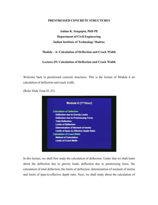
  • 1. PRESTRESSED CONCRETE STRUCTURES Amlan K. Sengupta, PhD PE Department of Civil Engineering Indian Institute of Technology Madras Module – 6: Calculation of Deflection and Crack Width Lecture-29: Calculation of Deflection and Crack Width Welcome back to prestressed concrete structures. This is the lecture of Module 6 on calculation of deflection and crack width. (Refer Slide Time 01:25) In this lecture, we shall first study the calculation of deflection. Under that we shall learn about the deflection due to gravity loads, deflection due to prestressing force, the calculation of total deflection, the limits of deflection, determination of moment of inertia and limits of span-to-effective depth ratio. Next, we shall study about the calculation of
  • 2. crack width, under which we shall study the method of calculation and the limits of crack width. (Refer Slide Time 02:08) First is the calculation of deflection. The deflection of a flexural member is calculated to satisfy a limit state of serviceability. The deflection is calculated for the service loads. Since a prestressed concrete member is smaller in depth than an equivalent reinforced concrete member, the deflection of a prestressed concrete member tends to be larger. This is one drawback, that if very shallow members are used then there may be deflection problems. Hence the calculation of deflection becomes necessary, when the members are shallow. We have to make sure that the deflection does not cause any problem in the functioning of the member.
  • 3. (Refer Slide Time 03:05) The total deflection in a prestressed concrete member is a resultant of the upward deflection due to prestressing force and downward deflection due to the gravity loads. Thus, unlike reinforced concrete member here we have another component of deflection, which is the deflection due to the prestressing force. For a simply supported beam, the prestressing tendon provides an upward thrust to the member, which results in hogging during the prestressing of the member. The total deflection is a summation of the upward deflection due to the prestressing force and the downward deflection due to the gravity loads.
  • 4. (Refer Slide Time 03:55) The deflection of a member is calculated at least for two cases. First is the short term deflection at transfer. This deflection is due to prestressing force before long term losses, and self-weight without the effect of creep and shrinkage of concrete. Thus, when the prestress is transferred the member may have a resultant upward deflection (camber) depending on the amount of prestressing force and the self weight of the member. It has to be checked, whether the camber is too much during the prestressing operation or not. If there is some finishing over the member then, it has to be checked whether there will be any cracking on the finishes or not.
  • 5. (Refer Slide Time 04:55) The second case is the long term deflection at service loads. This deflection is due to prestressing force after long term losses, and the permanent components of the gravity loads, including the effects of creep and shrinkage. Thus, at service loads the deflection has two components. One is due to the prestressing force after the long term losses, and next is that due to the gravity loads. For the later, only the permanent components of the gravity loads are considered in the long term deflections. The permanent components of the gravity load include the dead load and sustained component of the live load. Now, here comes an engineering judgment; that how much live load should be considered to be sustained, that depends upon the analyst. In the permanent load, we are including only the sustained part of the live load and not the total live load. If we are interested in the total deflection, then we may include the deflection due to the additional component of the live load as well. First, we shall see the calculation of deflection due to gravity loads.
  • 6. (Refer Slide Time 06:30) The methods of calculation of deflection are covered under structural analysis. These methods include the following: double integration method, moment‒area method, conjugate beam method and principle of virtual work. A student should have studied these methods in a course on structural analysis. In this lecture, we are not going into the details of the evaluation of deflection based on these methods, but we shall consider the end results from these methods. Numerical solutions schemes can be implemented in a computer, based on the above methods.
  • 7. (Refer Slide Time 07:23) For members with prismatic cross-sections (that is, the cross-section is constant throughout the span of a member), common support conditions and subjected to conventional loading, the deflections are available in tables in text books. The expressions of deflection (which is represented as ∆) for a few cases are provided here. I is the moment of inertia of the section, and E is the modulus of elasticity of concrete. What is the value of the moment of inertia we need to consider, that we shall discuss later.
  • 8. (Refer Slide Time 08:45) In this figure, we can see two simply supported beams. For the top one, the beam is subjected to a uniformly distributed load and the deflection at the centre is given as ∆ = (5/384) × wL4 /EI. In the figure at the bottom, a beam is subjected to a point load at the centre, and ∆ = PL3 /48EI. (Refer Slide Time 09:10)
  • 9. For a cantilever beam under a uniformly distributed load, the deflection at the end is given as ∆ = wL4 /8EI. For a cantilever beam with a point load at the end, ∆ = PL3 /3EI. In most of the prestressed concrete applications, the beams are simply supported. Hence, we can use the standard expressions for simply supported beams, for calculating the deflections due to the gravity loads. Next, we are calculating the deflections due to prestressing force. (Refer Slide Time 09:56) The deflection due to prestressing force is calculated by the load-balancing method, which is explained under “Analysis for Flexure”. Earlier, we had seen that there are three methods of analysis of a prestressed member. First is based on the stress concept, the second is based on the force concept and the third is based on the load-balancing method. Now, the third method is used to calculate the deflection due to prestressing force. Here, we shall see the expressions of the deflections due to prestressing force for the standard cases. The deflection due to prestressing force is represented as ∆p.
  • 10. (Refer Slide Time 10:48) For a parabolic tendon with prestressing force P and eccentricity ‘e’ at the middle, there is a uniform upward load, which is represented as wup. The span of the beam is equal to L. The upward load is given as wup = 8Pe/L2 . Then, we can calculate the upward deflection. ∆p = (5/384) wupL4 /EI. Thus, this is the expression of upward deflection of a beam that is prestressed with a parabolic tendon. (Refer Slide Time 11:40)
  • 11. For a singly harped tendon, there is an upward force at the location of the harping, which is denoted as Wup. Wup = 4Pe/L. Then ∆p = WupL3 /48EI. This is the expression of the deflection of a beam that is prestressed with a singly harped tendon, and the harping point is at the middle of the beam. (Refer Slide Time 12:35) Next, we are going on to the expression for a beam with a doubly harped tendon. Here, the harping points are symmetric, and each harping point is at a distance aL from the support. In this figure, we see that there are two upward forces, corresponding to the two harping points, and each upward force is represented as Wup. Wup = Pe/aL. Then, ∆p = a(3 ‒ 4a2 )WupL3 /24EI.
  • 12. (Refer Slide Time 13:20) Next, we are calculating the total deflection due to the prestressing force and the gravity loads. As we said before, that the total deflection is calculated for the two cases: first, the short term deflection at transfer, which we shall denote as ∆st, and the second is the long term deflection under service loads, which is denoted as ∆lt. (Refer Slide Time 13:55)
  • 13. The short term deflection at transfer, ∆st = ‒∆Po + ∆sw. Here, ∆Po is the magnitude of deflection due to the prestress at transfer (Po) which is before the long term losses. ∆sw is the deflection due to the self-weight, which is downwards. Note, that the sign of the two deflections are opposite. A negative sign has been placed for the deflection due to the prestressing force, since this is upwards. Thus, in presence of the prestressing force, the total deflection may become negative, if the value of ∆sw is numerically smaller than ∆po. In that case, the beam will have a camber and it will deflect upwards. (Refer Slide Time 15:10) Now, we are calculating the long term deflection under service loads. The calculation of long term deflection is difficult because the prestressing force and creep strain influence each other. The creep of concrete is explained in the module of material properties.
  • 14. (Refer Slide Time 15:35) The creep of concrete is defined as the increase in deformation with time under constant load. Due to the creep of concrete, the prestress in the tendon is reduced with time. This is an important aspect in the calculation of long term deflections that the concrete deforms with time due to the permanent load, and due to the deformation of the concrete the prestressing force gets reduced. There is a loss in the prestressing force. Thus, creep and the prestressing force influence each other. Hence, the exact calculation of long term deflection gets difficult. The creep was discussed in detail in the module of material properties. Here we are having a quick review of how to measure the creep strain in concrete. The ultimate creep strain is found to be proportional to the elastic strain. The ratio of the ultimate creep strain to the elastic strain is called the creep coefficient θ.
  • 15. (Refer Slide Time 16:53) The creep coefficient θ, for three values of age of concrete at prestressing (termed as age of loading, or age of prestressing) as per the code IS: 1343–1980 is given in the table. At seven days of prestressing, the creep coefficient is 2.2; that means if the prestressing force is transferred when the concrete age is seven days then the creep strain is 2.2 times the elastic strain. If the prestress is transferred at twenty eight days, then the creep coefficient is 1.6. Thus, the ultimate creep strain is reduced to 1.6 times the elastic strain. Finally, if the transfer of prestress is at one year, then the creep coefficient is 1.1. That is, the ultimate creep strain is 1.1 times the elastic strain. In order to reduce the long term deflection, we should delay the application of the prestressing force such that the concrete gains adequate strength, and the effect of creep is reduced. In this table the only factor which has been considered in evaluating the creep strain is the age of loading for the concrete. There are other factors which influence creep. In case if more accurate evaluation of creep is necessary, with the time as a variable, then we need to look into specialised literature.
  • 16. (Refer Slide Time 18:46) The following expression is a simplified form, where an average prestressing force is considered to generate creep strain. The shrinkage strain is neglected. ∆lt = ‒∆Pe ‒(∆Po + ∆Pe)/2 × θ + (∆DL + ∆SL)(1 + θ) + ∆LL This is an expression of the deflection due to long term loads, where we have considered an average value of the prestressing force which causes the creep.
  • 17. (Refer Slide Time 21:30) To summarize the notations in the previous expression: ∆Po = magnitude of deflection due to Po, the prestress before long term losses; ∆Pe = magnitude of deflection due to Pe, where Pe is the effective prestress after long term losses; ∆DL = deflection due to the dead load, including self-weight; ∆SL = deflection due to sustained live load; ∆LL = deflection due to additional live load.
  • 18. (Refer Slide Time 22:00) A more rigorous calculation of total deflection can be done using the incremental time step method. It is a step-by-step procedure, where the change in prestressing force due to creep and shrinkage strains is calculated at the end of each time step. The results at the end of each time step are used for the next time step. (Refer Slide Time 22:45)
  • 19. This step-by-step procedure was suggested by the Precast/Prestressed Concrete Institute (PCI) committee. The title of the paper is “Recommendations for Estimating Prestress Losses”. It was published in the PCI Journal, Volume 20, Number 4, and in the month of July to August, 1975. The pages are from 43 to 75. This method is called the General Method of calculating the prestressing force with time. (Refer Slide Time 23:38) In this method, a minimum of four time steps are considered in the service life of a prestressed member. The following table provides the definitions of the time steps.
  • 20. (Refer Slide Time 24:30) First, the time scale is discretised into four steps, and the discretization is based on the variation of the prestressing force with time. The method suggests that at least a minimum four times steps should be considered and those time steps are as follows. For a pre-tensioned member, the beginning of the time step is the anchoring of the steel. For a post-tensioned member, the beginning is the end of curing. The end of the first time step is the age of prestressing. Thus, within this period for the pre-tensioned member there can be some relaxation losses after the tension has been applied on the steel. For the post- tensioned member, there will be some shrinkage in the concrete which is neglected in the calculation of the loss of prestress. For the second time step, the beginning of the step is the end of the first time step, and the end of the second step is thirty days after prestressing or when subjected to superimposed load. Thus, the first one month after prestressing is important in the variation of the prestressing force, and the creep and shrinkage strains. For the third time step, the beginning is the end of Step 2 and the end is one year of service. The fourth time step begins at the end of Step 3 and ends at the end of service life. Thus, these are the minimum four time steps that the committee recommended to monitor the prestressing force with time considering the creep and shrinkage strains in the concrete.
  • 21. (Refer Slide Time 26:12) The step-by-step procedure can be implemented in a computer program, where the number of time steps can be increased. Thus, we may not stick to four time steps, we can have even larger number of time steps, which can be implemented in a computer program. In this method, we need more accurate expressions of the creep and shrinkage strains, which are functions of time. (Refer Slide Time 26:46)
  • 22. Next, we are calculating the limits of deflection. Clause 19.3.1 of IS: 1343‒1980 specifies limits of deflection such that the efficiency of the structural element and the appearance of the finishes or partitions, are not adversely affected. The limits of deflection are summarized next. (Refer Slide Time 27:07) 1) The total deflection due to all loads, including the effects of temperature, creep and shrinkage, should not exceed span divided by 250.
  • 23. (Refer Slide Time 27:40) 2) The next requirement is that the deflection after erection of partitions or application of finishes, including the effects of temperature, creep and shrinkage, should not exceed span divided by 350 or 20 mm, whichever is less. Thus, if there are partitions or finishes we may need to calculate deflections before the finishes or partitions are applied, because we are calculating the additional deflection after the partitions or finishes are placed. 3) The third limit is that if finishes are applied at the top of a beam, then the total upward deflection due to the prestressing force should not exceed span divided by 300. These are the limits that the code specifies. For special structures, additional limits may be considered depending upon the situation. Next, we are moving on to the determination of moment of inertia.
  • 24. (Refer Slide Time 29:10) For Type 1 and Type 2 members, since they are designed to be uncracked under service loads, the gross moment of inertia which is represented as Ig can be used to calculate deflections. That means, the moment of inertia can be calculated from the total section and it can be substituted in the expressions of deflection. (Refer Slide Time 29:40)
  • 25. Type 3 members are expected to be cracked under service loads. Strictly, the gross moment of inertia cannot be used in the calculations. IS: 1343 – 1980, Clause 22.6.2, recommends the following: (Refer Slide Time 30:00) 1) When the permanent load is less than or equal to 25% of the live load, the gross moment of inertia can be used. If the permanent component of the live load is very small, then most of the time the section will remain under compression. Hence we can use the gross moment of inertia. 2) If the permanent component of the live load exceeds 25%, then the code recommends that the span-to-effective depth ratio, which is denoted as L/d, should be limited to bypass the calculation of deflection. Thus, if the span-to-depth ratio is limited to a certain value, which we shall learn next, then we can bypass the calculation of deflection, because it is considered that the deflection will not be of any problem.
  • 26. (Refer Slide Time 31:10) If the L/d ratio exceeds the limit, then the gross moment of inertia can be used, when the tensile stress under service loads is within the allowable value. The calculation of gross moment of inertia is simpler as compared to an effective moment of inertia. In reinforced concrete, we use an effective moment of inertia to consider the variation of moment of inertia along the span. For prestressed concrete, even for a Type 3 member if the tensile stress is limited to the allowable value, then we may use the gross moment of inertia. Next, we are learning about the limits of span-to-effective depth ratio.
  • 27. (Refer Slide Time 32:10) The calculation of deflection can be bypassed if the span-to-effective depth ratio, which is represented as L/d, is within the specified limit. The limits of L/d ratio, as per Clause 22.6.2 of IS: 1343 ‒ 1980 are as follows. For span (L) less than 10 m, for cantilever beams L/d should be less than 7; for simply supported beams the ratio should be less than 20; for continuous beams the ratio should be less than 26. (Refer Slide Time 33:10)
  • 28. If the span exceeds 10 m, then we have to modify these limits as follows. For simply supported beams, L/d should be less than 20 × 10/L. For continuous beams, L/d should be less than 26 × 10/L. Here, L is in meters. Deflection calculations are necessary for cantilevers with L greater than 10 m. Next, we are moving on to the second serviceability check, which is the calculation of crack width. (Refer Slide Time 34:10) The crack width of a flexural member is calculated to satisfy a limit state of serviceability. Among prestressed concrete members, there is cracking under service loads only for Type 3 members. Hence the cracking and the calculation of crack width is relevant only for Type 3 members. We have learnt earlier that Type 1 member is designed such that, there is no tensile stress in the member under service loads. Type 2 member is designed such that, there can be tensile stress in the member but the tensile stress is less than the cracking stress at service loads. For Type 3 member cracking is allowed, but it is limited by limiting the crack width. Thus, the calculation of crack width is relevant only for Type 3 members and the crack widths are calculated for the service loads.
  • 29. (Refer Slide Time 35:15) Type 3 members have regular reinforcing bars which are non-prestressed, in the tension zone close to the surface, in addition to the prestressed tendons. This is to limit the crack width and to distribute the cracking. (Refer Slide Time 35:45) The crack width is calculated for the flexural cracks. The flexural cracks start from the tension face and propagate perpendicular to the axis of the member. This type of cracks is
  • 30. mentioned in the module of “Analysis for Shear”. If these cracks are wide, it leads to corrosion of the reinforcing bars and prestressed tendons. Also the appearance becomes bad. The crack width calculation is related to the width of the flexural cracks. (Refer Slide Time 36:30) The surface crack width of a flexural crack depends on the following quantities: 1) Amount of prestress, 2) Tensile strength in the longitudinal bars, 3) Thickness of the concrete cover, 4) Diameter and spacing of longitudinal bars, 5) Depth of member and location of neutral axis, 6) Bond strength and 7) Tensile strength of concrete.
  • 31. (Refer Slide Time 36:55) The crack width calculation is a difficult process. There is a fracture mechanics based approach to calculate the crack width. But the recommendations in reinforced concrete design are simpler for our day-to-day use in design checks. We have to appreciate that the crack width depends on several factors, and the expression provides only an estimate of the crack width. When we are experimentally investigating the crack width, we may find variations in the observed crack width. (Refer Slide Time 37:50)
  • 32. IS: 456 – 2000, Annex F, gives a simplified procedure to determine crack width. The design surface crack width (which will be represented as Wcr) at a selected location in the section with maximum moment, is given as follows. For that particular section, we can select any location along the periphery in the tensile region. Wcr = 3acr εm/ (1 + 2(acr ‒ Cmin)/(h ‒ x) (Refer Slide Time 39:18) To summarize the notations: acr = shortest distance from the selected location on the surface to a longitudinal bar, Cmin = minimum clear cover to the longitudinal bar, h = total depth of the member, x = depth of the neutral axis, εm = average strain at the selected location. The zone below the neutral axis is the zone under tension. Thus, h ‒ x is the depth of the zone of concrete under tension. We shall discuss later what is meant by an average. The values of Cmin and h are obtained from the section of the member. Next, we need to calculate acr and then we need to calculate x and εm.
  • 33. (Refer Slide Time 40:15) Evaluation of acr: The location of the crack width calculation can be at the soffit or the sides of the beam. The value of acr depends on the selected location. The following sketch shows the values of acr at a bottom corner (A), at a point in the soffit of the beam (B) and at a point at the side (C). For these three points, the distance to the nearest longitudinal bar has been represented by acr. Thus, the value of acr can be found out from the design section, based on the location of calculation of crack width.
  • 34. (Refer Slide Time 41:35) Usually, the crack width is calculated at a point in the soffit, which is equidistant from two longitudinal bars. This point is the location of maximum estimated crack width. Hence, first we calculate the crack width at the soffit, which is in between two longitudinal bars. In this sketch of the cross section of the beam, Cmin is the clear cover, s is the spacing of the longitudinal bars, db is the diameter of the longitudinal bars, acr is the distance from the point of investigation to the nearest longitudinal bar and dc is the effective cover to the reinforcing bars.
  • 35. (Refer Slide Time 42:45) The value of acr is obtained from the following equation based on the Pythagorean theorem. It is the radial distance from the point of investigation to the center of the nearest bar. acr = √[(s/2)2 + dc 2 ] ‒ (db/2) In this expression, db = diameter of a longitudinal bar dc = effective cover = Cmin + db/2 s = center-to-centre spacing of longitudinal bars. The values of db, dc and s are obtained from the section of the member. Thus, once the member has been designed for flexure, these variables are available and we can calculate the distance acr.
  • 36. (Refer Slide Time 44:16) Next, we are evaluating the depth of the neutral axis and the average strain at the level of investigation of crack width. The values of x and εm are calculated based on a sectional analysis under service loads. (Refer Slide Time 44:45) The sectional analysis should consider the tension carried by the uncracked concrete in between two cracks. The stiffening of a member due to the tension carried by the
  • 37. concrete is called the tension stiffening effect. The value of εm is considered to be an average value over the span. This is a new concept which we are observing. For flexure, usually we do a sectional analysis at the critical section, which is a cracked section. But when we are trying to find out the crack width, if you do a cracked section analysis, then the crack width is over estimated. The reason behind this is that, if we just do a cracked section analysis then we are neglecting the effect of concrete, which is in between the cracks. The concrete in between the cracks has some tensile strength, and that tensile strength reduces the crack width if we just calculate it based on a cracked section. The effect of tension in the concrete in between two cracks is called the tension stiffening effect. It reduces the crack width, and it also reduces the deflection from the value calculated based only on cracked section. In this figure you can see that the cracked section is at the location of a crack, whereas the uncracked concrete is in between two cracks, which helps the beam to reduce deflection. The contribution of uncracked concrete is called the tension stiffening effect. When we are calculating εm at the soffit of the beam, since εm various along the length of the span, we are calculating an average value, which should include the tension stiffening effect. (Refer Slide Time 47:00)
  • 38. IS: 456 - 2000 recommends two procedures for the sectional analysis, considering the tension stiffening effect. The first one is a rigorous procedure with explicit calculation of tension carried by the concrete. (Refer Slide Time 47:20) The second one is a simplified procedure based on the conventional analysis of a cracked section, neglecting the tension carried by concrete. An approximate estimate of the tension carried by the concrete is subsequently introduced. Thus, IS: 456 gives us two procedures to do the sectional analysis to calculate x and εm. The first one is a rigorous procedure, where we consider a section with tension in the concrete below the neutral axis. The second procedure is the conventional cracked section analysis, where we neglect any tension in the concrete below the neutral axis. But then the strain is modified to take account of the tension in the concrete. In this lecture, we shall explain the simpler procedure which is based on a conventional cracked section analysis.
  • 39. (Refer Slide Time 48:45) For a rectangular zone under tension, εm = ε1 ‒ [b (h ‒ x) (a ‒ x)]/[3 Es As (d ‒ x)] For a prestressed member, EpAp + EsAs is substituted in place of EsAs. We shall understand the notation of each of these terms in the next slide. (Refer Slide Time 49:17)
  • 40. In the above expression, a = distance from the compression face to the location at which crack width is calculated, which is same as h when the crack width is calculated at the soffit b = width of the rectangular zone. In most of our applications we will have a rectangular zone at the bottom and hence this formula will be applicable, where b is the width of the rectangular zone. d = effective depth of the longitudinal reinforcement, that means it is the effective depth of the non-prestressed steel As = area of non-prestressed reinforcement Ap = area of prestressing steel. (Refer Slide Time 50:10) Es = modulus of elasticity of non-prestressed steel, Ep = modulus of elasticity of prestressed steel. All these variables are available from the section and the material properties of the beam. The two variables ε1 and εs which are used in εm need to be calculated. ε1 = strain at the selected location. For the soffit, it is the strain at the soffit. By similarity of triangles, ε1 = εs(a ‒ x)/(d ‒ x).
  • 41. εs = strain in the longitudinal reinforcement, based on the cracked section analysis. (Refer Slide Time 51:14) The cracked section analysis of a Type 3 member should be based on strain compatibility of concrete and prestressing steel. The depth of neutral axis (x) can be calculated by a trial and error procedure, till the equilibrium equations are satisfied. The equilibrium and compatibility equations are provided here. (Refer Slide Time 52:11)
  • 42. The following sketch shows the beam cross section, strain profile, stress diagram and force couples under service loads. The contribution of non-prestressed reinforcement is also included. (Refer Slide Time 52:30) In this figure, we see that for a rectangular section b is the breadth, dp is the depth of the prestressing steel, d is the depth of the non-prestressed reinforcement. In the strain diagram εc is the strain in the concrete at the top, εs is the strain in the non-prestressed steel and εdec is the strain at decompression. The total strain in the prestressing steel εp is the strain in the concrete at the level of the prestressing steel plus εdec. The strain diagram considers the strain compatibility of the concrete and the prestressing steel, at the level of the prestressing steel. The stress diagram in concrete is linear. The maximum stress in concrete is fc, and the stress in the prestressing steel and the non-prestressed steel are fp and fs, respectively. The resultant compression C occurs at one-third the depth of the neutral axis, and the tension are represented as Tp for the prestressing steel and Ts for the non-prestressed steel.
  • 43. (Refer Slide Time 54:10) From the stress diagram and the force couples, we can write the expressions of the forces. C = 0.5Ecεcxb, which is the area of the stress triangle. Tp = ApEpεp Ts = AsEsεs. (Refer Slide Time 54:50) The first equilibrium equation is the equilibrium of the axial forces.
  • 44. ΣF = 0 ⇒ Tp + Ts = C Here, we write the expressions of Tp, Ts and C. The value of x should be such that this equation is satisfied. (Refer Slide Time 55:12) The second equilibrium equation is the moment equation. ΣM = 0 Taking the moment about the prestressing steel, we have M is equal to Ts times the distance between the prestressing and the non-prestressed steel, plus C times the distance between the prestressing steel and the location of C. When we substitute the expressions of Ts and C, we get an expression of the moment. The value of the moment should be equal to the moment due to service loads. Thus, x should be such that we need to satisfy both this equilibrium equations.
  • 45. (Refer Slide Time 56:10) Among the compatibility equations, the first equation relates the compatibility between the prestressing steel and the concrete. x/dp = εc/(εc + εp ‒ εdec) The second equation is for the non-prestressed steel. (d ‒ x)/x = εs/εc.
  • 46. (Refer Slide Time 56:38) The constitutive relationships have been considered in the expressions of C, Ts and Tp and we have used the elastic relationships to calculate C, Ts and Tp from the respective strains. The equations have to be solved to evaluate x, which should be substituted in the expressions of εm and Wcr, to calculate the crack width for a Type 3 member. (Refer Slide Time 57:20)
  • 47. The limits of crack width are as follows. Clause 19.3.2 of the code specifies the limits such that the appearance and durability of the structure elements are not affected. (Refer Slide Time 57:35) The crack width should be less than 0.2 mm for moderate and mild environments, and 0.1 mm for severe environment. The types of environment are explained in Table 9, Appendix A of IS: 1343 - 1980. Once we calculate the crack width, we should make sure that the crack width is within the limit, depending on the environment the structure is in.
  • 48. (Refer Slide Time 58:06) Thus, in today’s lecture, we first went through the calculation of deflection. We knew the deflections due to gravity loads; we learned about the deflections due to prestressing force. Then, we studied how to calculate the total deflection, and the limits of deflection the member needs to satisfy. We learned about the determination of moment of inertia. If we satisfy the limit of span-to-effective depth ratio, then we can bypass the deflection calculations. Next, we studied the calculation of crack width. First we studied the method of calculation and next, we found out the limits of crack width. The calculations of deflection and the crack width help us to satisfy the limits state of serviceability. Thank you.