SlideShare a Scribd company logo
1 of 23
Download to read offline
5 Joining Processes
5.I INTRODUCTION
Unlike the manufacturing processes employed to produce a single compo-
nent, the joining proccsses are used to assemble different members to yield
the desired complex configuration. Such a con'plex geometry is either too
difficult or impossible to obtain'by using only th'e manufacturing processes.
The joining processes are so intimately related to the overall production
system that tbese are also considered to form a class of manufacturing
techniques. The joining of different elements can be either temporary or
permanent in nature. Also, the mechanism of bonding may be either
mechanical or atomic. All joining processes involving atomic bonding are
of a permanent nature. In this chapter, we shall discuss the basic priniiples
and mechanisms of all such processes. In doing so, we shall also consider
the different physical, mechanical, and metallurgical factors which govern
the quality of the joints. In mechanical bonding, the strength of the joint
is less .than the combined strength of the origioal members. In atomic
bonding, however, the situation is not necessarily so. A general basic
classification of the joining processes is given in Table 5.1. In our discus-
sion, we shall follow this classification.
Another criterion used for a classification of the joining processes is
based on the composition of the joint. According to this scheme, all join-
ing processes can be grouped into three different categories, namely,
(i) autogeneous, (ii) homogeneous, and (iii) heterogeneous. Irr the processes
belonging to (i), no filler material is added during joining. All types o[
solid phase welding and resistance welding are examples of this category.
In the homr.lgeneous joining processes, the filler material used to provide
the joint is the same as the parent material. Arc, gas, and thermit welding
belong to this category. In the processes of type (iii), a filler material
different from the parent material is used. Soldering and brazing are two
such joining processes. It may be noted that two materials w.hich are
insoluble in each other, such as iron and silver, can be joined by a hetero-
geneous process. This may be achieved by using a filler material (e.g.,
copper and tin) which is soluble in both the parent matcrials (i,e., iron
and silver).
As already shown in Chapter l, the bonding [orcc trctwccn two Inctallic
atoms decrcases very sharply with thc irttcrittorttic tlistitncc. Whcrr thc
rlistanc:c is tnrlrc lhatt ;t l'cw :tlotttit: sP;rcirrl',s (r.e., ;r li:w ttrtlislrottrs), thc
irrtt:rirr:lirrg :rllr:rr.tivc lirrtr: rcrlut:cc to;tlttlosl r.cro. llttt lltc lirrcc trl(rcltcs
,40
':FC
EE
9E
a,
60
c
2E
b0E
,
Ex
o'O
:o
Z>
oo
c
g€
6T
,
o
o
o
,OTNINC PR@ESSES
coo
OC
o=
.-o
u-,
oo
c
.F
6
?
.9
E
a
E
O
3o
cc
d=
.: -o
3'
!
@
oC
6'O
ui -q
E-
'=?
d.9
r=
tL
o
6
a
o
(r')
o
Z
o
z
o
@
9
F
6
a,
6
6
o
E
k
o.
@
.E
cl
'6
o
.9a
e lrJ
dt^
o 7/,
Eti
6 a!
35
6x.
,d=
oZ
-o
fix
o
Z
o
z
o
co
J
9
Z
(-)
tu
o
@oo
LC
dE
-z
o>
Eoo
4€
TEU
i5;
9oo
-ac
O'O
o. !,
x,
C'
.9 oa
O.=
6E
s?
I
o50
2T
a) .'
oo
'o .E
E!
U;
?
o
C
}E
sil
&r
5q
l-a
:
o
c,
U)
.o
d
J
t
E
(A
c
o
d
E
L
o
o.
E
o
tn
o
E
0.
o
a
o
a
288 MANUFAcTURTNG scrENCE
sharply and attains a very large value when the distance is reduced. Thus, if
it is possiSle to hring together two metalhc surfeces so that nothing but the
grdin boundaries separate them, the two bodies will adhere with a very
large force, resulting in what we call welding. However, in normal atmo-
sphere, the metal surfaces are contaminated with layers of oxides and
adsorbed gases. These layers are normally a few hundred angstroms thick.
So, it is not possible to generate a stroog attractive force when two metal
surfaces are brought in contact. But this difficulty can be eliminated when
the contaminatiug layers are removed from the surfaces. Though this may
appear as a problem for welding, it is rather fortunate to have these
contaminating layers. For example, in the outer space, a major problem is
not the welding but the unlwelding of surfaces.
5.2 PRINCIPLES OF SOLID PHASE WELDING
The solid state welding processes may be carried out both at the room
temperature and at an elevated temperature without, of course, melting
any part of the joining surfaces. For a better understanding of the quality
of a solid phase joint, it is worthwhile to recapitulate the strength and
cohesion of metals. A deflect-free crystal fails by a cleavage along a
crystallographic plane where the interatomic force is the weakest. As a
result, two oew surflaces are produced, anC the surface energy y is defined
as tbe work done in order to create these surfaces. The strength of a single
crystal ,(o") is found to ber
o":1!1',n, (s.l)
whcre ,C is the modulus of elasticity of the material and d is the lattice
spacing in the cleavage plane. Horvever, in a brittle soiid, tire tailure takes
place by the extension of the cracks already present, and the buik strength
is much reduced from that given by equation (5.1). In rhis case, the bulk
strength (o6) is expressed as
tr^,
ob: (7)tt2,
rvhere /(yd) is the length of the crack. In Chapter l, we have alrcady
seen that the lailure of a polycrystalline ductile material is due to the
movement of dislocations, resulting in plastic instabiiity, and this takes
place at a stress much lower than that given by equation (5.1).
The foregoing discussion indicates that the bulk strength of a material
is much lower than the bonding forces o[ the constituent. atoms. So, a
good welding does not require to achieve a strength cqual to that bctwccn
the adjacent lattice planes. Moreover, it should bc rcnrernbcrcd that at thc
room temperature, i.e., with negligiblc crcep, cvcr) u ptunc ol'l;rtticc rrrislit
rl.oncaslcr, J.Ir., Mctalltrrt:y oI Wclrlirrl', Ilr.rrrrrli rr1,l liol,lcr rrrg, Allcrr .rr1l I Irrrvrrr.
L()n(l()r!, ltrllo.
(5.2)
JOINING PROCESSES 289
is not weaker than the bulk material. This information is important
because a cold weld junction is essentially a planc of lattice misfit.
When two metal surfaces are brought inio contact, the real 3oiltact
thkes place through a small area of asperities, This metallic bridging occurs
even in the presence of adsorbed surface layers. The bridgeq so formed
have the property of a true grain boundary, and hence are stronger than
the bulk material. Some work hardening also takes place in the layers,
just beneath the mating surfaces. If the yield streogth (or flow pressure)
of the material is o, with the applied force as p., then the fraction of the
total a:ea coming in contact, and thereby forming a weld, is simply (pJct).
However, around the welding zones, there will be some areas which come
in contact (without actual flow) where the stresses are still within the
elastic range. The experimental results suggest that including this area, the
total area of physical contact, with a moderate external pressure, can be
tak-eu as 2p"lor. When the applied load is remot'ed, the two surfaces sepa-
rate out only when the elastic forces trapped in the regions around the
bridges are strong enough to break apart these metallic bridges. It is seen
that the softer the material, the better the pirmanent adhereoce.
In the solid phase welding processes, the four important factors are
(i) surface deformation, (ii) surface films, (iii) recrystallization, and (iv)
diffusion.
The surface deformation that takes place during weldiog is difficult 1o
measure. As such, in pressuie welding, the bulk deformation is used as an
index of the surface deformation and is expressed as
(for a sheet oforiginal and final thicknesses l; and
fr, respective!y),
t) tl
dr - di
x rcO% (for a circular specimen of original and final
d; diameters d, and, d1, respectively).
The strength of a weldcd junction increases with increasing bulk deforma-
tion. Moreover, no weldment takes place below a certain critical deforma-
tion. The amount of deformation necessary for obtaioing a specific strength
decreases with increasing temperature. A stroDg weld may be made with
orJy lol deforination if the working temperature is quite close to the
melting point of the material. The ratio of the oxide hardness and the
parent metal hardness also effectively governs the amount of necessary
deformation.
The greatcst hurdle in solid phase welding is posed by the surface
oxide layers :rntl oil filnrs. The liquid films can be removed by heating in
hot wclding, ;rrrtl l.ly n)cans of scratch brushing in cold welding. The oxide
films can ulso lrt: rc<lrrccrt lo a ccrtain extent by scratch brushing. More-
ovcr, llrcsc oxirlc l;rycr'. (lrcrnli ltirrrl ;urrl brittlc) fracturc when thc prcssurc
is trpplicrl. A l;rlcl;rl urrvrnrrnl r, vcry useful (as in trltrasonic wcltlinl)
sirrcc llris tetttls lo roll lul','11t,', llrc lr:tllrttctttcrl oxirlc lrrycr rltto;r rclrttivcly
'+x rco%
29O MANUFAcTURINc sctENCE
thick agglomerate. This results in a more metal-to-metal contact area.
An excessive oxide contamination is always harmful, resulting in a poot-
joint efficiency.
A solid phase welding done at the room temperature does not allow
recrystallization and grain growth at the interface. This reduces the ducti-
lity of the joint to some extent. An increase in working temperature not
only increases the ductility but also eliminates some other defects. The
phenomenon of diffusion, though it has not been studied extensively, has
an important bearing on the performance of a solid phase weld. The
shape and the size of the voids at the interface are modified considerably
depending on the amount of diffusion.
5.3 PRTNCIPLES OF FUSION (LIQUID STATE) WELDTNG
In a fusion welding process, the matcrial around the joint is melted in
both the parts to be joined. If necessary, a molten filler material is also
added. Thus, a fusion welding process may be cither autogeoeous or
homogeneous. Metallurgically, there are three distinct zones in a welded
part, namely, (i) the fusion zone, (ii) the heat affected unmelted zone
around the fusion zone, and (iii) the unaffected original part. The most
important factors governing a fusion welding process are
(i) the characteristics of the heat source,
(ii) the nature of deposition of thc filler material in the fusion zone,
klown. as lhe *'eld pool,
(iii) thc heat flow characteristics in the joint,
(iv) the gas metal or slag metal reactions io the fusion zone, and
(v) the cooling of the fusion zone with the associated contraction,
residual stresses. and metallurgical changes.
5.3.I HEAT SOURCE
A heat source, suitable for welding, should release the heat in a sharply
defined, isolated zone. IVlcreover, the heat should be produced at a high
temperature and at a high rate. The most common sources of heat include
(i) the electric arc (as in various arc rveldings), (ii) the chemical flame (as
in gas rvelding), (iii) an exothermic chemical reac(ion 1as in thernlit weld-
ing), and (iv) an electric resistance heating (as in electroslag and other
resistance rvelding prbcesses). The general character.istics of these hcat
sources are now discussed.
Emistion and fonization of Electric Arc
First of all, Iet us see how an electric arc iscreatcd and maintained betwccn
two electrodes of opposite polarity. Figure 5.1 schcmatically shorvs an
electric circuit used flor arc welding wherc thc work is thc positivc clcctrotlc
(called thc anode) and thc clcctrodc rod is thc ncl1ltivc clcctrotlc (crrllcrl tlrc
cathorlc). Initi;rlly, :t 1loorl cottlacl is lrtittlc lrclwct:tt lltr: clct:lt'orlt:;tntl tlrc
JOINIn-G I'ROc[ss[s 29t
rvork. l-hcrc.after, thc
bridges starr breaking,
elc'ctrode is withdrawn. As a
thus increasing the currcnt
result, lhe nretallic
density per bridge.
l-- lcct r
/ork
Fig. 5.1 Arc rvelding scheme.
Fina'y, the current dcnsity rises to such. a.high varue that the bridges start
ff"l;,*:;'i::n "onaiiion', tn'
'1.",.*, "o.n.
ort-oiioin ,n. surraces
-#[il.x j:=;,::::::,,Jj:]i:?1,.":;::*,[fi ;:"T""il
lhe anode.
mrng out cf the calhode ,.. ulro ,ii."","d towards
The rate at which thc erectrons are emittcd from a h.t surface is given by
I : 662 exp (_p,,0),
(5 3)
;lfi;t;;
amp/cm2, d is the absolule rernperarure, c is a consranr, and
p - gc;(kl)
(s.4)
uith e : charge of an.electron, I : .Boltzmann,s-constant,
and / (when
;::::f;: ?,T:ll"'
vorts) as *''
't'"'^io,.ic .,'ork runctiort'." g,' in ract, rb.
of / for sorne cornr
energy necessary to 'boil'ouiun .i..irJn. The varues
eq u a ri o n (5 3) rh;;'
":;1" :"f d a
:::I; J:,I:f f ,if; H: :;;i *:;I
:b"1i!:,T.'i::I.:";::t rr,*::,!,.,0. ; ;;;; becomes a
paragraph). fl.r. iJr.*,I" ;::^:l,Ionrzarron (as explained in the next
co,, i s i o n s i,.. ;- il q: : il r:i:H.J,,:t
i lliilm ;: :i" t:"xh;
t,o sers of elecrrons. The firsr ,.r, .ri,,la'by rhe
";,;;, ;.;ii.o p.l*"ry
;'','.'#' ;l i.r J i: ;;:: 1'.,, r oo,,,l'ur'rJ"or ou* erectrons, is prod uced as
r rodes, r r,. p,i,,,,," y .:i.llJ :ll ::,,iii i,,i.iii ; JI:: ;; f * ;ll *ir,, _rlX
"';'l':til:t;;lll
:li:1ll ;j:,
"
1,:i, l,:;;::l;i;,H:::,:. ::,:,r ,,,,*,-ii ,,," .,,..,,
rlirl;rrr:t.), (.)rrlcr rcrr (. .r r,,r,,. ,,, rr,,,r:,,ru,t; ;;.lT lT;i:, 11,,filii:l:":;..,Jl:llJ
;tl ;t t;,lt' rtl rl..,'rtr, r ltcli lr rr tlt ,ttAr. .So, rt it lnlvrl( t1,r,.,,,.1. .r,
292 ilIANUFAC'TURING SCIENCE
Table 5.2 Ionization potential and thermionic
work function of some common
metals
Metal Ionization potential
(v)
6
(ev)
Aluminium
Copper
Iron
Tungsten
Sodium
Potassium
Nickel
6.0
7.9
4.t
4.4
4.4
7.83
8.1
5. l.
4.3
7.6r
4.5
2.3
2.2
5.0
before colliding with another particle (a neutral atom or auother electron),
it has a kinetic energy eEd. This kinetic energy is nothing but heat and
manifests itsell through increased temperature. The interparticle ccllisions,
taking place in the gap between tbe electrodes, give rise to a process
ce,lled tlternral ionization. Normally, these collisions are elastic and both
the momentum and kinetic energy are conserved. However, occasionally a
collision is such that an electron may be completely knocked out from a
neutral atom, producing a free electron and a positively-charged ion. Such
a collision is, of course, not elastic io nature. The ions thus produced are
attracled towards the cathode, as already explained in the foregoing para-
graph. The free electrons (earlier termed as the secondary electrons) help
the arc to remain electrically conductive. A definite amount of energy is
required to produce ionization in a given atom or molecule. This energy
(in electron volts) is numerically equal to the ionization potential (in volts).
The ionization potentials for different metal vapours are also shown in
Table 5.2.
Most of the ion-producing collisions in an arc are between hoi, neutral
atoms and molecules. To maintain the conductivity of the arc, only a small
fraction of the atoms need to be hot enough to ionize, whereas the rest of
the arc should be hot enough to supply the fast atoms. For most bommon
gases and vapours at the atmospheric pressure, the arc temperature is of
the order of 6000"C.
Arc struciure, characleristics, end porer Slructurally, wc oon distinguislr
{ivc tlrt)'crcnt zones in nn elcctric Irc. 'l hcsc nrc nr follows,
,.'.t,,,
JOINING PROCESSES 293
(i) Cathode spot This is a relatively very small area on the cathode
surface, emitting the electrons.
(ir) Cathode space It is a gaseous region adjacent to the cathode and
has a thickness of the order of l0-3 cm. This region has the positive space
charge, so a voltage drop is necessary as the electrons are tb be pulled
across this region.
(iir) Arc column This is the visible portion of the arc consisting of
plasma (hot ionized gas) where the voltage drop is not sharp.
(iv) Anode space This, again, is a gaseous region (thickness
=10-3
cm)
and is adjaccnt to the anode surface where a sharp drop in tbe voltage '-akes
place. This is because the electrons have to penetrate the anode surface after
overcoming the repulsion of the thermionically-emitted electrons from the
anode surface.
(v) Arrcle spot This is the area on the anode surface where the elec-
trons are absorbed. This area is larger than the cathode spot.
The potential drop across an arc is schematically shown in Fig. 5.2. The
Anode
Cathode
Potential
Fig. 5.2 Potential across arc space.
voltage drop shown in tbis figure.is for given spacing, current, and electrode
materials. A change in the materials alters all the values. However, a
change in the spacing and the current essentially changes only the drop in
the arc column.
It has been experimentally found that, for given spacing (and, of course,
etectrode materials), the voltage reduces up to a current value of 50 amp
(against the ohmic law of constant resistance) and increases thereafter, as
shown in Fig. 5.3. I'his can be explained as follows. Up to 50 amp of
currcnt, thc slrapc ol'tltc arc is almost cylindrical and the surface to volume
ratio ol u cylinrtcr <ler:rctrscs with incrcasing radius. Thus, a thick, high
clrrrcnt arc I,rst's lesr ltc:tl tttttl csscnliitlly brrrns hotlcr. 'l ltis rcsults in a
!tiglrcr c6lrlut:livity (lrrrl r ortrer;ucrrlly lowcr rcsislttttt:c) its t:ontJrltrcrl rvith rl
lhin, lprv t'rrrrcll 111s'. tlowrvcr, hcvortrl 50 tttttp ol t'ttttcttl, lltc itrc lrrrlpcs
(,)
c-
,J
!
Arc colunrn
Cathode soace
29-t MA NUI.ACTURING SCIENCE
Current (amp)
Fig. 5.3 Current-voltage characteristic of arc.
out and thi current path becomes more than the atc gap which again in-
creases the resistance of the arc. Due to these two opposite effects, i.e.,
higher temperature and longer current path, the voltage drop remaies cons-
tant over a wide range of the current values.
As a first approximation, we can assume the conductivity of the arc
column to be independent of the arc length /. The electrode drops are also
independent of the arc length. l{ence, we can write the voltage drop across
the entire arc as
v : A -f Bt. (5.5)
rvhere I is the electrode drop aod Bl represents the column drop.
The voltage-current relationship of an arc (Fig. 5.3) determines the
required characteristics ot'the power source. In Fig. 5..1, rve consider trvo
different characteristics of the po,er source. The curve l8 represents a
flat characteristic, rvhereas the curve CD represents a sharply drooping one.
In this figure, two typical arc characteristics for two different arc lengths
(say, / and / ,- /l) are also indicated (see the dashed lines). The intersec-
tions of the characteristic o[ the source and that of the arc determine the
operating points. It can be easily seen that the stable operating points are
given by the intersections on the right-hand side (shown by the solid circles),
and not by those on the left-hand side (shown by the solid squares), of the
figure. This can be verified by considering a change, say, an increase, in the
arc current. At the points shown by the solid circles, such an increase
causes an increase in the voltage which, in turn, decreases the generator
(sourcc) current. Thus, any disturbance is automatically opposcd, and the
operating points return to their original values. At the points shorvn bythe
solid squares, just the opposite phcnomenon takes place, i.c., any distur-
bancc nrovcs thc opcraling points conlinuously away frorn tlrcir oriliinal
l<lclttions. 'l'hc changcs in thc :rrc currcnt lilr tltc l'() l)()u,(.r sorrrccs lirr
;r liivcrr t'lr;rn1lc irr lhc :rrc lcrrlitlr (lrorrr / lo I | /1ll rrrc :rlso rntlicatc<l
irr liit'  .l
ln manual arc rvelding, an inadvertent change in the arc' length is
inevitable. However, this should not cause a large changc in the u'elding
current. This obviourr; ;,"k., the sharpty drooping characteristicdesirable
formanualarcrvelding.withaflatcharacteristic,forabigcirangeinthe
arc length, ttrere mai not be an-y
.point
of in{'ersection betq'een thc arc
and the source ctraracteristics and the arc nray blow out''For'an eflicient
striking ol tlie arc, it is necessarv that the.:"' til"llt
':"]:1t"
of the
source be high above the operatine voltage' Morcover' it is necessary to
have a quick response o[ thc source (low tinre constant) since the welding
process itself rs unsteady' The power to'-t:: shculd be such that it is not
damaged by short crrcuiring flor an appreciable length o[ time'
In a semiautomatic arc welding process' the arc is maintained between
the workpiece and
"
t;;; ;;i;h i a'iutn lorrvard at a constant speed as it
melts arvay from the tip' An iocrease
.in
the arc lcngth increases the
voltage [equation t:':tt lla, us a result' the current falls' The me lting rate
being dependent on the current' an increase in the arc length causes a
decrease in the mefting rate' Il the reduction in the current due to an
increase io the arc r""gitr'ir-rignifi"uo,, the melting rate decreases consider-
ably so that the
"J'i;;;n;turn-s
to.its original value' Hence' in this
case, for a stabl. ;;t;;i;;', a {lat characteristic of the power source
(Frg. 5.4) is dcsirable. ..-.-.r, ..,...{ rt.^re ic :rr
'l'ltt: Po*'cr o{':tn arc vrtrtcs u'i.tlt its lcngtlr
1:':tt
tl"lt::..an optrnlunr
lctt1,'tltltrlu,llit.lltlrcltl(:I)(),(.listtlltriltlrt.tl.,llris.i;llirtttttli:rrt:lcnStlt
(/.,,,) , :trt lrc tlr'lt'l tttiltctl :lr ll()ll"rvs I r)l :t l't'('ll lt'rrlllll' :':l" /l ' lrtst tltt' lttt'
r,,,ll.rll,'(l') ll rlt'lcltttlttr'rl lr()llt ('rlll'lllott ('r''r) llrcrr' ll()tll lll('('|()lllt('
,1,,,r,,, t.ll'.ll( (l
"'
'; ''; lltt' 'tt
t
""t'ttl
(/) r" 'l''l"rttltttr''l
l'rr lltr" r'tlttr r'l
o
al)
=
o
I
I
t
t
I
I
I
$ r--
tr
ra
it
1
a
I
o
t:r,
a
=
o
-Sharpli'
drooPing
Flat
o-'
JOINING PROCESSES 295
t+ lt
a
a
Ior cltrtt,gc in rrrc lcngth
fronrilol Jl
t----
Fis. 5.4 Changc in
Curtcnt I
arc current for a change in arc length'
I
t--
-st'? K.d
296 IIANUFACTURING SCIENCE
the arc voltage. The product of these two, i.e., vI, gives the power (P1)
for the given arc length ir. This procedure can be repeated for various
values ofthe arc length and a plot of the arc power (P) versus the arc
length (/) can be obtained (Fig. 5.5). Now, the optimum arc length lepl csD
be easily determined from this figure. Since the electrode drop is utilized
ll
Arc length /
Fig. 5.5 Arc power versus arc length'
with a higher efficiency than the column drop, the actual optimum length
is a bit shorter than the optimum obtained from Fig' 5'5'
EXAMPLE 5.1 The voltage'.length characteristic of a direct current (dc)
arc is given bY
V : (20 * 40/) voits,
where / is the length of the arc in cm. The po*'er source characteristic is
approximated by a straight line with an open circuit voltage : 80 V and a
short circuit currcnt : 1000 amp. Determine the optimum arc length and
thc corresponding arc Power.
SOLUTION The power source characteristic can be written analytically as
80
7: (S0 - ffiI) volts.
The arc characteristic is given as
V : (20 f 40/) volts.
Equating (a) and (b), we obtain
8q-fSI:20+4ot
or
I '- (60 - 4o/)lmo
"'nP'
!
o
o.
3
t,
loo,
(a)
(b),
JoINING PRocEssEs 297
Hcnce, the power P is obtained from (b) and (c) as
P : VI: (20 + 40/X60 - 400# volt-amP'
For maximum Power,
t--n
dl
or
40(60
- 40/) - 40(20 + 40I) : 0
or
1600 : 3200/ or /: 0.5 cm.
So, the optimum arc length lop, : 0'5 cm when the maximum power of
the arc is
P-." : (20 + 40.+)(60 - 40't)1330
'ort-"*n
: 20 kvA.
In our discussion so far, we have talked of a dc arc' Every half cycle of
a50-Hzalternatingcurrent(ac)takes0.0lsec,whereasanarctakesonly
about 0.001 sec to reach the equilibrium state. Due to this quick response'
bothFig.5.3andequation(5.5)areequallyapplicabteforeveryhalfcycle
of an aJ arc as weli. It should be remembered, however' that an ac arc
must reignite itself alter every crossiog of the zero current instant. Reigni-
tion reqiires a voltage highir than the normal arc voltage. The process of
reignitionofanarcisfacilitatedbythepresenceofionshavingalow
iorfzation potential. So, the electrodes for an ac arc welding are coated
,"iit po,urrium silicate binders, whereas those used for a dc arc welding
are nlrmally coated with sodium silicate. From Table 5.2, it is readily
seenthatpotassiumhasalowerionizationpotentialaScomparedwith
sodium.
Chemical Heat Source
Acetylene(CzHz)isthenostcommoDchemicalheatsourceandisusedin
a chemicat gas flame. In the presence of excess oxygen' it burns according
to the reaction
CzHz * !O2 '= 2COz l- HrO + beat (/H) (5'6)
Theamountofherrtlihcrrtted(ltI)isl.275xl06kJikg-moleoIacetylene.
If nryg.n is prcmixerl rvilh ncc(ylene (onc-to'one :nole ratio)' then the
conrhttstion rettcliolt ts
(c)
Clzllr I Or , ?('(l I llr I lreul (//Ir) (s.7)
298 MANUFAcTURINc sclENCE
with /I{ : 0.448 x 10⁶ kJ. The carbon monoxide and t}re hydroge
produced later burn, Producing
AH, - /H2:0.827 x ltr kJ/kg-mole
of acetytene. However, this heat, since it is generated over a large volu
and at a low temperature, does not add much to the welding proccss.
Once thc amount o[ heat tiberated (AH) is known, we can rough
estimate the maximum flame temperature with the assumption of an adia
batic flame. This means that the entite AH Ieaves the flame only throu
the heating of the reaction products. Care must be taken to subtract t
tatent heat from AH if any of the reaction products undergoes a change
phase. The entire reaction is assumed to be completed at the room tempel
iure (say, 0e). Then, the flame temperature (01) can be computcd from t
equation
ZEI : lH - (latent heat) : z [o^' ,c;01 ao.
. n Jop.
In' equation (5.8), the summation is taken over ,, moles of each of t
reaction products and Cr(d) is the molar specific heat capacity of
products which vary with the tcmperaturc. For reaction (5'7), the
(5.8
temperature obtained is around 3560"C, whereas the measured temperat
of the flanre varics frcm l280'C (minimum at tlre tip) to 3250'C (maxim
at the core).
Another chemical source of heat, commonly used for rvelding, is t
reaction
8Al + 3Fe304 :2Fe * 4Alz0r + AII
where lH :0.242 x 10⁶ kJ/kg of atomic weight of the contained
The adiabatic temperature is calculated to bc of the order cf
Reaction (5.9) is utilized in rvhat is known as thermit welding'
Contect Resistrnce Heat Source
The electrical resistance heating, as alreaCy stated, too is a heat source
This may be done either by utilizing the contact resistance of the in
(5.e
oxygen
3000'c
(as in various resistance u,elding processes) or by utilizing the resistance
a molten flux and slag (as in electroslag welding).
wc havc already noted in Section 5.2 that when two metallic surfr
are brought into contact, only a small fraction of the apparent area rs i
actual metal-tc-metal contact. When a current is sent through such
ioteiface, all of it is carried by these tiny metallic bridges. Thc oxide I
in contact cdrry no current. As a result, the current flow is constr-icted,
intlicated in Fig. 5.6. Due to this constriction, the resistance to the flow
current increases, and this rncrtment is termcd as contact resistance.
estimate of the ordcr of magnitude of this resistance can bc obtaincd
idealizing theconstricled current flow (as shown in I;,g.5.7) witI the ltrllow
ing assumptions;
298 MANUFACTURING ScIENCE
witb AH2:0.448 x 10⁶ kJ. The carbon monoxide and ttre hydrogen
produced later burn, producing
AH, - AH2: 0.827 x lff kJ/kg-mole
of acetytene. However, this heat, since it is generated over a large volume
and at a low temperature, does not add much to the welding proccss.
Once thc amount of heat liberated (AH) is known, we can roughly
estimate thc maximum flame temperature wit.h the assumption of an adia-
batic flame. This means that the entire AH leaves the flame only through
the heating of thc reaction products. Care must be taken to subtract the
latent heat from AH if auy of the reaction products undergoes a change of
phase. The entire reaction is assumed to be completed at the room tempera-
ture (say, 0p). Then, the flame temperature (d1) can be computcd from the
equation
(5.8)
In equation (5.8), the summation is taken over ,, moles of each of the zr
reaction products and Cr(d) is the molar specilic heat capacity of thcse
products which vary rvith the tcmperaturc. For reaction (5.7), the ffame
temperature obtained is around 3560'C, whereas the measured tenrperature
of the flame varics frcm l280"C (minimum at the tip) to 3250'C (maximum
at thc core).
Ano'ther chemical source of heat, commonly used for rvelding, is the
reaction
8Al + 3Fe3Oa :2Fe | 4Al2O3 + AII (s.e)
wherc lH:0.242 r 100 kJ/kg of atomic weight of the contained oxygen.
The adiabatic temperature is calculated to be of the order cf 3000'C.
Reaction (5.9) is utilized in what is known as tllermit r+'elding.
Contrct Resistance Heat Source
The electrical resistance heating, as alreaCy stated, too is a heat source.
This may be done either by utilizing the contact resistance of the interfaces
(as in various resistance n'elding processes) or by utilizing the resistance of
a nrolten flux and slag (as in electroslag welding).
We have already noted in Section 5.2 that when two metallic surfaces
arc brought into contact, only a small fraction of the apparent area is in
actual metal-tc-metal contact. When a current is sent through such an
inteiface, all of it is carried by these tiny metallic bridges. The oxide Iayers
in contact carry no current. As a result, thc current flow is conslfictcd, as
indicated in Fig. 5.6. Due to this constriction, the resistance to thc llow of
current increases, and this rncrement is termed as contact rcsistancc. An
estimate of the ordcr of magnituric of this rcsirl:rrrcc can bc obt:1islg1l [y,
idcalizinli tlrcconstrictc<l t:ttrrtrtl flow (rrs slrowrt rrr I ,11. 5'l) rvrllr tlrc lirllo*
illl{ ;rlrtrrl)l ron.
ZH: lH - (latent heat):
l[lr'*,,c,O1
ao.
n
-fE--ra!4
tt'
....t-|=
- In terfacc
#.
-
--
hr--
'l'[etallic bridric
.;
Fig. 5.6 Formation of metaltic
bridge.
JOINTNG PROCI]SSES
Fig. 5.7 Idealization of constrict-
ed current flow.
(s.12)
(i) All bridges are of uniform size and sphericar shape rvith radius 11.
(ii) All bridges are uniformll, spaced at a distance 2r2 apart.
(iii) Thc constriction effect due to."th br)dge is restricred rvithin a con_
centric sphere of radius rr.
(iv) Each bridge is o[ zero resisrance.
No*,, if there are , bridges pcr unit area, then rhc contact res;stance per
unit area can be carcularec fiom the resistance ofeach sphericar constriction
and considering , such paths in parailel. Each sphericar constriction consists
of trvo identical hemispheres in series. The resistance of each hemispherical
constriction is given by
whcrc p is the resist,ivitl' or- rhc nrateriar, (r, - r) is ttre Iength of the current
path, and s is the geornelr.ic mean area of the two bemispieres or raaii 12
and 11, respectively. Thus,
5:vt12,$@{:2trr2r1.
Substituting this value of S in equarion (j. I0), we obtain
R:P(tl-rr)==L
Irf2t1 2tr1
R:p(r2-rr)iS, (-5.10)
(s.r l)
since 12 > rr. Hence, the totar constriction resistance per unit area is
given by
p-:? L: p.
- tt 2nrt nnrl
ln thc abscrrcc .,l rlr. rrrrt rr:rt c, rhc rcsistancc of llrc sanrc path is ncgrigibrt..
'l'lrus, thc c()nrirr:I r('sr:,r;ur(c ;rcr rrrrir :lrc:r clu) llc t:rkclr;rs rlrrrr 1irvt., lry
<'t1rr:rliorr (" l?) I.xPcrrrrrr.rrl,, ,.lrou, llr;rl llrr.;rsstrrrrPltorrs lt..rrlrnli lr) (.(llt;tll()n
1 l,)) rlo nol (;ut,,(. iln (.urrt ltrol1. lt111s1 ti),,. So, lltr.rurrl;rt.l t(,r,tfrliul((.
Bridge o[.radius 11
Zonr'of irillue,rce
3OO MANUFACTURING SCIENCE
unit area can, finally, be taken as
' R" : O.8iplbrr). (s. I 3)
The rate of heat generated by this contact resistance with an applied volt-
age Y is Y2lR" per unit area. However, after a very short time (=0.001 sec),
the contact resistance drops to about G)-tn of its original value. This is
mainly due to the softening of the material as the temperature increases.
As the material softens, the value of the quantity (zr1) used in equation
(5.13) increases. This effect is more predominant than the increase of the
bulk resistivity (p) with the temperature
EXAMPLE 5.2 In a resistance wetding process, the applied voltage is 5 V.
Determine the rate of heat generated per unit area with 25 bridges/cm2,
each bridge having a radius of 0.1 mm. The resistivity of the material is
given to be 2.x lO-s ohm-cm.
SOLUTION '.fhe contact resistance per unit area (R.) from equation
(5.13), with n :251cm2, is
^.
-
o'-8I x 20 { l-o-5
: i.oooz ohm-cmr.
rrc
- 25xzrx0.0l
Hence, the rate of heat generated per unit area is given as
.n_5x5_-.a-.
R" O.ffi w/cm2
: 1.136 x lOs W,,cm2.
5.3.2 MODES OF METAL TRANSFER IN ARC WELDING
The depth of penetration, the stability of the weld pool, and the amouot
of spatter loss depend, to a Iarge extent, on the mode of metal traEsfer trom
the consumable electrodes. various forces cause the transfer of metal into
the weld pool. The mode o[ transfer depends on the intersection of these
[orces and governs the ability of welding in various positions. The major
forces which take part in rhis process are those due to (i) gravity, (ii) surface
tension, (iii) electromagnetic interaction, and (iv) bydrodynamic action
of plasma.
The force of gravity may be a retaining or a detaching force, depending
on whether the electrode is pointing upward or downrvard. But'the surface
tension always teDds to retain ttre liquid drop at the tip of the electrode.
This force depends on the radius of the electrode, the capillarity constant.
and the density of the Iiquid metal. The electromcgnetic force,'known as
the Lorentz force, is set up due to the interaction of thc electric currcr)t
u'ith its own magnetic ficld. This force acts in the direction of thc currcnt
rvhen the cross-scction of thc con<tuctor is increasing in thc rlircc;tion ol'tIt:
(:urrcnt. Sintilarly. llrc firrce lrcts in lhc rlrrcr:liolr oPPosilc lo lllrl ol'llrt_.
('rrrrcnl il llrc cross-scclt()n ol the corrrtrrcl(,r l rcrtrrcitrg rlr ltrc dirccliorr of
't'
JorNrNG PRocESSE.S 301
the current. Figure 5.8 cxplains horv this force accelerates the process of
separation of a droplet which has started to separate out. The hydrostatic
pressure is created due to the magoetic force. At a high current density,
this pressure elongates the liquid drop and also adds to its stiffness. As a
result, the liquici drop is projected along the line of the electrode, indcpen-
dent of gravity.
EIect rodc
Lorentz forces
Wcrrk
Fig. 5.8 Separation of droplet. i
The piasma of the arc also causes the drop to be projected to*,ards the
rvorkpicce, whereas a high evaporation ratc from the surface of thc drop
tends to rnove it in the opposite direction.
All these forces interact in a complicated manner and give rise to two
broad classes of metal transler, namely free flight tiansfer and short circuit
transfer. In the former, the liquid drop travels freely in the arc space, i.e.,
gets completely detached from the electrode before contacting the work-
piece. The free flight transfer may be (scc Fig. 5.9) (i) gravitational,
I;ig. 5.9 Types of metal transfers.
(ii) projcctctl, irrrrl (rir) rcpcllt:tl. Whcn the transfer is gravitational, thc
Jlrc<lolltilt:tltt lirtr't't', llt;rl ol 1'rirvity and l!rc mollcn d161, [alls:rlrrr.sl
vcrlit::rlly frottt lltt' t'lrr ltorlr tttlo tltc wclrl pool. If llrc clct:trolrr:rlirrclic
firrt:c, llrc plrs jcl, rrrrtl llr, lti'rltrrrlrtlic J)rcsstrrc ltic l)rc(l()ntut;rnl, lltcn llrc
rltort ir girett att tltilrnl aeiclCralton lowtrrrls llrc rvclrl nool. nrrrl tlrrrr
Cu rlc'nl
<lirection
Projcctcd
NTA NUFAC'[URING SCIENCE
projected into ii independent of gravity. If the resulting force directs the
drop away from the weld pooi, then the repelled transfer occurs. This
situation is encountered when COz is used as the shielding gas, particularly
at low and moderate currents. Obviously, the gravitational transfer is not
very reliable, and the repelled transfer is undesirable since it causes too
much of a spatter loss. The projected transfer is seen in oxide coated
carbon steel electrodes where a strong gas jet is set up.
In the short circuit transfer, the liquid drop at the tip of the electrode
gets in contact rvith the weld pool before being detached from the electrode.
Thus, the arc is momentarily short circuited. However, due to the surface
tension anii the electromagnetic force, lhe drop is pulled into the weld pool
and the contact with the electrocle is broken. This re-establishes the arc.
Figure 5.10 schematically shows a shcrt circuit transfer. Here, the spatter
ig. 5.10 Short circuiting transfer.
Ioss is minimum and can be achievcd by conirolling the gap and the other
welding variables. This type of transfer, beirrg independent of gravity, is
suitable for overhead welding purposes.
5.3.3 HEAT FLOW CHARACTERISTICS
A study of heat flow characteristics can provide an estimate of the mini-
mum heat input rate required to form a weld of a given width. Moreover,
a recognition of the major variables controlling the thermal cycle (i.e., the
heating and the cooling rate of the heat affected zone) is essential lor a
successful fusion rvelding. In the fusion welding processes, the heat source is
moving, except in spot welding where the sourceis stationary. Once the steady
state is reached, even with a moving heat source, the temperature distribu-
tion relative to the source becomes stationary. The most convenient way of
analyzing such a problem with a moving source is to assume the source as
srationary and the workpiece to move with the same velocity in the oppo-
site direction. This speed is called the welding speed. Two different types
ofheat sources can be considered. In most cases, the heat is libcraicd in a
small zone which is idealized as a point source, and thc hcat flow frorn thc
source is three-dirnensional. In a fe rv cascs, e.g., in butt wcltlinll of'rclir-
tively thin platcs, thc hcat is libcr;rtctl ulorrll:r lirrc:rn<l thc lrc;rt s()ur(:c i
itlcaliz.ctl rts:r lirrc s()llrcc. lrt sttt;h $rlttllr()ns, llrc ltc:rt llow is lwo rlrrrrcrr.
siottitl, 'l ltest: lwo lYpes ol'lteul soult'e'l llrc cxl)l.lttlerl trr l't,{. I I l. lror rtlr
#
;
i
I
I
i
JOINING PROCESSES 303
(a) Point source. tenrperature
: [(x. 1;.:
( b) Linc source; !emperaturc
: -f(x, y)
Fig.5.ll Point and line heat sources.
elaboratc analysis of the temperature distribution in the *orkpiece under
various situations, see the Iiterature. The available results include those of
infinite, semi-in{rnite, and finite medium, each with point and line sources.
Of these results, the most useful is the one n'hich gives the minimum heat
input rate necessary for maintaining a given wiCth of the weld. For a three-
dimensional heat source, this is given asl t
(5. l1)
e: Fswkl^G +fr),
where
Q: rate of heat input (W),
rr, : width of the weld (m),
k : thermal conductivity of the work material (W/m-"C),
d- : mglting point of the work material above the initial
temperature ("C),
u : speed of welding (m/sec),
cr : thermal diffusivity of the work material (m2/sec)
k
- p,
P
-
uvuor r.)r
'
L
-
rPuvrrrw r
lirr lr two-dimcnsional hcat sourcc, thc corresponding equation is git'en by
() t<t0,,,/r1| I lox'), (5.1 5)
tl arx artet. J.1 .. I,lrl{llutgy ol Wrlrlrrrg, llturrrrg ttrrtl Solrlctrrrl:, Allcrr ttttrl I Irtwirt,
l.r)il(l([r. l')lto
Weldirrg
ilri
304 NTANUFACTURTNG scrENCE
where /r : plate thickness. It is clearly seen from equations (5. I 4) and (5. I 5)
that the most important parameter is uu/a.
, It should be noted that the theoretical results fail to accommodate many
practical considerations, e.9., inhomogeneous conducting medium (liquid
within the weld po<il and solid outside), and absorption and rejection of
the latent heat at the forward and the rear edges, respectively, of the weld
pool. However, equations (5.14) and (5.15) are still useful for providing a
good estimate.
In arc welding with short circuit metal transfer, the heat input rate is
casily seen to be
Q: CYI, (5.16)
where
Y: arc voltage (V).
I : arc current (A), :
C : fraction of total time during which the arc is on.
If the heat input rate given l-ry equation (5.16) falls short of that given by
equation (5,14) or equation (5.15) (as the case may be), a lack of side
fusion occurs.
EXAMPLE 5.3 In a butt welding process using arc welding, the arc power
is found to be 2.5 kVA. The process is used to weld two steel plates, each
of 3 mm thickness, as shown in Fig. 5.12. Determine the maximum possible
ABI
I-.AX* -1,,,
T
Fig. 5.12 Work for butt welding process.
welding speed. lt is assumed that the metai transfer is of shorr circuit type
aud the arc is on for 857o of the total time. Given
dsiccr : 1.2 x l0-5 m2/sec, ksrccl : 43.6 WimsC.
The melting point of steel: 1530"C and the ambient tsmperature:30oC.
SOLUTION The rate of heat input is given as
Q: CVI [using equation (5.16)] r
: 0.85 x 2.5 x 103 W : 2.12 x [0] W. (a)
The minimum width of weld to be rnaintairlctl is givcrr by
w ^ AB .,. 2r/1 nrm :' 2{7 x lO '' nr.
JotNrNc pRocEss[s 305
Also,
0-: 1530"C
- 30'C.= l500oc, h: Jy l0-r mnr.
As in the butt welding of thin plates, so too here the source can be approxi-
mated as a line source. Thus, using equation (5.15),
Q:8x41.6x 1500x 3 x 10-3(0.2+H). (b)
Equating Qftom equations (a) and (b), we obtain
2.12 xl0r : 8 x 43.6 x I5 x :10.2 1 fl;
or
o.l + 911': l.l-i or lY : r.os.
' 4t 4u.
Since
r('-;n : 2{3 X l0-l m,
we have
umax: 1'#rTr|21x l0-5 misec:0'0146 m/sec' r
In fusion welding, the otirer important heat flow variables are the cooling
rare and the thermal cycle. A mathematical analysis leads to 'the follorving
conclusions which are in accordancc with the practical experience.
The cooling rate increases with increasing u'eld speed, and for a given weld
speed, the cooling rate increases with decreasing size of the weld pool. For
cxample, in eleciroslag weiding, since the weld pool is large and the rvelding
speed is very slow, the cooling rate is seen to be very low. On the other hand,
in automatic tungsteo-ine rt gas weldiog, the process is operated at a very high
speed with a small weld pool, and this results in a very fast rate of cooling.
The thermal cyclc at any point in the rnedium is mainly governed by its
distance from the heat source. Obviously, with increasing distance from the
source, the maximum temperature is lower and the temperature lags further
behind the source. Figure 5.I3 sho.ws the variation of temperature with
time at different distances from the source.
5.3.4 GAS METAL REACTION
The absorption of gas in the weld pool from the arc or the flame plays an
important rolc in nrosl fusion welding processes. This is due to the possi-
bility of a rcaction l)clwecn tlre gas and thc liquid metal in the weld pool.
-I'hechancesof suclt n rc;r(:lr(,n nre cnhanced by the high temperature of the
11ns nnd the rttclll.
't'lrerc cln l)c tw(, rlillcrrtrl lygre r of reilcliorls. ln rtnc lype, thc Sils ttlily
iurl get {irrolvcd in tlrc hqultl nrclrl. ln lhc rcconrl typc, on tlrc olltcr ltttttrl,
f'IANUFACTURING SCI EiiCE
Tirne
Fig. 5.13 Variation of temperature with time at
different distances firom source.
the gas and liquid metal may react chemically to form a stable compound-
In such a case, the situation may be considerably different, dcpending on
the degree of solubility of the reaction product in the weld pool,
As long as the reaction product is soluble, it does not prevent the for-
mation of a rveld pool. Horvever, it may result in an embrittlement of thc
welded joint. An insoluble reaction product produces either surface scales
or slags, and thus physically interferes rvith the fcrmation of the weld pool.
In thii case, either the excess gas to the weld pool is prevenled or a flux is
used to dissolve and disperse the reaction product'
When the gas gcts dissolved in the liquid weld pool, there is obviously
no hindrance to*,ards thc formation ol the weld pool. Ho$'cvcr, aS thc
solubility decreases on coolin-e, degassification starts and, with suitablc
nuclei, bubbles may form. If these bubbles are trapped, then the quality of
the weld is very poor. Even otherwise, this degassification makes the joint
porous. This defect is very common in a metal $'hose oxides are easily
ieducible by hydrogen, and can bi: avoided by the addition of :t suitablc
deoxidant in the filler metal.
Another important gas metal reaction is the diffusion of the gas into the
parent metal from the weld pool. When the temperature of the thermal
cycle is high, this diffusion process may be quite fast. The diffusjon of
hydrogen into the heat affected zone may, again, cause an embrittlement
of the. welded joint.
5,3.5 COOLING OF FUSION WELD
The three important cffects intimatelv connectcd witlr thc cooling ol'lr
fusion wcld arc (i) contraction, (ii) rcsidual strcss, and (iii) nlcr;rllurgicsl
phasc tr;rnsfrrrmntion. All thcsc c,I6-cts signilicuntly control thc qu11lrty
r.rf rr wcld.
{J
L
o
o-
.o
F
Distaiice ll'orn
heat sourcc
.lOINING PROCESSES 307
(i) Contraction During the freezing of the weld pool, a decrease it] the
volume takes place. Moreover, the direction of freezing, and thus the effect
of contraction, depends on the type of joint, as explained in Fig. 5.14.
Partly frozen Conrplctcl_v frozen
(a) Outside cor:le r (eroclrc)
Partly frozen CcmPlct.-lY frc'zcn
(b) Inside corner (trce)
Fig. 5.14 Solidificatiorl pattcrns ltrr groove rvelds'
Figure 5.14a shorvs the solidification of a groove lveld.. Here, the solidifica-
tion front moves simultaneously from the bottom up$'ards and from the
sides in$,ards. Further, the molten top portion always makcs up for the
contraction in the inner layers and piping occurs only in the surlace Iayers.
Figure 5.14b shows the solidification in a corner joint where more cold
metal is near the surface of the rveld pool. Thus, the top of the weld pool
freezes faster and a Iong piping thioughout the joint may occur'
(ii) Residual stress During the fusion'welding of plates, as the weld
pool contracts on cooling, this contraction is resisted by the rest of the
plates (which have not melted). As such, a tensile stress is generated in the
wetd, and this is balanced by the compressive stress in the parent metal.
Figure 5.15 shows a typical distribution of these stresses in a plate weld.
This residual stress may result in the cracking of a brittle material and is
not important as far as a ductile material is concerned'
(iii) Metatlurgical changes Thcse changes are due to the heating and
sutrsequent cooling of thc wcld and thc hcat affcctcd zones of the parent
nrntcriflls. such clranllcs sig,nilicilrrtly i.llcct lhc tlurrlity <lf tltc wcltl. Thc widc
vuricly pl'clrnnlics lltitt ttttry tlkc pltrcc <lepcnd ott vitriott.s faclprs, c.1',.,
(n) llro lllturc ol' lltc trlutcrinl, t,c., rittglc-plture, lwo'pltttse'
Molten metal
w
308 MANUFACTURING SCIENCE JOINING PROCESSES
Tensile strcss in rvcld Original
workpiece edge
Melt boundary
oarse I Recrvstallized
I'*-, jrains
Conrpresstve slress
in parent mctal
Original cold
worked metal
Liquid
Heat affected zone
Fig. 5.16 Characteristics of rvelded joint in putc lrretal.
Prccipitation
Fig. 5.17 Characteristics of rvelded joint in precipitation hardened alloy.
metallurgy oI such alloys, and must be clearly understood to yield a satis-
faclory ftrsion wcld. AIso, a decision on the postwelding heat treatment to
bc givcn rrrrrsl lrc l;rkt'n lo rjslore the desirable characteristics of the joint.
5..r I'tatN('lrt,r's ()li s()l,ll)/l,lQt)ID s'I'A'I)i JOINING
'l lrrcc rlrllclr.trl pr,rr r .,ir',., n'ulrr'ly. lrl:tzirt1i, s,rlrlctiltl'.,;trt<l ;ttlltc',ivc lrotttltrrli
o
o
t<
!
60
Fig. 5'15 Stress distribution rn
Plate weld.
(b) the nature of the prior heat treatment' if any' and
(c) the nature of the prior cold working'
We now consider typical examples of these changes'
Let us consicler the fusion *.lding of two pieces of a single-phase material'
which have been cold worked to yield a desired grain orientation' These
coldworkedgrainsresultinahighstrengthandlowductility.However,
on fusion weiding, a random grain growth again takes place
.within
tbe
melt boundury, *hi"h, in turn, results in a low strength' Within the heat
;.;;;;;", tu" gr"in, become coarse due to heat input (annealing)' and a
pu.iiuf r.".Vrtuttirution also occurs' In either case' the streogth falls much
below that of the parent material' With increasing distance from the melt
ioroOury, the grains become finer until the heat unaffected zone with
"f.rt",.J
grainJi, reached' AII these changes are shown in Fig' 5'16'
Letusnowconsrderatwo-phasematerialwhichderivesitsstrength
mostly from precipitation hardening' In this case' the streogth within thc
melt boundary is again too low' But' in the immediately adjacent heat
affected zone, the thermal cycle results in heating and quenching followed
ty-f,r.itt., aging. This aging process recovers some of the strength' The
material beyond tnis zonJis only overaged due to the heat of ryrlding and
;;;;;; u."a.r with the loss of strength- Hence , the strength and ductilitv
nhri.tioo near the joint are as shown in Fig' 5'17'
Thetwoexampleswehaveconsi<lcretlclcarlyttetntlltslratclltlrtvarirlus
typ"* .rr mcrallur!ical changes arc possitrk: rtrtI irr1,i wclrlrrrl" p:rrtit'rrlltrly firr
.',rr,pt", irll()ys' 'I'hcsc cltltlr["es lltr ;iovrltteri lry llre rl()tl c(lllllll)Iltrllr
Overaged
Original precipitation
hardened nretai
Heat affected
zorte
Strength
310 MANUFACTURINcScIENCE
are grouped under solid/liquid state welding. The physical phenomena a-sso-
ciated with each of tbese processes are essentially the same, and differ
imainly in the metallurgical aspects. In these processes, the bulk material is
not melted. AIso, a molten filler material is used to provide the joint.
5.4.I SOLDERINC AND BRAZINC
The soldering and brazing processes are carried out by allowing a molten
filler material to flow in the gap between the parent bodies. Obviously, the
filler material has lo have a melting point much lower than that of the
parent bodies. When the filler material is a copper alloy (e.g., copper-zinc
and copper-silver), the process is called brazing. A similar process with a
lead-tin alloy as the filler material is called soldering. The most commoD
heat source for these processes is electrical resistance heating.
The copper-silver phase diagram is shown in Fig.5.l8. Here, we see
that by varying the composition of the alloy the flow temperature can be
controlled in the ratge 750-980"C. Similarly, the lead-tin phase diagram
(Fig. 5.19) indicates a flow temperature in the range t60-300"C.
d+L
"*F
,OININC PROCESSES 3I I
wherc y57y is the surface free energy of the solid/vapour interface, /s/r- is
the su'face free energy of the sorid/riquid interface, and ytru is the surfacc
free energy of the liquid in equilibrium with its vapour.
-The
surface free
eoergy' if expressed in Jlmz, is numerically equal to rhe surface tension
force expressed as N/m. Now, for a liquid drop in contact wittr a sorid
surface (Fig. 5.20) having a contact aogle a, we see that
7s/v : 7slr. * 7rlv Cos a.
The condition for wetting is a : 0 and this can be written as
7s/vo:Ygr*yuvt,
(5. r 8)
(5. I e)
(J
o
E
F
Two distinct advantages of this class of joining processes are obvious.
First, the heating of the parent materials is negligible to cause any change
in their structure or properties. Second, these processes (as mentioned in
Section 5.1) can join two materials which are insoluble in each other.
To produce a perfect joint, the eotire gap between the parent bodies
must be filled up by the filler material. This is achieved essentially through
a capillary action. Thus, the sprcading and the wetting capacities of the
filler liquid play a predominant role towards producing a satisfactory joint.
In.some cases, these properties even dictate the composition ofthe alloy to
be used. In what follows, we shall briefly discuss thc adhesion bctwccn a
liquid and a solid surface.
The work of adhesion betwccn a liquirl untl l solirl is 1'.ovcrttt:tl by thc
surface frcc cnergy accordinll lo thc rclrttiorr
where v0 represents a saturated vapour. Thus, for a good wetting, ),slv
should be large. This exprains the difficurty of sordering or brazing grey
/ ttv
Fig. 5.20 Liquid drop in conrao wirh
solid surface.
cast iron whose surlace is contaminatecr u,irh graphite having at,ery row
surface energy.
The theory oflcapillary florv tells us two important facts, nantely,
(i) the Iiquid drop rises to a greater height rvith a reduced gap, and
(ii) the rate of rise is slorver with a reduced gap.
In fact, the optimum gdp maintained, between the parts to be joined, is
of the order of 0. i mm.
The strengrh of a typically brazedjoint varies with the thickness of the
joint in a manner shown in Fig.5.2l. Here, we note lhat an optimum
joint thickness (ro) exisls at which the strength is maximum. For a very
Iarge thickness of the Joint, the strength of the joint approaches that of
the
-brazing
alloy (o61".). Below the optimum thickness, the entire joint is
not filled up due to the strong resistance against the caoiilary flow. Hence,
the strength is low due to the lack of a perfect fit.
It can bc sccn tlrar thc maximum joint strength is higher than the
strcngth <>l-rLc lillcr rrr:rrcri;rr; rhis can be explained as follows. Usually,
thc yicld slrcss,[.rlrr'rrllc'rrrrrt.rirrl is lower than that of the parent mate_
riirls. Lct rlrc j.rrrt lrr' r,rrlrlr.r rr.rl r. ;r tc,silc loading of strcss o1 (Fig. 5.2?a).
Wttlt rrrt;rtusrn1l v;rlrtr'ol ,,1, tlrr. lrllt.r llllcri:rl lcrtrls lo yicltl arr<l fhc
I'(Pitt'r'ttl ttLrlcrr.rl; I (,rll, r rrr,rlr rr,rr) rrrrr.rrirr:cs rcn(r r() rr.srst rrrc yrr.rrrrnl:
1l,ct;rtr,,t: llrt. p:rtcnl nt llr.trrtl rlrrrt trrl ylcl(l rrl llrrs lo:rrlrrrli). I lre lcsrrllrrrl,,
700
.600
500
o
;
q
E
F
400
%C! o
I As, tOO
20 40 60 E0 lo0
60@40200
lSn 0 20 {0 60 30 100
%P6 t00 60 60 .10 :0 0
Fig. 5.19 Equilibrium phase dia-
gram of Pb-Sn alloy.
Fig. 5.18 Equilibrium phase diagram
of Cu-Ag alloy.
I
W^n,' ' Tstv I Yr tv Y"tt , tr t/)
312 MANUFACTURING SCIENCE
Thickness o[ joint t
Fig.'5.21 Variation of strength of brazed joint
with joint thickness.
deformation takes the shape shown in Fig. 5.22b. The yield strength of the
iffO
"ii"V
t"orr*) is determined, by a uniaxial test' when the deformed shape
of
"
r""rurgui".-.p""ir"n AnCiOiakes the shape A'B'C'D' (shown by the
dashedlinesinFig.5.22c).lfADandBCareconsideredastheP-Finter-
faces (inOicated in Fig. 5.22a), then, in the presence of the parent mate-
lorNrNG pRocESsEs 313
rials, the deformed shape of the same specimen takes the shape A,B,C,D.
(Fig. 5.22c) as in Fig.5.22b. The deformed shape A'B,C,D" can be
obtained from ABCD by the simultaneous application of a constant tensile
stress (o1) on the faces AD and BC, together with the appli.cation of a
varying lateral tensile stress (o2) on the faces AB and CD. The magnitude
of the lateral stress o2 is maximum at A and, B with the minimum (o2-)
occurring at the midpoint of lB.
Now, as o1 is increased, the joint fails at the midpoint of AB. Using the
maximum shear stress theory, we find the joint fails if
Ol-o2m:Onllcr
or the strength of the joint
ojoinr .: ot : ofiltcr * oz*. (5.20)
Equation (5.20) clearly shows that o;oiot is greater than o611... As the joint
thickness increases, o2- tends to zero ([is. 5.22d1 and oloio, approaches the
value o[ o6s1...
5.4.2 ADHESIVE BONDING
The adhesive bonding process is nrost commonly used in the aircrai-t arrc
automobilc industries where sheet metals are joined in various configura-
tions. In it, unlike in brazing and soldering, there is no uncertainty about
the flow of the adhesive in the joint. This is so because the adhesive is first
applied on the surfaces and the joint is made with subsequent apptication
of heat and pressure. However, this advantage should not be overempha-
sized because of the inherent low strength of the resulting joint.
Trvo types of bonding forces take part in an adhesive joint. of these, one
is the van der waals force due to the constant movement of the positive and
the negative charges of molecules (see chapter l). The other is the polar
force, between the adhesive and the relatively brittle oxide film, due to the
dipole adhesive molecules. This force is normally several orders of magni-
tude higher than the van der Waals force.
The coefficient of thermal expansion and the elastic properties of the
adhesive normally diffcr very widely from those o[ the metals to be joined.
Therefore, the mechanical properties of an adhesive joint need a careful
examination. The factors that affect the strength and the other mechanical
properties o[ such a joint are:
(i) Thc r)irrurc rnd dimensions of thc joint. The strength of a lap joint
incrcascs wirlr rlr. .vcrlrrppcd arca and reduces with the joint thickness.
(ii) 'l lrt: (()rr,r( r ;rrr1'lc ;rr tlrc solid-liquid intcrface. In the joint, there is
:rlrv:rys ;r Jr,',"rlrrlrry ,l rrr :rrr bubble get(ing trappcd in lhc nrctal cavity.
'llrc r;rrlrrr:' /( r'l rl, l,rrl,lrl. r'. rlcrcrrrrurc<l by llrc sizc ;rnrl shlrJrc ol'llrc
t'lvrly lolit llrrr rr'irlr rl, r,rrlu.l rrrrl'le ,y' (lir1q.  ?l) ll (.;ln lrr: slrorvrr
tlr;rl tlrc lt'rr"rlr'',1,i','. llrrrrqily lrr lrtoltrrll;rlr ir rt;rt.h lrolrr llrc (.;lvrly t,.
c
.g
b
()
a
o
@
c
o
a
o
P: Parent material,
(a) Joint belore deformation
F: filler material
(b) Detormed shaPe ot
filler material
(c) Strcss sysfcrn in fillcr nrittcri;tl (tl) (';rrc wlrclr ioint slrctllllll rs
crlrr,rl lo ltllct ltt;ttcrl;rl strctllitlt
l iP,.  ?,1 t)clirrltltrliott t'ltttrttcletlrllr'r ol l'ritrcrl ;otttt ttttrlcl lr'tt"tott
314 MANUFAcTURINGScIENCE
given byl
. r nE.l^ 'tlt2
o,: [-----::---iJ'.-r
whereE,v",2,EdysareYoung'smodulus,Poisson'sratio'andthesurface
energy, respcctively, of the adhesive.
t"t-or"o".i, the stress concentration factor due to the formation of a
meniscus, shof,n in Fig. 5.24, depcnds on the contact angle' The maximum
Fig. 5.23 TraPPed air bubbie in
metal cavitY.
(5.2r )
Fig. 5.24 Meniscus [or-
mation.
sires.s concentration factor increases continuously from about I to 2.3 as {
increases from 0 to 90". Up to a value d < 30", the maximum strcss con-
centration factor and the failure both occur in the body of the adhesive.
n*yood d : 30", the maximum stress conceDtration factor, and consequently
ttre faiture, shift to the interface. The ta'tter situation normally rcsults in
Iowerstrength.Inactualpractice,theadhesiveisextruded(bymeansof,
external pressurel from the joint to prevent the formation ol any meniscus
(iii) The residual stress and the stress concentration. The adhesive in the
.loiotiUriots due to both cooling and polymerization. This shrinkage results
in residual tensile stress in the adhesive, and consequently reduces the
streDgth o[ the joint.
If ; lap joiot of two metal sheets of equal thickoess t (see Fig. -5.25) is
considerei,-it can be shown that the stress concentration factor in shear
I t,
T
t- l-
A
I Adhesi""
Fig. 5.25 Lap joint using adhcsive'
It-.ancastcr, J'l:', MctallurBY
l,onrlon, l9ll0.
of Weltlinra. llrnrinS unrt Soldorin3, Allcrr ;ttttl llttwitt'
,OINING PROCESSL'S 3I5
due to dissimilar materials is given byr
x: {ffi'1rtz' (s.22)
where G. is the shear modulus of the adhesive and E is Young's modulus
of the metal. Other factors, e.g., shape and bending of the adhesive, also
give rise to stress concenl,ration.
EXAMPLE 5.1 Determine the maximum shear the lap joint shown iu
Fig. 5.25 can withstand. The joint is made betweeu two aluminium sheets
of 1.2 mm thickness with an adhesive thickness of 0.25 mm. The overlapped
length is 12mm. Given Ea1 :703 N/mm2, G.: ll.9 N/mm2, and the
ultimate shear stress of the adhesive z" : 0.6 N/mm2.
SOLUTION From the given daia, we know t: i.2 mm, /a:0.25 mm,
and c: l2 mm. Substituting tbese vatues in equation (5.22), we obtain
t2x tz;ffit,p :2.te.
x:(zxzcnx
Flence, ihe maximum shear stress qhe joint can witbstand is
ta 0.6
",: i: ng:0.274 N/mm2.
The adhesives used in the bonding processes include epoxy, polyviJyt
butyrate, and nitrile rubber. One successful way of adhesive bonding is to
first apply a coating of pirenolic formaldehyde (in a suitable solvent) and
theu sprinkle a powder of polyvinyl formaldehyde on this coating. The
surfaces can then be clamped together under pressure and cured to a
specific temperature
5.5 VARIOUS JOINING PROCESSBS
k, this section, we shall briefly consider the various joining processes. In so
doing, we shall not go into the minute details of the technology of each
process. Instead, we shall attempt to correlate the science and mechanisms
(so far discussed) with the actual joining operations.
5.'.I SOLID PHASE WELDING AT ELEVATED TEMPERATURE
Depending on the nature of the heat source and the method of application
of the pressure, the solid phase welding processes can be classified as
(i) forge welding, (ii) butt weldiug, (iii) oxyacetylene pressure welding,
(iv) flash butt wclding, and (v) friction welding.
Forgc Welding
In forg,c wclding, iltc pntts lo lrc weldcd are heated in a furnace and then
tl .rnrarlcr, J.t., MetnllrrrgY ol WclrlittS, llrrr.ing end Soldeiing, Allcn and Unwin.
l.orrrlort. l9E(),
JIO MAIurAvr
hammered together to form thc weld. In the case o[ tubes, the welding
pressure is applied by the forgiag rolls. The amount of bulk deformation
varies in a wide range.
Butt Weldine
In butt welding, the surfaces to be joined are first brought in contact. Then,
they are heated by the passage of an electric current. Once the required
temperature is attained, the parts are subjected to an axial compression
(Fig. 5.26). This compression results in a lateral flow of the surface layers
Fig. 5.26 Scheme of electric butt welding.
(e.g., oxide) and brings the clean metal surfaces in contact. The applied
pressure is controlled accurately; it is held alinost constant with a sharp rise
near the end of the operation.
Oxyacetylene Pressure Weldiog
The oxyacetylene pressure welCing process is similar to butt welding. The
only difference is that here the joint is heated by an oxyacetylene ring
burner. In both the processes, a bulk deformation of the order of 5O may
take place.
Flash Butt Welding
ln flash butt welding, the parts are brought in contact with a light pressure.
The interface is heated by the passage o[ an electric current, as in butt
welding. However, the heating is continued till the interlace melts when
the dies (Fig- 5-27) are brought closer. Thus, the liquid nretal, along, w'ith
the oxide film, is driven into the die cavity. This brings the .rolirl, clc;rn
metal faces in contact under high pressurc lo mltkc thc wcld. It shorrl.l lrc
noted that the form of thc dic cavity cascs both tlrt' flow ol tlrc lirltri,l nrt:tirl
into it :rnrl thc lirral lrirnrning of[ o[ the ll;rrlr.
In lhe friction welding process, the parts to be welded are kept in contar.
and rotated rerative to each other. The interface i, rr.ut.a uotor" to fric-
tion' After the desired temperature is attaine.d, an axiar p."rru." is appried
to complete rhe werding. After the werding is completc,'ii" letaea p".ts
rorate toSerher as oo:
li1* untir stopped. one obvious limitation of rhis
process is rhat the parrs to be werded must have
"
,"t"ii;;;isymmctry. rt
shourd arso be noted rhat rhe interfacel"*, ,,J,rx,r" ,.a;ning of the
ffi:T:',..!l;"fi,:H::,"tioo,
anci consequentry the heat inpui,' .ur.iog rbs
5.5.2 ARC WELDING
Each of the forowing fusion werding processes uses an erectric arc as the
source of heat:
(i) Arc welding with coated elecirodes.
(ii) Tungsten-inert gas welding.
(iii) Consumable metal_inert gas welding.
(iv) Submerged arc wetding.
. Though a, these processes use an erectric arc as the source of heat, they
differ in many aspects, including the power source and the arc character_
istics. This will be appareot from the discussion that follows.
Arc Welding with Coated Electrodes
Man,al arc werding rvith coated erectrodes is the most cornmon werding
process (Fig. 5'29). The. process is applicabre for armost au metars and
alloys with thc cxccption of. pure
"opp..,
pure aluminium, and some
l:: .1:"i"
prinr ,,<r rcacrivc metars. The coating serves the folrow-
rn8 J)urPoscs:
(i) It srricrtrs lrrc wcrrr ,..r ri.rrr an atmospheric contamination by
crcurirrll :r srrir;rrrrc r:,r'.(',)r', rrlrrr,sfrrrerc un,r a .siog. T-h";i;;-;;ro rcfincs
llrc trtol(crr llrcl;rl
(u) lt rrr t., ;rr rr (,rnt..t ,,rr alhrytttll etcnrcrrls, rleorirtrrnls, turtl olttcr
JOIT{ING PROCESSES 317
Flash
Start ofproccss
Fig. 5.27
Friction Weldiog
End of process
Flash butt welding.
Copper e lectrodes
Welding
pressu re
318 MANUFAoTURING sclENCE
elements necessary to Producc the
teristics.
desired arc and metal transler charac-
JotNrNc PRCCEsSES 319
Tungsteu-Inert Gas Welding
In the tungsten:inert gas welding process, the arc is maintained between a
nonconsumable tungsten electrode and the workpiece in a protective inert
gas atmosphere. Figure 5.29 schematically shows the process.'Any filler
Gas flow
regulator
Tungsten
electrode
Gas
nozzle
Fig. 5.29 Tungsten-inert gas welding equipment.
material needed is supplied externally. Normally, a dc arc is used with
tungsten as the negative pole. This is not possible for metals, such as Al'
and Mg. where the oxide layer persists if the workpiece is used as the anode.
This iayer prevents the formation of' the weld pool. The mobile cathode
spot can disperse the oxide layer but excessive heat is generated at the
tungsten electrode if this is used as the anode. Hence, an ac arc is used for
such materials. To avoid the melting of the electrode, thorium or zircorium
is added to tire tuogsten (to iacrease the melting point).
Argon is most commonly used to provide the inert atmosphere. Nitrogen
is sometimes used for weiding copper. This is a special type, costly welding
process used only for aluminium, magnesium, and othcr reactive metals.
To prevent the possible little contamination, an argon deoxidant is added
to the filler rod.
Metal-Inert Gas Welding
Figure 5.30 schematically represents a metal-inert gas welding process. Here,
the arc-is maintained between a consuma-Dle electrode aud the workpiece in
an incrt gas atmosphcrc. The coiled electrode wire is fed by drive roils as
it rnelts away at thc tiP. I-xccpt for aluminium, a dc sourceisusedwiththe
consurrrablc clc.:lnrrlc :rs tlrc Jrositivc terminal. The difference in this respect
u,itlr lhc turrltstcrr-irrt'rl y,rrs ut'klinli should bc notcd. For welding steel, a
slriclrlirrli i:i prrrvrrlt'rl lry ('()., lor lowcr c6st. Normally, a high currcnt
rl,'rrsity ttr lltc clct ltorlr' (r,l llrl otrlcr ,rl lO,(XX) artrp/cl1l) is usctl so t5lrt a
;rtr,1t'rlt'tl ly';rr'ol trrt'l.rl li.rrrrlrt tr',ttll.,.'llrc wcltlinl: clrrrcllt is irr tlr<:
trtttl'r l(l(l l(Xl rrrnr I lt' ltr,' r',', l', Irrttuutly trrclrtl lil llrrr:[ pllllCs 111111
lrllcl rrr'lrl'..
' Fig. 5.28 Arc welding with coated electrodes'
The thickness of the coating governs the size of the weld pool' With a high
ihi"to"rr, the weld pool is iound to be narrower and deeper'
The four most
"oro*oh "oatings
used in practice arc. (i). cellulosic coat-
ing, (ii) rutile coating,iiiri ri"'&ide coating' and (iv) basic or low hvdro-
gen coating. The firsi t*o "o"tiogs
are similar' the only difference being
that in the rutile coutiog the cont-ent of rioz (rutile) is somewhat more'
For the same thickness, the cellulosic coating penetrates mo.rc than the
rutile coating. On decomposition, the organic (cellulose) material generates
hydrogen and carborr *ono*ia" at a sufficient rate (o form the protective
gaseous atmosphere. Sio"" tht rate o[ hydrogen evolutiorl is high' the
Jhun"., of an embrittlement of the joint due to hydrogen are more'
In the irono*ia"
"ouiiog,
rhe gas evolved is less rhan that in the cellu-
losic and rutile coati:rg{'and the protection of the weld pool depends
heavily on the slag'
voids an embrittlement due to
The basic or low hydrogen coatlng a
hydrogen' Here, the
"o"tiog-"ontains
mainly calcium carbonate and calcium
fluoride. On decomposition, these generate a CO-CO2 mixture which serves
as the protective atmosphere' The rate of gas evolution is substantially
lower in this case. Mot"o'"', since CO-CO2 reduccs less (than Hz)' a short
arc length is maintained for full protection'
The nature of coating also cootrols the mode of metal transfer' In
geieral, the cellulosic, iutile' and basic coatings give rise to a short
circuittransfer,.,"he."astheironoxidecoatingresultsin.aprojected
transfer.
' The coating on the etectrode can be applied in various. ways- The wire
electrode can be dipped in the paste of flux which, on drying, lesults in thc
"ourirrg.
The coating'can also be applied by extrusion (as in thc cladding
op.i",ioo-sce Cha'pter 3)' Somctimes' thc brtsc wirc is li'tl throtrgh a
m'agnetic flux which is attractcd towartls lhc wirc rlrrc to thr' clcctric liclrl
gcncratctl<rnt[tcpilss:tllctll.cttrrcttl.Allrrxls;llr.ll)I()l('(.1(.(lllttrlttliltlt
i,rhrrltr elcctrrxlc l{) scrvc lltc lrtrl posc ol' lltc t o;tlttt}i
Torch
ha nd le
'orkpiece
Drive rolls
Guide or
contact tuk
Welding gun
320 MANUFACTURING
Gas flow
regulator
SCIINCE
Fig. 5.30 Metal-inert gas welding equipment'
Submerged Arc Welding
In submerged arc welding, the arc is maintained underneath a mass of
fusibte, granutar flux. ThJprocess is schematically shown in Fig.5.3l. First'
JOINING PROCESSES 32I
(i) Electroslag welding.
(ii) Spot welding.
(iii) Projectiou welding.
(iv) Seam welding.
Electroslag Welding
The electroslag welding process is particularly suitable for welding thick
plates. [nitially, the plates to be welded are set up vertically with a gap of
about 2-3 cm (Fig. 5.32). Also, the filler wires and flux are kept in this gap.
Fi IIcr rvire
e lect rodes
Elcctrode
Slag pod
Weld pool
Weld nretal
Water
coolcd
da rn Sta lt ing piece
Sectional vicrv of
clcctroslag u,eld
Fused flux
'eld
FIux dispenser
Granulated
flux
Direc tioa
of weld
Workpiece
Fig. 5.31 Submerged arc welding'
thefluxcontainingcalciumoxide,calciumfluoride,silicaissinteredto
ior-
" "ourr"
po*t"r. This granulated flux is then spread ovcr the joint to
be made. The consumable ei-ectrode is fed into this flux' A port'ion o[ the
flu.x melts to protect the liquid weld pool' whereas the rest of the flux
shields the arc. Both ac and dc sources are used with a welding current in
;;;-;;iOO_ZOOO amp. The process is used to have a thick wtlding in a
ringf" tin. Obviously, it is unsuitablc for ovcrhcad welding'
5 5.1 RF.SISTAN(ll: WI:LI)lN(;
'l hc lirll0wing l)r(x.csseli llt :rll rtltttttt' trsttl:tttt c ltt"tltltll Its lllr {)tlr(;c
lrcrtl:
Fig. 5.32 Electroslag welding.
Here, the filler rvires are used as the electrodes. To start rvith, an arc is
created which melts the flux, and thereafter the molten flux short circuits
the arc and heat is generated due to the ohmic heating of the slag. The
slag circulates ancl melts the workpieces and thc filler wires. As the process
continues, a little flux is added and the weld pool flormed is covered by a
layer of liquid slag of almost coostant depth. The layer of liquid slag and
the weld pool is retained by a rvater cooled dam, as shown in Fig. 5.32.
Since the rveld pool formed is large and the welding speed is slow, the
cooling rate is quite low. This results in a coarse grain size, and a follow
up heat treatment is normally required to restore the strength.
Spot Welding
In spot wclding, tlic parts 1o bc joined are normally overlapped (Fig. 5.33).
'l'lrc workJricccs irlc cl;tntpcrl bctrvcctt tvo walcr coolcd copper electrodes.
( )rr tlrc l)lss;llic ol'rr lrililr lrrrttsicrtl cttrrcttl, thc inlcrlar:c mclts ovcr a spot
;rrrrl lirrrrs lltc wclrl. l lrt, t:ooltttli :rt llrc clcclrotlc liruits (lrt: sizc o[ lht: sJrot.
A r,rrv ll1,lr trttrr'rrl (,lO iulll) ()l lrrorc) ls rrcctlcrl liu ;t vcry slrorl rlrrr;rtiorr
1ol llrr ltrlct ,rl ;r lt,rt ltott o1 ,1 .'1', ontl) lo t otttltlclc tlrc wclrlrrry.. 'l lrc trrlcr-
Wirc
Water cooled electrode
JOINING PROCESSES 323
322 MANUFACTURTNG sciENCE
brushing and vapour degreasing. A spot ryeld normally contains scme
porosity at the weld centre, which, unless excessive, is harmless. The spol
Fig. 5.33 Resistance spor welding.
welding process is. difficult to use for highly conductive materials such as
aluminium and magnesium. If a series of spot welds are to bemade, obviousry
then a higher current is necessary for each subsequent spot in view of the
short circuiting provided by the preceding welds.
Projection Welding
Projection welding is a variation of the spot welding process in which small
projeetions are made in one of the surfaces, as shorvn in fig. 5.34. Then, the
parts to be weld:d are clamped between the flat copper alloy electrodes.
E lectrodcs
Alter
Fig. 5.34 Projection welding.
on.the passage of a high current, the projections melt and form the weld.
1'he process is obviously suitable for a sheet metal assembly, anf,, unlike
spot welding, leaves no indentation mark on the free surface.
Seam Welding
Scam welding is a conlinrrorrs sJrol wclttirrg pr(x:cs wlrcrc tlrr- ovcrl;rp;x-rl
I):trls t() lrt: wcltlt:rl :trc li'tl llrrottl'lr ir p;rir ol'('()l)l)fr' :rlloy elcclro(tcs l() lirrll
rr conl iltttorrs sclrlrr ( tir11 . I5).
Fig. 5.35 Seam welding.
5.5.4 GAS WELDING
A typical oxyacetylene gas u'elding set-up is shown in Fig' 5'36' Acetylene'
it l"p, in a-confined space, decomposes into carbon and hydrogen. This
decompositionresultsinahighpressure.Whenthispressurereachesa
value around 0.2 N/mm2, the mixture of c and H becomes violently explosive
even in the absence of oxygen. This happens when the mixture is subjected
toasparkorshock.Toavoidthisproblem,acetyleneisdissolvedin
Elcctrodes
o:
N/mm2
max)
CIH:
d issolved
in acetone
(175 Nimm2
max)
P - fempcrature sensitive Plug
C *Cylinder Prcssuri gauge
L-Linc Prcssure gauge
A - Asbestos rr ick
Fig. 5.36 Scheme of gas welding'
acetone. At a pressure of 0.1 N/mm2, one volume o[ acetone dissotves
twenty volumes of acetylene, and the solubility increases almost linearly to
300 volumcs at a prcssure of 1.2 N/mm2. An excess of oxygen or acetylene
is used, depending on whether a decarburizing or a carburizing flame is
tlcsircd. In thc wclding ol' brass, bronze, and copper-zinc-tin alloys, a
rlccarburizinll ll;rrr,c is usctl, whereas a carburizing flame is used for the
rvcl<linlg <t[' lrililr t:lttlrrttl rlcel.
i 1,1 llll l(tlll 'l ll)lN(;
'l lrc llrclttttl wrlrlrtrg lrtrx cn ttltltrcs it t ltclttit'itl ltclt( sotllc:c itrtrl Is rtorttrttlly
rrrcrl l,l A1r)1 1lr rve|{llrrj ol rnrlr (l'rg. 5..17).'l lrc cllcrtricttl rcitctiort, ulrcurty
Direction
of rvelding
Va lves
lvl ix r ng
ch a mber
C)H2 (2-3.5 Nl'mm')
Beflore
324 MANUFACTuRTNc scrENcE
discussed in section 5.3. l, indicates that the temperature obtained
highe; than is necessary and the reaction product is iron anci not
is much
steel. To
Fig. 5.37 Thermit welding.
avoid these, the reaction mix is added with carbon, fierromanganese, and
ferrosilicon to cool off the reaction and to produce steel at the end oi. ,ti
reaction. The reaction is started by burning a magnesiunr ribbon dipped in
the reaction mix.
5.5.6 ULTRASONICWELDING
The ultrasonic welding process is used onry for the werding of thin strips
and foils. The core of a magnetostriction ultrasonic generatol is coupled to
the work thrcugh a bar having a suitably_shaped iip 1f;g. -s.3g). The tip
Crucible containing
mixturc of iron-
oxide and aluminium
Wax (to be replaced
by steel)
Ultrasonic
head
Horn
Coupling rod
Vibration
Workpiece
Fig. 5.38 Ultrasonic welding.
applies a transverse pressure between the workpieces and the simultane-ous
application of ultrasonic vibration to the tip rcsutrs in a spot weto. lhe
welding takes place due ro a combinati.n .f fracturing o[ the brittlc
oxide layers and softcning of thc aspcritics bct:lrrrc ol' localrrcrl 5eating by
thc high vcl<rcitv rubbing. ln this proccss, n. hrrll hc,rinp, witrr rhc c.rr-
ticquent hnrl ellccts (c.g,. nretatlurgicnt chnrrgcs urrrl nrcchlrrrcnl rlefrrrntulr6n;,
trkcr plrcc,
JorNrNc pRocESSES 325
5.5.7 ELECTRON BEAM WELDING
In electron beam welding, the heat for fusion is obtained from the kinetic
energy of a dense beam of high velocity electrons (see Chapter 6). The
electrons are emitted by a cathode and thereafter accelerated by a ring-
shaped anode, and focussed by means of an electromagnetic field to finally
impinge upon a very narrow area (a few microns in diameter) of the work-
piece (Fig. 5.39). The cntire operation is carried out in vacuum with a
pressure of I0-3 mm of Hg. The accelerating voltage is in the range 20-
200 kV with a weldiog curreut of the order of milliamperes.
e
Control
e lect rode
-r-
Positioning
d ia phragrn
Magnetic
^O
Yro
l)>
rJ
,-') [rf-
rirnn,"n,
9m-Anodc
- focussing
leris
Workpiece
Electron beam welding.
When the applieC voltage crosses the critical value, the electron beam
penetrates into the metal. Under such a conditioo, if the rvorkpiece is
traversed relative to the beam, an extremely narrow bead of weld is formed.
The process is not suitable for a metal which vapourizes excessively or
emits a lot of gas when mqlted. The process can be used to join dissimilar
materials and reactive metals, aod also for joints requiring a precise
conlrol of the wcld profilc and penetration (as io the fabrication of gas
turbinc parts).
5.5.8 LASER I}EAM WELDING
A luscr bcnnr, instead of a highly focussed clcctros beam, can also bc uscd
lirr wcLlilrll. A major advanlnge in thio proccss is thlt tltc operation nced
not bc crrriod out in vucuutn. A larcr bcrnl ic cnprtblc rll'protlttcirrg n
drnrlty u hlfh rl t0? W/cmr (rco Chrptor 6;,
326 MANUFACTURING SCIENCE
5.5.9 EXPLOSIVE WELDING
The explosive welding process is used to join two plates, tace to face.
of the workpieces, called the target plate, is held fixed (Fig. 5.40).
Detonator Ex plosive
Rubber
spaccr
Flyer plate
One
The
1-l ol the flyer I
plate thickn.rr
T
Target
platc
Fig. 5.40 Explosive welding.
otlrer one, called the flyer plate, is kept at an angle to the target plate.
The minimum distance between the two plates is of the order of I to { of
the flyer plate thickness. An explosive charge is kept on the top of the
flyer plate with an intervening layer of rubber spacers. When the explosive
charge is detonated, the fiyer plate comes and hits the target plate with a
huge velocity and the two plates are welded face to face. This process can
be used to join dissimilar materials and the weld interface is seen to be
wavy, as indicated in Fig. 5.40.
5.6 WELD DEFECTS AND INSPECTION
In a fusioo weld, the defects often found include the lack of fusioo, rack of
penetration, inclusion of slag or oxide, preseDce of cracks, porosity, and
undercut or excessive penetration (i.e., bad profile). These defects are
shown diagrammatically for butt welds in Fig.5.4l. Such defects do not
significantly alter the static strength of a welded joint under ductile condi-
tions. Horvever, the defects bave serious consequences if the material runs
a risk of brittle fracture or the joint is subjected to a fatigue loading. The
presence of a crack always enhances the probability of a brittle fracture.
Similarly, a lack of fusion causes a sharp discontinuity which, in turn,
diminishes the fatigue'strength.
vaiious standard tests are conducted to ensure the acceptability_ of the
strength and quality of a welded.ioint. The strength is checked by the
tensile and bend tests. Figure 5.42 schematically shows three different
bend tests, namely, free bend, guided bend, and controlled bcn<j. 'fhe
bend test is conducted with two specimcns; in onc spccirncn, the oul.si<Je
face of thc rvcld is put lo lcnsiorr, und in thc othcr rpccinrcn, thc root is
rubjccted ro lcnsion. The bcnd tclt ir ditllcult to conduct on vcry thick
Weld intcrfacc
Heat affectcd
zonc crack
Lack ol
inter-run fusion
Lack of  Lack of
side fusion  root fusion
(b) Lack of fusion
Excessive
reinforcement Undercut
JOINING PROCESSES 32'l
(c) Porosity
(a) Cracking
(d) Slag irrclusion (c) Bad pro{ile
Defects in butt welds.
Fig. 5.41
r(",,-'}1
(f) Oridc inclusion
Fig. 5.42 Various bend tests for welded
plates. In such a situation, the side bend test is performed with a slice'
3_6mmthick,cutatrightanglestotheplatesurfaceandtotheweldaxis.
Tbe sidc bcnd test ,"r.Il, a tait of side fusion very clearly but is less sensi-
tivetoar()()t<tcfcctthauthenorrralbendtest.Theimpactstrengthofa
jointislcsletlbytltcusualmethodsafterprovidinganotchinthejoint.
Noilrlcslrrrclivr itrrpcction techniques are used to locate thc intcrnal de-
l'ct:ts rrnrl lillnltlf r rut lt in u wcldcd joint. For the detaits on sttch tccltniqrres,
"ir.,,,,,1,,,p:,,1l)lltr
etarrrittttlirrn, ullrnsonic tcsting' ittagnetic p{lrli(:lc teBl'
dyc pcnelretlt l.rllnft .30 Chsptcr 2 (Scction 2'tt)'
(c) Controlled benci
speciqrens.
*D + 2.2t->1
(a) Free bend
Punch
Test
specrmen
Die
(b) Cuided bend
Test
specimcn
II
T
328 MANUFACTURINc scIENcE
5.7 EXERCISE PROBLEMS
5.1 the voltage-length characteristic of a dc arc is given by
' V-(20*4I)volts,
where I : Iength of the arc in qm. During a welding operation, it is expect-
ed that the arc length will vary between 4 mm and 6 mm. It is desired that
the welding current be limited to the range 450-550 amp. Assuming a linear
power source characteristic, determine the open circuit voltage and the
short circuit current of the power source.
5.2 Consider the voltage;length arc characteristic described in Exercise 5.1.
Let the power source characteristic be given by
,tr*2(l)':r,
where I/s is the open circuit voltage and .I, is the short circuit current. If I/s
and d rgmain the same as obtained in Exercise 5. l, determine the range of
welding current for the arc length variation mentioned in Exercise 5.1.
5.3 Refer to the power source characteristics stated in Exercises 5.1 and 5.2.
Of thesq which is suitable for (i) manual operation? (ii) semiautomatic
operatio4 ? Justify your aDswer.
5.4 Twe different pairs of sheets of the same material have to be spot
welded. Ih one pair, there are 25 bridges per cm2 and the average radius of
each bridge is 0.1 mm. The other pair of streetscontaios 50 bridges per cm2
with the sarne average radius of each bridge. Determine the ratio of the
voltages to be applied in these two cases in order to generate the san:e rate
of heating per unit area.
5.5 Solve Example 5.3 by assuming the heat flow to be three-diuensionai
(i.e., with a point source).
5.6 While making a lap joint of two thin sheets, using the same amount
of adhesive, two designs are proposed. In one design, a joint of thickness
0.3 mm with an overlap length of 12 mm is made. In the other design, a
joint of thickness 0.2 mm with an overlap length of l8 mm is made. Esti-
mate the ratio of the maximum shear stresses the two joints can withstand.
6 LJnconventional Machining Processes
6.I INTRODUCTION
Witll the develcpment o[ technology, n]orc and nrolc challenging problems
are faced by the scientists and technologists in the field of manulacturing.
The difficulty in adopting the traditional manulacrurins processes carr bc
attributed mainly to the foilowing threc basic sourcrs:
(i) New mater.ials with a lorv machrnability.
(ii) Dimensional and accurltc], requirements.
(iii) A higher production rete and cconomy.
The many new materials and alloys ttr.at have been dcvckllrcd for specific
uses possess a very low machinability,. Producinc complicatcd rL'onretries
in such materials becomcs extremely di{licult rvith the usual merhods. Also.
sometimes the combination of the matcrial propertics and thc job dirnen-
sions is such that it makes the use ol the traditional proc,:ss':s impcssible.
Examples of these t}'pes o[ jobs are machining a complicarcd iurbine blade
made oi- superalloys, and producing holes and slots (both through and
blind) in materials such as glass and semiconducrors. At rinres, rh,-: job
becomes difficult because of the dimensional complicatiorrs. So. driiling a
noncircular hole or a micro hole becomes problemalic (and sometinres
impossible) if the traditional processes are used. Apart from the situations
cited, higher production rate and economic requirements may dernand the
use of nontraditional (or unconventional) machining processes.
To tackle such difficult jobs, two approaches are possible, viz., (i) a modi-
fication of the traditional processes (e.g., hot rnachining) and (ii) the de-
velopment of new processes. In this cha.pter, we shall discuss the presently
available common unconventional machining processes. Such processes are
becoming increasingly unavoidable and popular; therefore. a knowredge ol
these is cssential for a mechanical engineer.
Thc basic objective of all machioing operations is [o remove the excess
material to obtain the desired shape and size. These opera{ions use
various typcs o[ cncr6'ies. Table 6.1 shows the possible machining processes
using llrc rlifilrcrrt tyPcs o[ energies and various methods of materia]
rcnroval.
Sirrcc llrc lur( ().v('nrr()rr:rl rrrrchining processes differ wide ly in nature
rrrrrl ch;rr;rtlcrrslrr
", r' slr,rll rrol rrrlcnrpt a llcncralizcd introrluction.
lrtslc;t<1, irt rvlr;rl lollot',. r, '.lr.rll t;rk1 rrp ;r1rl rlrst.rrs:; r.;rt.lr srrtlr l)r(x'(.ss
r,clrltt:rlrl',

More Related Content

Similar to JOINING PROCESSES.pdf

HIC Investigation on High Cold Work Vessel
HIC Investigation on High Cold Work VesselHIC Investigation on High Cold Work Vessel
HIC Investigation on High Cold Work Vessel
Pongpat Lortrakul
 
INTERFACIAL STRESS ANALYSIS OF EXTERNALLY PLATED RC BEAMS
INTERFACIAL STRESS ANALYSIS OF EXTERNALLY PLATED RC BEAMSINTERFACIAL STRESS ANALYSIS OF EXTERNALLY PLATED RC BEAMS
INTERFACIAL STRESS ANALYSIS OF EXTERNALLY PLATED RC BEAMS
Ijripublishers Ijri
 
INTERFACIAL STRESS ANALYSIS OF EXTERNALLY PLATED RC BEAMS
INTERFACIAL STRESS ANALYSIS OF EXTERNALLY PLATED RC BEAMSINTERFACIAL STRESS ANALYSIS OF EXTERNALLY PLATED RC BEAMS
INTERFACIAL STRESS ANALYSIS OF EXTERNALLY PLATED RC BEAMS
Ijripublishers Ijri
 
Strengthening metallic shells with frp against buckling cice2008
Strengthening metallic shells with frp against buckling cice2008Strengthening metallic shells with frp against buckling cice2008
Strengthening metallic shells with frp against buckling cice2008
Yara Mouna
 

Similar to JOINING PROCESSES.pdf (20)

Explosive welding
Explosive weldingExplosive welding
Explosive welding
 
Ch 27.1 basic concepts on structure of solids
Ch 27.1 basic concepts on structure of solidsCh 27.1 basic concepts on structure of solids
Ch 27.1 basic concepts on structure of solids
 
HIC Investigation on High Cold Work Vessel
HIC Investigation on High Cold Work VesselHIC Investigation on High Cold Work Vessel
HIC Investigation on High Cold Work Vessel
 
IMPACT TEST REPORT ...
IMPACT TEST REPORT                                                           ...IMPACT TEST REPORT                                                           ...
IMPACT TEST REPORT ...
 
Design of steels for high speed machining
Design of steels for high speed machiningDesign of steels for high speed machining
Design of steels for high speed machining
 
48f1b39297
48f1b3929748f1b39297
48f1b39297
 
Me 1999-mar4 - predicting durability
Me 1999-mar4 - predicting durabilityMe 1999-mar4 - predicting durability
Me 1999-mar4 - predicting durability
 
lecture2-3 Imperfections in Solids.ppt
lecture2-3 Imperfections in Solids.pptlecture2-3 Imperfections in Solids.ppt
lecture2-3 Imperfections in Solids.ppt
 
Guided Wave EMAT Technique for Clad Plates
Guided Wave EMAT Technique for Clad PlatesGuided Wave EMAT Technique for Clad Plates
Guided Wave EMAT Technique for Clad Plates
 
Fundamentals, synthesis and applications of Al2O3-ZrO2 composites
Fundamentals, synthesis and applications of Al2O3-ZrO2 compositesFundamentals, synthesis and applications of Al2O3-ZrO2 composites
Fundamentals, synthesis and applications of Al2O3-ZrO2 composites
 
Improving the properties of Ni-Based Alloys by Co Addition
Improving the properties of Ni-Based Alloys by Co AdditionImproving the properties of Ni-Based Alloys by Co Addition
Improving the properties of Ni-Based Alloys by Co Addition
 
Effect of broaching on high temperature fatigue behavior
Effect of broaching on high temperature fatigue behaviorEffect of broaching on high temperature fatigue behavior
Effect of broaching on high temperature fatigue behavior
 
Mln 08
Mln 08Mln 08
Mln 08
 
INTERFACIAL STRESS ANALYSIS OF EXTERNALLY PLATED RC BEAMS
INTERFACIAL STRESS ANALYSIS OF EXTERNALLY PLATED RC BEAMSINTERFACIAL STRESS ANALYSIS OF EXTERNALLY PLATED RC BEAMS
INTERFACIAL STRESS ANALYSIS OF EXTERNALLY PLATED RC BEAMS
 
INTERFACIAL STRESS ANALYSIS OF EXTERNALLY PLATED RC BEAMS
INTERFACIAL STRESS ANALYSIS OF EXTERNALLY PLATED RC BEAMSINTERFACIAL STRESS ANALYSIS OF EXTERNALLY PLATED RC BEAMS
INTERFACIAL STRESS ANALYSIS OF EXTERNALLY PLATED RC BEAMS
 
Ijetr042322
Ijetr042322Ijetr042322
Ijetr042322
 
Aceros avanzados .pptx
Aceros avanzados .pptxAceros avanzados .pptx
Aceros avanzados .pptx
 
impact test 10-4
impact test 10-4impact test 10-4
impact test 10-4
 
IRJET- Quality Improvement of Ductile Iron Casting by Thermal Analysis
IRJET- Quality Improvement of Ductile Iron Casting by Thermal AnalysisIRJET- Quality Improvement of Ductile Iron Casting by Thermal Analysis
IRJET- Quality Improvement of Ductile Iron Casting by Thermal Analysis
 
Strengthening metallic shells with frp against buckling cice2008
Strengthening metallic shells with frp against buckling cice2008Strengthening metallic shells with frp against buckling cice2008
Strengthening metallic shells with frp against buckling cice2008
 

Recently uploaded

Why Teams call analytics are critical to your entire business
Why Teams call analytics are critical to your entire businessWhy Teams call analytics are critical to your entire business
Why Teams call analytics are critical to your entire business
panagenda
 
Cloud Frontiers: A Deep Dive into Serverless Spatial Data and FME
Cloud Frontiers:  A Deep Dive into Serverless Spatial Data and FMECloud Frontiers:  A Deep Dive into Serverless Spatial Data and FME
Cloud Frontiers: A Deep Dive into Serverless Spatial Data and FME
Safe Software
 
Modular Monolith - a Practical Alternative to Microservices @ Devoxx UK 2024
Modular Monolith - a Practical Alternative to Microservices @ Devoxx UK 2024Modular Monolith - a Practical Alternative to Microservices @ Devoxx UK 2024
Modular Monolith - a Practical Alternative to Microservices @ Devoxx UK 2024
Victor Rentea
 

Recently uploaded (20)

Biography Of Angeliki Cooney | Senior Vice President Life Sciences | Albany, ...
Biography Of Angeliki Cooney | Senior Vice President Life Sciences | Albany, ...Biography Of Angeliki Cooney | Senior Vice President Life Sciences | Albany, ...
Biography Of Angeliki Cooney | Senior Vice President Life Sciences | Albany, ...
 
Emergent Methods: Multi-lingual narrative tracking in the news - real-time ex...
Emergent Methods: Multi-lingual narrative tracking in the news - real-time ex...Emergent Methods: Multi-lingual narrative tracking in the news - real-time ex...
Emergent Methods: Multi-lingual narrative tracking in the news - real-time ex...
 
Why Teams call analytics are critical to your entire business
Why Teams call analytics are critical to your entire businessWhy Teams call analytics are critical to your entire business
Why Teams call analytics are critical to your entire business
 
Polkadot JAM Slides - Token2049 - By Dr. Gavin Wood
Polkadot JAM Slides - Token2049 - By Dr. Gavin WoodPolkadot JAM Slides - Token2049 - By Dr. Gavin Wood
Polkadot JAM Slides - Token2049 - By Dr. Gavin Wood
 
DBX First Quarter 2024 Investor Presentation
DBX First Quarter 2024 Investor PresentationDBX First Quarter 2024 Investor Presentation
DBX First Quarter 2024 Investor Presentation
 
Apidays New York 2024 - APIs in 2030: The Risk of Technological Sleepwalk by ...
Apidays New York 2024 - APIs in 2030: The Risk of Technological Sleepwalk by ...Apidays New York 2024 - APIs in 2030: The Risk of Technological Sleepwalk by ...
Apidays New York 2024 - APIs in 2030: The Risk of Technological Sleepwalk by ...
 
ProductAnonymous-April2024-WinProductDiscovery-MelissaKlemke
ProductAnonymous-April2024-WinProductDiscovery-MelissaKlemkeProductAnonymous-April2024-WinProductDiscovery-MelissaKlemke
ProductAnonymous-April2024-WinProductDiscovery-MelissaKlemke
 
Strategize a Smooth Tenant-to-tenant Migration and Copilot Takeoff
Strategize a Smooth Tenant-to-tenant Migration and Copilot TakeoffStrategize a Smooth Tenant-to-tenant Migration and Copilot Takeoff
Strategize a Smooth Tenant-to-tenant Migration and Copilot Takeoff
 
Repurposing LNG terminals for Hydrogen Ammonia: Feasibility and Cost Saving
Repurposing LNG terminals for Hydrogen Ammonia: Feasibility and Cost SavingRepurposing LNG terminals for Hydrogen Ammonia: Feasibility and Cost Saving
Repurposing LNG terminals for Hydrogen Ammonia: Feasibility and Cost Saving
 
Spring Boot vs Quarkus the ultimate battle - DevoxxUK
Spring Boot vs Quarkus the ultimate battle - DevoxxUKSpring Boot vs Quarkus the ultimate battle - DevoxxUK
Spring Boot vs Quarkus the ultimate battle - DevoxxUK
 
Cloud Frontiers: A Deep Dive into Serverless Spatial Data and FME
Cloud Frontiers:  A Deep Dive into Serverless Spatial Data and FMECloud Frontiers:  A Deep Dive into Serverless Spatial Data and FME
Cloud Frontiers: A Deep Dive into Serverless Spatial Data and FME
 
2024: Domino Containers - The Next Step. News from the Domino Container commu...
2024: Domino Containers - The Next Step. News from the Domino Container commu...2024: Domino Containers - The Next Step. News from the Domino Container commu...
2024: Domino Containers - The Next Step. News from the Domino Container commu...
 
[BuildWithAI] Introduction to Gemini.pdf
[BuildWithAI] Introduction to Gemini.pdf[BuildWithAI] Introduction to Gemini.pdf
[BuildWithAI] Introduction to Gemini.pdf
 
Artificial Intelligence Chap.5 : Uncertainty
Artificial Intelligence Chap.5 : UncertaintyArtificial Intelligence Chap.5 : Uncertainty
Artificial Intelligence Chap.5 : Uncertainty
 
Exploring the Future Potential of AI-Enabled Smartphone Processors
Exploring the Future Potential of AI-Enabled Smartphone ProcessorsExploring the Future Potential of AI-Enabled Smartphone Processors
Exploring the Future Potential of AI-Enabled Smartphone Processors
 
MINDCTI Revenue Release Quarter One 2024
MINDCTI Revenue Release Quarter One 2024MINDCTI Revenue Release Quarter One 2024
MINDCTI Revenue Release Quarter One 2024
 
Axa Assurance Maroc - Insurer Innovation Award 2024
Axa Assurance Maroc - Insurer Innovation Award 2024Axa Assurance Maroc - Insurer Innovation Award 2024
Axa Assurance Maroc - Insurer Innovation Award 2024
 
Modular Monolith - a Practical Alternative to Microservices @ Devoxx UK 2024
Modular Monolith - a Practical Alternative to Microservices @ Devoxx UK 2024Modular Monolith - a Practical Alternative to Microservices @ Devoxx UK 2024
Modular Monolith - a Practical Alternative to Microservices @ Devoxx UK 2024
 
AWS Community Day CPH - Three problems of Terraform
AWS Community Day CPH - Three problems of TerraformAWS Community Day CPH - Three problems of Terraform
AWS Community Day CPH - Three problems of Terraform
 
DEV meet-up UiPath Document Understanding May 7 2024 Amsterdam
DEV meet-up UiPath Document Understanding May 7 2024 AmsterdamDEV meet-up UiPath Document Understanding May 7 2024 Amsterdam
DEV meet-up UiPath Document Understanding May 7 2024 Amsterdam
 

JOINING PROCESSES.pdf

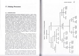
  • 1. 5 Joining Processes 5.I INTRODUCTION Unlike the manufacturing processes employed to produce a single compo- nent, the joining proccsses are used to assemble different members to yield the desired complex configuration. Such a con'plex geometry is either too difficult or impossible to obtain'by using only th'e manufacturing processes. The joining processes are so intimately related to the overall production system that tbese are also considered to form a class of manufacturing techniques. The joining of different elements can be either temporary or permanent in nature. Also, the mechanism of bonding may be either mechanical or atomic. All joining processes involving atomic bonding are of a permanent nature. In this chapter, we shall discuss the basic priniiples and mechanisms of all such processes. In doing so, we shall also consider the different physical, mechanical, and metallurgical factors which govern the quality of the joints. In mechanical bonding, the strength of the joint is less .than the combined strength of the origioal members. In atomic bonding, however, the situation is not necessarily so. A general basic classification of the joining processes is given in Table 5.1. In our discus- sion, we shall follow this classification. Another criterion used for a classification of the joining processes is based on the composition of the joint. According to this scheme, all join- ing processes can be grouped into three different categories, namely, (i) autogeneous, (ii) homogeneous, and (iii) heterogeneous. Irr the processes belonging to (i), no filler material is added during joining. All types o[ solid phase welding and resistance welding are examples of this category. In the homr.lgeneous joining processes, the filler material used to provide the joint is the same as the parent material. Arc, gas, and thermit welding belong to this category. In the processes of type (iii), a filler material different from the parent material is used. Soldering and brazing are two such joining processes. It may be noted that two materials w.hich are insoluble in each other, such as iron and silver, can be joined by a hetero- geneous process. This may be achieved by using a filler material (e.g., copper and tin) which is soluble in both the parent matcrials (i,e., iron and silver). As already shown in Chapter l, the bonding [orcc trctwccn two Inctallic atoms decrcases very sharply with thc irttcrittorttic tlistitncc. Whcrr thc rlistanc:c is tnrlrc lhatt ;t l'cw :tlotttit: sP;rcirrl',s (r.e., ;r li:w ttrtlislrottrs), thc irrtt:rirr:lirrg :rllr:rr.tivc lirrtr: rcrlut:cc to;tlttlosl r.cro. llttt lltc lirrcc trl(rcltcs ,40 ':FC EE 9E a, 60 c 2E b0E , Ex o'O :o Z> oo c g€ 6T , o o o ,OTNINC PR@ESSES coo OC o= .-o u-, oo c .F 6 ? .9 E a E O 3o cc d= .: -o 3' ! @ oC 6'O ui -q E- '=? d.9 r= tL o 6 a o (r') o Z o z o @ 9 F 6 a, 6 6 o E k o. @ .E cl '6 o .9a e lrJ dt^ o 7/, Eti 6 a! 35 6x. ,d= oZ -o fix o Z o z o co J 9 Z (-) tu o @oo LC dE -z o> Eoo 4€ TEU i5; 9oo -ac O'O o. !, x, C' .9 oa O.= 6E s? I o50 2T a) .' oo 'o .E E! U; ? o C }E sil &r 5q l-a : o c, U) .o d J t E (A c o d E L o o. E o tn o E 0. o a o a
  • 2. 288 MANUFAcTURTNG scrENCE sharply and attains a very large value when the distance is reduced. Thus, if it is possiSle to hring together two metalhc surfeces so that nothing but the grdin boundaries separate them, the two bodies will adhere with a very large force, resulting in what we call welding. However, in normal atmo- sphere, the metal surfaces are contaminated with layers of oxides and adsorbed gases. These layers are normally a few hundred angstroms thick. So, it is not possible to generate a stroog attractive force when two metal surfaces are brought in contact. But this difficulty can be eliminated when the contaminatiug layers are removed from the surfaces. Though this may appear as a problem for welding, it is rather fortunate to have these contaminating layers. For example, in the outer space, a major problem is not the welding but the unlwelding of surfaces. 5.2 PRINCIPLES OF SOLID PHASE WELDING The solid state welding processes may be carried out both at the room temperature and at an elevated temperature without, of course, melting any part of the joining surfaces. For a better understanding of the quality of a solid phase joint, it is worthwhile to recapitulate the strength and cohesion of metals. A deflect-free crystal fails by a cleavage along a crystallographic plane where the interatomic force is the weakest. As a result, two oew surflaces are produced, anC the surface energy y is defined as tbe work done in order to create these surfaces. The strength of a single crystal ,(o") is found to ber o":1!1',n, (s.l) whcre ,C is the modulus of elasticity of the material and d is the lattice spacing in the cleavage plane. Horvever, in a brittle soiid, tire tailure takes place by the extension of the cracks already present, and the buik strength is much reduced from that given by equation (5.1). In rhis case, the bulk strength (o6) is expressed as tr^, ob: (7)tt2, rvhere /(yd) is the length of the crack. In Chapter l, we have alrcady seen that the lailure of a polycrystalline ductile material is due to the movement of dislocations, resulting in plastic instabiiity, and this takes place at a stress much lower than that given by equation (5.1). The foregoing discussion indicates that the bulk strength of a material is much lower than the bonding forces o[ the constituent. atoms. So, a good welding does not require to achieve a strength cqual to that bctwccn the adjacent lattice planes. Moreover, it should bc rcnrernbcrcd that at thc room temperature, i.e., with negligiblc crcep, cvcr) u ptunc ol'l;rtticc rrrislit rl.oncaslcr, J.Ir., Mctalltrrt:y oI Wclrlirrl', Ilr.rrrrrli rr1,l liol,lcr rrrg, Allcrr .rr1l I Irrrvrrr. L()n(l()r!, ltrllo. (5.2) JOINING PROCESSES 289 is not weaker than the bulk material. This information is important because a cold weld junction is essentially a planc of lattice misfit. When two metal surfaces are brought inio contact, the real 3oiltact thkes place through a small area of asperities, This metallic bridging occurs even in the presence of adsorbed surface layers. The bridgeq so formed have the property of a true grain boundary, and hence are stronger than the bulk material. Some work hardening also takes place in the layers, just beneath the mating surfaces. If the yield streogth (or flow pressure) of the material is o, with the applied force as p., then the fraction of the total a:ea coming in contact, and thereby forming a weld, is simply (pJct). However, around the welding zones, there will be some areas which come in contact (without actual flow) where the stresses are still within the elastic range. The experimental results suggest that including this area, the total area of physical contact, with a moderate external pressure, can be tak-eu as 2p"lor. When the applied load is remot'ed, the two surfaces sepa- rate out only when the elastic forces trapped in the regions around the bridges are strong enough to break apart these metallic bridges. It is seen that the softer the material, the better the pirmanent adhereoce. In the solid phase welding processes, the four important factors are (i) surface deformation, (ii) surface films, (iii) recrystallization, and (iv) diffusion. The surface deformation that takes place during weldiog is difficult 1o measure. As such, in pressuie welding, the bulk deformation is used as an index of the surface deformation and is expressed as (for a sheet oforiginal and final thicknesses l; and fr, respective!y), t) tl dr - di x rcO% (for a circular specimen of original and final d; diameters d, and, d1, respectively). The strength of a weldcd junction increases with increasing bulk deforma- tion. Moreover, no weldment takes place below a certain critical deforma- tion. The amount of deformation necessary for obtaioing a specific strength decreases with increasing temperature. A stroDg weld may be made with orJy lol deforination if the working temperature is quite close to the melting point of the material. The ratio of the oxide hardness and the parent metal hardness also effectively governs the amount of necessary deformation. The greatcst hurdle in solid phase welding is posed by the surface oxide layers :rntl oil filnrs. The liquid films can be removed by heating in hot wclding, ;rrrtl l.ly n)cans of scratch brushing in cold welding. The oxide films can ulso lrt: rc<lrrccrt lo a ccrtain extent by scratch brushing. More- ovcr, llrcsc oxirlc l;rycr'. (lrcrnli ltirrrl ;urrl brittlc) fracturc when thc prcssurc is trpplicrl. A l;rlcl;rl urrvrnrrnl r, vcry useful (as in trltrasonic wcltlinl) sirrcc llris tetttls lo roll lul','11t,', llrc lr:tllrttctttcrl oxirlc lrrycr rltto;r rclrttivcly '+x rco%
  • 3. 29O MANUFAcTURINc sctENCE thick agglomerate. This results in a more metal-to-metal contact area. An excessive oxide contamination is always harmful, resulting in a poot- joint efficiency. A solid phase welding done at the room temperature does not allow recrystallization and grain growth at the interface. This reduces the ducti- lity of the joint to some extent. An increase in working temperature not only increases the ductility but also eliminates some other defects. The phenomenon of diffusion, though it has not been studied extensively, has an important bearing on the performance of a solid phase weld. The shape and the size of the voids at the interface are modified considerably depending on the amount of diffusion. 5.3 PRTNCIPLES OF FUSION (LIQUID STATE) WELDTNG In a fusion welding process, the matcrial around the joint is melted in both the parts to be joined. If necessary, a molten filler material is also added. Thus, a fusion welding process may be cither autogeoeous or homogeneous. Metallurgically, there are three distinct zones in a welded part, namely, (i) the fusion zone, (ii) the heat affected unmelted zone around the fusion zone, and (iii) the unaffected original part. The most important factors governing a fusion welding process are (i) the characteristics of the heat source, (ii) the nature of deposition of thc filler material in the fusion zone, klown. as lhe *'eld pool, (iii) thc heat flow characteristics in the joint, (iv) the gas metal or slag metal reactions io the fusion zone, and (v) the cooling of the fusion zone with the associated contraction, residual stresses. and metallurgical changes. 5.3.I HEAT SOURCE A heat source, suitable for welding, should release the heat in a sharply defined, isolated zone. IVlcreover, the heat should be produced at a high temperature and at a high rate. The most common sources of heat include (i) the electric arc (as in various arc rveldings), (ii) the chemical flame (as in gas rvelding), (iii) an exothermic chemical reac(ion 1as in thernlit weld- ing), and (iv) an electric resistance heating (as in electroslag and other resistance rvelding prbcesses). The general character.istics of these hcat sources are now discussed. Emistion and fonization of Electric Arc First of all, Iet us see how an electric arc iscreatcd and maintained betwccn two electrodes of opposite polarity. Figure 5.1 schcmatically shorvs an electric circuit used flor arc welding wherc thc work is thc positivc clcctrotlc (called thc anode) and thc clcctrodc rod is thc ncl1ltivc clcctrotlc (crrllcrl tlrc cathorlc). Initi;rlly, :t 1loorl cottlacl is lrtittlc lrclwct:tt lltr: clct:lt'orlt:;tntl tlrc JOINIn-G I'ROc[ss[s 29t rvork. l-hcrc.after, thc bridges starr breaking, elc'ctrode is withdrawn. As a thus increasing the currcnt result, lhe nretallic density per bridge. l-- lcct r /ork Fig. 5.1 Arc rvelding scheme. Fina'y, the current dcnsity rises to such. a.high varue that the bridges start ff"l;,*:;'i::n "onaiiion', tn' '1.",.*, "o.n. ort-oiioin ,n. surraces -#[il.x j:=;,::::::,,Jj:]i:?1,.":;::*,[fi ;:"T""il lhe anode. mrng out cf the calhode ,.. ulro ,ii."","d towards The rate at which thc erectrons are emittcd from a h.t surface is given by I : 662 exp (_p,,0), (5 3) ;lfi;t;; amp/cm2, d is the absolule rernperarure, c is a consranr, and p - gc;(kl) (s.4) uith e : charge of an.electron, I : .Boltzmann,s-constant, and / (when ;::::f;: ?,T:ll"' vorts) as *'' 't'"'^io,.ic .,'ork runctiort'." g,' in ract, rb. of / for sorne cornr energy necessary to 'boil'ouiun .i..irJn. The varues eq u a ri o n (5 3) rh;;' ":;1" :"f d a :::I; J:,I:f f ,if; H: :;;i *:;I :b"1i!:,T.'i::I.:";::t rr,*::,!,.,0. ; ;;;; becomes a paragraph). fl.r. iJr.*,I" ;::^:l,Ionrzarron (as explained in the next co,, i s i o n s i,.. ;- il q: : il r:i:H.J,,:t i lliilm ;: :i" t:"xh; t,o sers of elecrrons. The firsr ,.r, .ri,,la'by rhe ";,;;, ;.;ii.o p.l*"ry ;'','.'#' ;l i.r J i: ;;:: 1'.,, r oo,,,l'ur'rJ"or ou* erectrons, is prod uced as r rodes, r r,. p,i,,,,," y .:i.llJ :ll ::,,iii i,,i.iii ; JI:: ;; f * ;ll *ir,, _rlX "';'l':til:t;;lll :li:1ll ;j:, " 1,:i, l,:;;::l;i;,H:::,:. ::,:,r ,,,,*,-ii ,,," .,,..,, rlirl;rrr:t.), (.)rrlcr rcrr (. .r r,,r,,. ,,, rr,,,r:,,ru,t; ;;.lT lT;i:, 11,,filii:l:":;..,Jl:llJ ;tl ;t t;,lt' rtl rl..,'rtr, r ltcli lr rr tlt ,ttAr. .So, rt it lnlvrl( t1,r,.,,,.1. .r,
  • 4. 292 ilIANUFAC'TURING SCIENCE Table 5.2 Ionization potential and thermionic work function of some common metals Metal Ionization potential (v) 6 (ev) Aluminium Copper Iron Tungsten Sodium Potassium Nickel 6.0 7.9 4.t 4.4 4.4 7.83 8.1 5. l. 4.3 7.6r 4.5 2.3 2.2 5.0 before colliding with another particle (a neutral atom or auother electron), it has a kinetic energy eEd. This kinetic energy is nothing but heat and manifests itsell through increased temperature. The interparticle ccllisions, taking place in the gap between tbe electrodes, give rise to a process ce,lled tlternral ionization. Normally, these collisions are elastic and both the momentum and kinetic energy are conserved. However, occasionally a collision is such that an electron may be completely knocked out from a neutral atom, producing a free electron and a positively-charged ion. Such a collision is, of course, not elastic io nature. The ions thus produced are attracled towards the cathode, as already explained in the foregoing para- graph. The free electrons (earlier termed as the secondary electrons) help the arc to remain electrically conductive. A definite amount of energy is required to produce ionization in a given atom or molecule. This energy (in electron volts) is numerically equal to the ionization potential (in volts). The ionization potentials for different metal vapours are also shown in Table 5.2. Most of the ion-producing collisions in an arc are between hoi, neutral atoms and molecules. To maintain the conductivity of the arc, only a small fraction of the atoms need to be hot enough to ionize, whereas the rest of the arc should be hot enough to supply the fast atoms. For most bommon gases and vapours at the atmospheric pressure, the arc temperature is of the order of 6000"C. Arc struciure, characleristics, end porer Slructurally, wc oon distinguislr {ivc tlrt)'crcnt zones in nn elcctric Irc. 'l hcsc nrc nr follows, ,.'.t,,, JOINING PROCESSES 293 (i) Cathode spot This is a relatively very small area on the cathode surface, emitting the electrons. (ir) Cathode space It is a gaseous region adjacent to the cathode and has a thickness of the order of l0-3 cm. This region has the positive space charge, so a voltage drop is necessary as the electrons are tb be pulled across this region. (iir) Arc column This is the visible portion of the arc consisting of plasma (hot ionized gas) where the voltage drop is not sharp. (iv) Anode space This, again, is a gaseous region (thickness =10-3 cm) and is adjaccnt to the anode surface where a sharp drop in tbe voltage '-akes place. This is because the electrons have to penetrate the anode surface after overcoming the repulsion of the thermionically-emitted electrons from the anode surface. (v) Arrcle spot This is the area on the anode surface where the elec- trons are absorbed. This area is larger than the cathode spot. The potential drop across an arc is schematically shown in Fig. 5.2. The Anode Cathode Potential Fig. 5.2 Potential across arc space. voltage drop shown in tbis figure.is for given spacing, current, and electrode materials. A change in the materials alters all the values. However, a change in the spacing and the current essentially changes only the drop in the arc column. It has been experimentally found that, for given spacing (and, of course, etectrode materials), the voltage reduces up to a current value of 50 amp (against the ohmic law of constant resistance) and increases thereafter, as shown in Fig. 5.3. I'his can be explained as follows. Up to 50 amp of currcnt, thc slrapc ol'tltc arc is almost cylindrical and the surface to volume ratio ol u cylinrtcr <ler:rctrscs with incrcasing radius. Thus, a thick, high clrrrcnt arc I,rst's lesr ltc:tl tttttl csscnliitlly brrrns hotlcr. 'l ltis rcsults in a !tiglrcr c6lrlut:livity (lrrrl r ortrer;ucrrlly lowcr rcsislttttt:c) its t:ontJrltrcrl rvith rl lhin, lprv t'rrrrcll 111s'. tlowrvcr, hcvortrl 50 tttttp ol t'ttttcttl, lltc itrc lrrrlpcs (,) c- ,J ! Arc colunrn Cathode soace
  • 5. 29-t MA NUI.ACTURING SCIENCE Current (amp) Fig. 5.3 Current-voltage characteristic of arc. out and thi current path becomes more than the atc gap which again in- creases the resistance of the arc. Due to these two opposite effects, i.e., higher temperature and longer current path, the voltage drop remaies cons- tant over a wide range of the current values. As a first approximation, we can assume the conductivity of the arc column to be independent of the arc length /. The electrode drops are also independent of the arc length. l{ence, we can write the voltage drop across the entire arc as v : A -f Bt. (5.5) rvhere I is the electrode drop aod Bl represents the column drop. The voltage-current relationship of an arc (Fig. 5.3) determines the required characteristics ot'the power source. In Fig. 5..1, rve consider trvo different characteristics of the po,er source. The curve l8 represents a flat characteristic, rvhereas the curve CD represents a sharply drooping one. In this figure, two typical arc characteristics for two different arc lengths (say, / and / ,- /l) are also indicated (see the dashed lines). The intersec- tions of the characteristic o[ the source and that of the arc determine the operating points. It can be easily seen that the stable operating points are given by the intersections on the right-hand side (shown by the solid circles), and not by those on the left-hand side (shown by the solid squares), of the figure. This can be verified by considering a change, say, an increase, in the arc current. At the points shown by the solid circles, such an increase causes an increase in the voltage which, in turn, decreases the generator (sourcc) current. Thus, any disturbance is automatically opposcd, and the operating points return to their original values. At the points shorvn bythe solid squares, just the opposite phcnomenon takes place, i.c., any distur- bancc nrovcs thc opcraling points conlinuously away frorn tlrcir oriliinal l<lclttions. 'l'hc changcs in thc :rrc currcnt lilr tltc l'() l)()u,(.r sorrrccs lirr ;r liivcrr t'lr;rn1lc irr lhc :rrc lcrrlitlr (lrorrr / lo I | /1ll rrrc :rlso rntlicatc<l irr liit' .l ln manual arc rvelding, an inadvertent change in the arc' length is inevitable. However, this should not cause a large changc in the u'elding current. This obviourr; ;,"k., the sharpty drooping characteristicdesirable formanualarcrvelding.withaflatcharacteristic,forabigcirangeinthe arc length, ttrere mai not be an-y .point of in{'ersection betq'een thc arc and the source ctraracteristics and the arc nray blow out''For'an eflicient striking ol tlie arc, it is necessarv that the.:"' til"llt ':"]:1t" of the source be high above the operatine voltage' Morcover' it is necessary to have a quick response o[ thc source (low tinre constant) since the welding process itself rs unsteady' The power to'-t:: shculd be such that it is not damaged by short crrcuiring flor an appreciable length o[ time' In a semiautomatic arc welding process' the arc is maintained between the workpiece and " t;;; ;;i;h i a'iutn lorrvard at a constant speed as it melts arvay from the tip' An iocrease .in the arc lcngth increases the voltage [equation t:':tt lla, us a result' the current falls' The me lting rate being dependent on the current' an increase in the arc length causes a decrease in the mefting rate' Il the reduction in the current due to an increase io the arc r""gitr'ir-rignifi"uo,, the melting rate decreases consider- ably so that the "J'i;;;n;turn-s to.its original value' Hence' in this case, for a stabl. ;;t;;i;;', a {lat characteristic of the power source (Frg. 5.4) is dcsirable. ..-.-.r, ..,...{ rt.^re ic :rr 'l'ltt: Po*'cr o{':tn arc vrtrtcs u'i.tlt its lcngtlr 1:':tt tl"lt::..an optrnlunr lctt1,'tltltrlu,llit.lltlrcltl(:I)(),(.listtlltriltlrt.tl.,llris.i;llirtttttli:rrt:lcnStlt (/.,,,) , :trt lrc tlr'lt'l tttiltctl :lr ll()ll"rvs I r)l :t l't'('ll lt'rrlllll' :':l" /l ' lrtst tltt' lttt' r,,,ll.rll,'(l') ll rlt'lcltttlttr'rl lr()llt ('rlll'lllott ('r''r) llrcrr' ll()tll lll('('|()lllt(' ,1,,,r,,, t.ll'.ll( (l "' '; ''; lltt' 'tt t ""t'ttl (/) r" 'l''l"rttltttr''l l'rr lltr" r'tlttr r'l o al) = o I I t t I I I $ r-- tr ra it 1 a I o t:r, a = o -Sharpli' drooPing Flat o-' JOINING PROCESSES 295 t+ lt a a Ior cltrtt,gc in rrrc lcngth fronrilol Jl t---- Fis. 5.4 Changc in Curtcnt I arc current for a change in arc length' I t-- -st'? K.d
  • 6. 296 IIANUFACTURING SCIENCE the arc voltage. The product of these two, i.e., vI, gives the power (P1) for the given arc length ir. This procedure can be repeated for various values ofthe arc length and a plot of the arc power (P) versus the arc length (/) can be obtained (Fig. 5.5). Now, the optimum arc length lepl csD be easily determined from this figure. Since the electrode drop is utilized ll Arc length / Fig. 5.5 Arc power versus arc length' with a higher efficiency than the column drop, the actual optimum length is a bit shorter than the optimum obtained from Fig' 5'5' EXAMPLE 5.1 The voltage'.length characteristic of a direct current (dc) arc is given bY V : (20 * 40/) voits, where / is the length of the arc in cm. The po*'er source characteristic is approximated by a straight line with an open circuit voltage : 80 V and a short circuit currcnt : 1000 amp. Determine the optimum arc length and thc corresponding arc Power. SOLUTION The power source characteristic can be written analytically as 80 7: (S0 - ffiI) volts. The arc characteristic is given as V : (20 f 40/) volts. Equating (a) and (b), we obtain 8q-fSI:20+4ot or I '- (60 - 4o/)lmo "'nP' ! o o. 3 t, loo, (a) (b), JoINING PRocEssEs 297 Hcnce, the power P is obtained from (b) and (c) as P : VI: (20 + 40/X60 - 400# volt-amP' For maximum Power, t--n dl or 40(60 - 40/) - 40(20 + 40I) : 0 or 1600 : 3200/ or /: 0.5 cm. So, the optimum arc length lop, : 0'5 cm when the maximum power of the arc is P-." : (20 + 40.+)(60 - 40't)1330 'ort-"*n : 20 kvA. In our discussion so far, we have talked of a dc arc' Every half cycle of a50-Hzalternatingcurrent(ac)takes0.0lsec,whereasanarctakesonly about 0.001 sec to reach the equilibrium state. Due to this quick response' bothFig.5.3andequation(5.5)areequallyapplicabteforeveryhalfcycle of an aJ arc as weli. It should be remembered, however' that an ac arc must reignite itself alter every crossiog of the zero current instant. Reigni- tion reqiires a voltage highir than the normal arc voltage. The process of reignitionofanarcisfacilitatedbythepresenceofionshavingalow iorfzation potential. So, the electrodes for an ac arc welding are coated ,"iit po,urrium silicate binders, whereas those used for a dc arc welding are nlrmally coated with sodium silicate. From Table 5.2, it is readily seenthatpotassiumhasalowerionizationpotentialaScomparedwith sodium. Chemical Heat Source Acetylene(CzHz)isthenostcommoDchemicalheatsourceandisusedin a chemicat gas flame. In the presence of excess oxygen' it burns according to the reaction CzHz * !O2 '= 2COz l- HrO + beat (/H) (5'6) Theamountofherrtlihcrrtted(ltI)isl.275xl06kJikg-moleoIacetylene. If nryg.n is prcmixerl rvilh ncc(ylene (onc-to'one :nole ratio)' then the conrhttstion rettcliolt ts (c) Clzllr I Or , ?('(l I llr I lreul (//Ir) (s.7)
  • 7. 298 MANUFAcTURINc sclENCE with /I{ : 0.448 x 10⁶ kJ. The carbon monoxide and t}re hydroge produced later burn, Producing AH, - /H2:0.827 x ltr kJ/kg-mole of acetytene. However, this heat, since it is generated over a large volu and at a low temperature, does not add much to the welding proccss. Once thc amount o[ heat tiberated (AH) is known, we can rough estimate the maximum flame temperature with the assumption of an adia batic flame. This means that the entite AH Ieaves the flame only throu the heating of the reaction products. Care must be taken to subtract t tatent heat from AH if any of the reaction products undergoes a change phase. The entire reaction is assumed to be completed at the room tempel iure (say, 0e). Then, the flame temperature (01) can be computcd from t equation ZEI : lH - (latent heat) : z [o^' ,c;01 ao. . n Jop. In' equation (5.8), the summation is taken over ,, moles of each of t reaction products and Cr(d) is the molar specific heat capacity of products which vary with the tcmperaturc. For reaction (5'7), the (5.8 temperature obtained is around 3560"C, whereas the measured temperat of the flanre varics frcm l280'C (minimum at tlre tip) to 3250'C (maxim at the core). Another chemical source of heat, commonly used for rvelding, is t reaction 8Al + 3Fe304 :2Fe * 4Alz0r + AII where lH :0.242 x 10⁶ kJ/kg of atomic weight of the contained The adiabatic temperature is calculated to bc of the order cf Reaction (5.9) is utilized in rvhat is known as thermit welding' Contect Resistrnce Heat Source The electrical resistance heating, as alreaCy stated, too is a heat source This may be done either by utilizing the contact resistance of the in (5.e oxygen 3000'c (as in various resistance u,elding processes) or by utilizing the resistance a molten flux and slag (as in electroslag welding). wc havc already noted in Section 5.2 that when two metallic surfr are brought into contact, only a small fraction of the apparent area rs i actual metal-tc-metal contact. When a current is sent through such ioteiface, all of it is carried by these tiny metallic bridges. Thc oxide I in contact cdrry no current. As a result, the current flow is constr-icted, intlicated in Fig. 5.6. Due to this constriction, the resistance to the flow current increases, and this rncrtment is termcd as contact resistance. estimate of the ordcr of magnitude of this resistance can bc obtaincd idealizing theconstricled current flow (as shown in I;,g.5.7) witI the ltrllow ing assumptions;
  • 8. 298 MANUFACTURING ScIENCE witb AH2:0.448 x 10⁶ kJ. The carbon monoxide and ttre hydrogen produced later burn, producing AH, - AH2: 0.827 x lff kJ/kg-mole of acetytene. However, this heat, since it is generated over a large volume and at a low temperature, does not add much to the welding proccss. Once thc amount of heat liberated (AH) is known, we can roughly estimate thc maximum flame temperature wit.h the assumption of an adia- batic flame. This means that the entire AH leaves the flame only through the heating of thc reaction products. Care must be taken to subtract the latent heat from AH if auy of the reaction products undergoes a change of phase. The entire reaction is assumed to be completed at the room tempera- ture (say, 0p). Then, the flame temperature (d1) can be computcd from the equation (5.8) In equation (5.8), the summation is taken over ,, moles of each of the zr reaction products and Cr(d) is the molar specilic heat capacity of thcse products which vary rvith the tcmperaturc. For reaction (5.7), the ffame temperature obtained is around 3560'C, whereas the measured tenrperature of the flame varics frcm l280"C (minimum at the tip) to 3250'C (maximum at thc core). Ano'ther chemical source of heat, commonly used for rvelding, is the reaction 8Al + 3Fe3Oa :2Fe | 4Al2O3 + AII (s.e) wherc lH:0.242 r 100 kJ/kg of atomic weight of the contained oxygen. The adiabatic temperature is calculated to be of the order cf 3000'C. Reaction (5.9) is utilized in what is known as tllermit r+'elding. Contrct Resistance Heat Source The electrical resistance heating, as alreaCy stated, too is a heat source. This may be done either by utilizing the contact resistance of the interfaces (as in various resistance n'elding processes) or by utilizing the resistance of a nrolten flux and slag (as in electroslag welding). We have already noted in Section 5.2 that when two metallic surfaces arc brought into contact, only a small fraction of the apparent area is in actual metal-tc-metal contact. When a current is sent through such an inteiface, all of it is carried by these tiny metallic bridges. The oxide Iayers in contact carry no current. As a result, thc current flow is conslfictcd, as indicated in Fig. 5.6. Due to this constriction, the resistance to thc llow of current increases, and this rncrement is termed as contact rcsistancc. An estimate of the ordcr of magnituric of this rcsirl:rrrcc can bc obt:1islg1l [y, idcalizinli tlrcconstrictc<l t:ttrrtrtl flow (rrs slrowrt rrr I ,11. 5'l) rvrllr tlrc lirllo* illl{ ;rlrtrrl)l ron. ZH: lH - (latent heat): l[lr'*,,c,O1 ao. n -fE--ra!4 tt' ....t-|= - In terfacc #. - -- hr-- 'l'[etallic bridric .; Fig. 5.6 Formation of metaltic bridge. JOINTNG PROCI]SSES Fig. 5.7 Idealization of constrict- ed current flow. (s.12) (i) All bridges are of uniform size and sphericar shape rvith radius 11. (ii) All bridges are uniformll, spaced at a distance 2r2 apart. (iii) Thc constriction effect due to."th br)dge is restricred rvithin a con_ centric sphere of radius rr. (iv) Each bridge is o[ zero resisrance. No*,, if there are , bridges pcr unit area, then rhc contact res;stance per unit area can be carcularec fiom the resistance ofeach sphericar constriction and considering , such paths in parailel. Each sphericar constriction consists of trvo identical hemispheres in series. The resistance of each hemispherical constriction is given by whcrc p is the resist,ivitl' or- rhc nrateriar, (r, - r) is ttre Iength of the current path, and s is the geornelr.ic mean area of the two bemispieres or raaii 12 and 11, respectively. Thus, 5:vt12,$@{:2trr2r1. Substituting this value of S in equarion (j. I0), we obtain R:P(tl-rr)==L Irf2t1 2tr1 R:p(r2-rr)iS, (-5.10) (s.r l) since 12 > rr. Hence, the totar constriction resistance per unit area is given by p-:? L: p. - tt 2nrt nnrl ln thc abscrrcc .,l rlr. rrrrt rr:rt c, rhc rcsistancc of llrc sanrc path is ncgrigibrt.. 'l'lrus, thc c()nrirr:I r('sr:,r;ur(c ;rcr rrrrir :lrc:r clu) llc t:rkclr;rs rlrrrr 1irvt., lry <'t1rr:rliorr (" l?) I.xPcrrrrrr.rrl,, ,.lrou, llr;rl llrr.;rsstrrrrPltorrs lt..rrlrnli lr) (.(llt;tll()n 1 l,)) rlo nol (;ut,,(. iln (.urrt ltrol1. lt111s1 ti),,. So, lltr.rurrl;rt.l t(,r,tfrliul((. Bridge o[.radius 11 Zonr'of irillue,rce
  • 9. 3OO MANUFACTURING SCIENCE unit area can, finally, be taken as ' R" : O.8iplbrr). (s. I 3) The rate of heat generated by this contact resistance with an applied volt- age Y is Y2lR" per unit area. However, after a very short time (=0.001 sec), the contact resistance drops to about G)-tn of its original value. This is mainly due to the softening of the material as the temperature increases. As the material softens, the value of the quantity (zr1) used in equation (5.13) increases. This effect is more predominant than the increase of the bulk resistivity (p) with the temperature EXAMPLE 5.2 In a resistance wetding process, the applied voltage is 5 V. Determine the rate of heat generated per unit area with 25 bridges/cm2, each bridge having a radius of 0.1 mm. The resistivity of the material is given to be 2.x lO-s ohm-cm. SOLUTION '.fhe contact resistance per unit area (R.) from equation (5.13), with n :251cm2, is ^. - o'-8I x 20 { l-o-5 : i.oooz ohm-cmr. rrc - 25xzrx0.0l Hence, the rate of heat generated per unit area is given as .n_5x5_-.a-. R" O.ffi w/cm2 : 1.136 x lOs W,,cm2. 5.3.2 MODES OF METAL TRANSFER IN ARC WELDING The depth of penetration, the stability of the weld pool, and the amouot of spatter loss depend, to a Iarge extent, on the mode of metal traEsfer trom the consumable electrodes. various forces cause the transfer of metal into the weld pool. The mode o[ transfer depends on the intersection of these [orces and governs the ability of welding in various positions. The major forces which take part in rhis process are those due to (i) gravity, (ii) surface tension, (iii) electromagnetic interaction, and (iv) bydrodynamic action of plasma. The force of gravity may be a retaining or a detaching force, depending on whether the electrode is pointing upward or downrvard. But'the surface tension always teDds to retain ttre liquid drop at the tip of the electrode. This force depends on the radius of the electrode, the capillarity constant. and the density of the Iiquid metal. The electromcgnetic force,'known as the Lorentz force, is set up due to the interaction of thc electric currcr)t u'ith its own magnetic ficld. This force acts in the direction of thc currcnt rvhen the cross-scction of thc con<tuctor is increasing in thc rlircc;tion ol'tIt: (:urrcnt. Sintilarly. llrc firrce lrcts in lhc rlrrcr:liolr oPPosilc lo lllrl ol'llrt_. ('rrrrcnl il llrc cross-scclt()n ol the corrrtrrcl(,r l rcrtrrcitrg rlr ltrc dirccliorr of 't' JorNrNG PRocESSE.S 301 the current. Figure 5.8 cxplains horv this force accelerates the process of separation of a droplet which has started to separate out. The hydrostatic pressure is created due to the magoetic force. At a high current density, this pressure elongates the liquid drop and also adds to its stiffness. As a result, the liquici drop is projected along the line of the electrode, indcpen- dent of gravity. EIect rodc Lorentz forces Wcrrk Fig. 5.8 Separation of droplet. i The piasma of the arc also causes the drop to be projected to*,ards the rvorkpicce, whereas a high evaporation ratc from the surface of thc drop tends to rnove it in the opposite direction. All these forces interact in a complicated manner and give rise to two broad classes of metal transler, namely free flight tiansfer and short circuit transfer. In the former, the liquid drop travels freely in the arc space, i.e., gets completely detached from the electrode before contacting the work- piece. The free flight transfer may be (scc Fig. 5.9) (i) gravitational, I;ig. 5.9 Types of metal transfers. (ii) projcctctl, irrrrl (rir) rcpcllt:tl. Whcn the transfer is gravitational, thc Jlrc<lolltilt:tltt lirtr't't', llt;rl ol 1'rirvity and l!rc mollcn d161, [alls:rlrrr.sl vcrlit::rlly frottt lltt' t'lrr ltorlr tttlo tltc wclrl pool. If llrc clct:trolrr:rlirrclic firrt:c, llrc plrs jcl, rrrrtl llr, lti'rltrrrlrtlic J)rcsstrrc ltic l)rc(l()ntut;rnl, lltcn llrc rltort ir girett att tltilrnl aeiclCralton lowtrrrls llrc rvclrl nool. nrrrl tlrrrr Cu rlc'nl <lirection Projcctcd
  • 10. NTA NUFAC'[URING SCIENCE projected into ii independent of gravity. If the resulting force directs the drop away from the weld pooi, then the repelled transfer occurs. This situation is encountered when COz is used as the shielding gas, particularly at low and moderate currents. Obviously, the gravitational transfer is not very reliable, and the repelled transfer is undesirable since it causes too much of a spatter loss. The projected transfer is seen in oxide coated carbon steel electrodes where a strong gas jet is set up. In the short circuit transfer, the liquid drop at the tip of the electrode gets in contact rvith the weld pool before being detached from the electrode. Thus, the arc is momentarily short circuited. However, due to the surface tension anii the electromagnetic force, lhe drop is pulled into the weld pool and the contact with the electrocle is broken. This re-establishes the arc. Figure 5.10 schematically shows a shcrt circuit transfer. Here, the spatter ig. 5.10 Short circuiting transfer. Ioss is minimum and can be achievcd by conirolling the gap and the other welding variables. This type of transfer, beirrg independent of gravity, is suitable for overhead welding purposes. 5.3.3 HEAT FLOW CHARACTERISTICS A study of heat flow characteristics can provide an estimate of the mini- mum heat input rate required to form a weld of a given width. Moreover, a recognition of the major variables controlling the thermal cycle (i.e., the heating and the cooling rate of the heat affected zone) is essential lor a successful fusion rvelding. In the fusion welding processes, the heat source is moving, except in spot welding where the sourceis stationary. Once the steady state is reached, even with a moving heat source, the temperature distribu- tion relative to the source becomes stationary. The most convenient way of analyzing such a problem with a moving source is to assume the source as srationary and the workpiece to move with the same velocity in the oppo- site direction. This speed is called the welding speed. Two different types ofheat sources can be considered. In most cases, the heat is libcraicd in a small zone which is idealized as a point source, and thc hcat flow frorn thc source is three-dirnensional. In a fe rv cascs, e.g., in butt wcltlinll of'rclir- tively thin platcs, thc hcat is libcr;rtctl ulorrll:r lirrc:rn<l thc lrc;rt s()ur(:c i itlcaliz.ctl rts:r lirrc s()llrcc. lrt sttt;h $rlttllr()ns, llrc ltc:rt llow is lwo rlrrrrcrr. siottitl, 'l ltest: lwo lYpes ol'lteul soult'e'l llrc cxl)l.lttlerl trr l't,{. I I l. lror rtlr # ; i I I i JOINING PROCESSES 303 (a) Point source. tenrperature : [(x. 1;.: ( b) Linc source; !emperaturc : -f(x, y) Fig.5.ll Point and line heat sources. elaboratc analysis of the temperature distribution in the *orkpiece under various situations, see the Iiterature. The available results include those of infinite, semi-in{rnite, and finite medium, each with point and line sources. Of these results, the most useful is the one n'hich gives the minimum heat input rate necessary for maintaining a given wiCth of the weld. For a three- dimensional heat source, this is given asl t (5. l1) e: Fswkl^G +fr), where Q: rate of heat input (W), rr, : width of the weld (m), k : thermal conductivity of the work material (W/m-"C), d- : mglting point of the work material above the initial temperature ("C), u : speed of welding (m/sec), cr : thermal diffusivity of the work material (m2/sec) k - p, P - uvuor r.)r ' L - rPuvrrrw r lirr lr two-dimcnsional hcat sourcc, thc corresponding equation is git'en by () t<t0,,,/r1| I lox'), (5.1 5) tl arx artet. J.1 .. I,lrl{llutgy ol Wrlrlrrrg, llturrrrg ttrrtl Solrlctrrrl:, Allcrr ttttrl I Irtwirt, l.r)il(l([r. l')lto Weldirrg
  • 11. ilri 304 NTANUFACTURTNG scrENCE where /r : plate thickness. It is clearly seen from equations (5. I 4) and (5. I 5) that the most important parameter is uu/a. , It should be noted that the theoretical results fail to accommodate many practical considerations, e.9., inhomogeneous conducting medium (liquid within the weld po<il and solid outside), and absorption and rejection of the latent heat at the forward and the rear edges, respectively, of the weld pool. However, equations (5.14) and (5.15) are still useful for providing a good estimate. In arc welding with short circuit metal transfer, the heat input rate is casily seen to be Q: CYI, (5.16) where Y: arc voltage (V). I : arc current (A), : C : fraction of total time during which the arc is on. If the heat input rate given l-ry equation (5.16) falls short of that given by equation (5,14) or equation (5.15) (as the case may be), a lack of side fusion occurs. EXAMPLE 5.3 In a butt welding process using arc welding, the arc power is found to be 2.5 kVA. The process is used to weld two steel plates, each of 3 mm thickness, as shown in Fig. 5.12. Determine the maximum possible ABI I-.AX* -1,,, T Fig. 5.12 Work for butt welding process. welding speed. lt is assumed that the metai transfer is of shorr circuit type aud the arc is on for 857o of the total time. Given dsiccr : 1.2 x l0-5 m2/sec, ksrccl : 43.6 WimsC. The melting point of steel: 1530"C and the ambient tsmperature:30oC. SOLUTION The rate of heat input is given as Q: CVI [using equation (5.16)] r : 0.85 x 2.5 x 103 W : 2.12 x [0] W. (a) The minimum width of weld to be rnaintairlctl is givcrr by w ^ AB .,. 2r/1 nrm :' 2{7 x lO '' nr. JotNrNc pRocEss[s 305 Also, 0-: 1530"C - 30'C.= l500oc, h: Jy l0-r mnr. As in the butt welding of thin plates, so too here the source can be approxi- mated as a line source. Thus, using equation (5.15), Q:8x41.6x 1500x 3 x 10-3(0.2+H). (b) Equating Qftom equations (a) and (b), we obtain 2.12 xl0r : 8 x 43.6 x I5 x :10.2 1 fl; or o.l + 911': l.l-i or lY : r.os. ' 4t 4u. Since r('-;n : 2{3 X l0-l m, we have umax: 1'#rTr|21x l0-5 misec:0'0146 m/sec' r In fusion welding, the otirer important heat flow variables are the cooling rare and the thermal cycle. A mathematical analysis leads to 'the follorving conclusions which are in accordancc with the practical experience. The cooling rate increases with increasing u'eld speed, and for a given weld speed, the cooling rate increases with decreasing size of the weld pool. For cxample, in eleciroslag weiding, since the weld pool is large and the rvelding speed is very slow, the cooling rate is seen to be very low. On the other hand, in automatic tungsteo-ine rt gas weldiog, the process is operated at a very high speed with a small weld pool, and this results in a very fast rate of cooling. The thermal cyclc at any point in the rnedium is mainly governed by its distance from the heat source. Obviously, with increasing distance from the source, the maximum temperature is lower and the temperature lags further behind the source. Figure 5.I3 sho.ws the variation of temperature with time at different distances from the source. 5.3.4 GAS METAL REACTION The absorption of gas in the weld pool from the arc or the flame plays an important rolc in nrosl fusion welding processes. This is due to the possi- bility of a rcaction l)clwecn tlre gas and thc liquid metal in the weld pool. -I'hechancesof suclt n rc;r(:lr(,n nre cnhanced by the high temperature of the 11ns nnd the rttclll. 't'lrerc cln l)c tw(, rlillcrrtrl lygre r of reilcliorls. ln rtnc lype, thc Sils ttlily iurl get {irrolvcd in tlrc hqultl nrclrl. ln lhc rcconrl typc, on tlrc olltcr ltttttrl,
  • 12. f'IANUFACTURING SCI EiiCE Tirne Fig. 5.13 Variation of temperature with time at different distances firom source. the gas and liquid metal may react chemically to form a stable compound- In such a case, the situation may be considerably different, dcpending on the degree of solubility of the reaction product in the weld pool, As long as the reaction product is soluble, it does not prevent the for- mation of a rveld pool. Horvever, it may result in an embrittlement of thc welded joint. An insoluble reaction product produces either surface scales or slags, and thus physically interferes rvith the fcrmation of the weld pool. In thii case, either the excess gas to the weld pool is prevenled or a flux is used to dissolve and disperse the reaction product' When the gas gcts dissolved in the liquid weld pool, there is obviously no hindrance to*,ards thc formation ol the weld pool. Ho$'cvcr, aS thc solubility decreases on coolin-e, degassification starts and, with suitablc nuclei, bubbles may form. If these bubbles are trapped, then the quality of the weld is very poor. Even otherwise, this degassification makes the joint porous. This defect is very common in a metal $'hose oxides are easily ieducible by hydrogen, and can bi: avoided by the addition of :t suitablc deoxidant in the filler metal. Another important gas metal reaction is the diffusion of the gas into the parent metal from the weld pool. When the temperature of the thermal cycle is high, this diffusion process may be quite fast. The diffusjon of hydrogen into the heat affected zone may, again, cause an embrittlement of the. welded joint. 5,3.5 COOLING OF FUSION WELD The three important cffects intimatelv connectcd witlr thc cooling ol'lr fusion wcld arc (i) contraction, (ii) rcsidual strcss, and (iii) nlcr;rllurgicsl phasc tr;rnsfrrrmntion. All thcsc c,I6-cts signilicuntly control thc qu11lrty r.rf rr wcld. {J L o o- .o F Distaiice ll'orn heat sourcc .lOINING PROCESSES 307 (i) Contraction During the freezing of the weld pool, a decrease it] the volume takes place. Moreover, the direction of freezing, and thus the effect of contraction, depends on the type of joint, as explained in Fig. 5.14. Partly frozen Conrplctcl_v frozen (a) Outside cor:le r (eroclrc) Partly frozen CcmPlct.-lY frc'zcn (b) Inside corner (trce) Fig. 5.14 Solidificatiorl pattcrns ltrr groove rvelds' Figure 5.14a shorvs the solidification of a groove lveld.. Here, the solidifica- tion front moves simultaneously from the bottom up$'ards and from the sides in$,ards. Further, the molten top portion always makcs up for the contraction in the inner layers and piping occurs only in the surlace Iayers. Figure 5.14b shows the solidification in a corner joint where more cold metal is near the surface of the rveld pool. Thus, the top of the weld pool freezes faster and a Iong piping thioughout the joint may occur' (ii) Residual stress During the fusion'welding of plates, as the weld pool contracts on cooling, this contraction is resisted by the rest of the plates (which have not melted). As such, a tensile stress is generated in the wetd, and this is balanced by the compressive stress in the parent metal. Figure 5.15 shows a typical distribution of these stresses in a plate weld. This residual stress may result in the cracking of a brittle material and is not important as far as a ductile material is concerned' (iii) Metatlurgical changes Thcse changes are due to the heating and sutrsequent cooling of thc wcld and thc hcat affcctcd zones of the parent nrntcriflls. such clranllcs sig,nilicilrrtly i.llcct lhc tlurrlity <lf tltc wcltl. Thc widc vuricly pl'clrnnlics lltitt ttttry tlkc pltrcc <lepcnd ott vitriott.s faclprs, c.1',., (n) llro lllturc ol' lltc trlutcrinl, t,c., rittglc-plture, lwo'pltttse' Molten metal w
  • 13. 308 MANUFACTURING SCIENCE JOINING PROCESSES Tensile strcss in rvcld Original workpiece edge Melt boundary oarse I Recrvstallized I'*-, jrains Conrpresstve slress in parent mctal Original cold worked metal Liquid Heat affected zone Fig. 5.16 Characteristics of rvelded joint in putc lrretal. Prccipitation Fig. 5.17 Characteristics of rvelded joint in precipitation hardened alloy. metallurgy oI such alloys, and must be clearly understood to yield a satis- faclory ftrsion wcld. AIso, a decision on the postwelding heat treatment to bc givcn rrrrrsl lrc l;rkt'n lo rjslore the desirable characteristics of the joint. 5..r I'tatN('lrt,r's ()li s()l,ll)/l,lQt)ID s'I'A'I)i JOINING 'l lrrcc rlrllclr.trl pr,rr r .,ir',., n'ulrr'ly. lrl:tzirt1i, s,rlrlctiltl'.,;trt<l ;ttlltc',ivc lrotttltrrli o o t< ! 60 Fig. 5'15 Stress distribution rn Plate weld. (b) the nature of the prior heat treatment' if any' and (c) the nature of the prior cold working' We now consider typical examples of these changes' Let us consicler the fusion *.lding of two pieces of a single-phase material' which have been cold worked to yield a desired grain orientation' These coldworkedgrainsresultinahighstrengthandlowductility.However, on fusion weiding, a random grain growth again takes place .within tbe melt boundury, *hi"h, in turn, results in a low strength' Within the heat ;.;;;;;", tu" gr"in, become coarse due to heat input (annealing)' and a pu.iiuf r.".Vrtuttirution also occurs' In either case' the streogth falls much below that of the parent material' With increasing distance from the melt ioroOury, the grains become finer until the heat unaffected zone with "f.rt",.J grainJi, reached' AII these changes are shown in Fig' 5'16' Letusnowconsrderatwo-phasematerialwhichderivesitsstrength mostly from precipitation hardening' In this case' the streogth within thc melt boundary is again too low' But' in the immediately adjacent heat affected zone, the thermal cycle results in heating and quenching followed ty-f,r.itt., aging. This aging process recovers some of the strength' The material beyond tnis zonJis only overaged due to the heat of ryrlding and ;;;;;; u."a.r with the loss of strength- Hence , the strength and ductilitv nhri.tioo near the joint are as shown in Fig' 5'17' Thetwoexampleswehaveconsi<lcretlclcarlyttetntlltslratclltlrtvarirlus typ"* .rr mcrallur!ical changes arc possitrk: rtrtI irr1,i wclrlrrrl" p:rrtit'rrlltrly firr .',rr,pt", irll()ys' 'I'hcsc cltltlr["es lltr ;iovrltteri lry llre rl()tl c(lllllll)Iltrllr Overaged Original precipitation hardened nretai Heat affected zorte Strength
  • 14. 310 MANUFACTURINcScIENCE are grouped under solid/liquid state welding. The physical phenomena a-sso- ciated with each of tbese processes are essentially the same, and differ imainly in the metallurgical aspects. In these processes, the bulk material is not melted. AIso, a molten filler material is used to provide the joint. 5.4.I SOLDERINC AND BRAZINC The soldering and brazing processes are carried out by allowing a molten filler material to flow in the gap between the parent bodies. Obviously, the filler material has lo have a melting point much lower than that of the parent bodies. When the filler material is a copper alloy (e.g., copper-zinc and copper-silver), the process is called brazing. A similar process with a lead-tin alloy as the filler material is called soldering. The most commoD heat source for these processes is electrical resistance heating. The copper-silver phase diagram is shown in Fig.5.l8. Here, we see that by varying the composition of the alloy the flow temperature can be controlled in the ratge 750-980"C. Similarly, the lead-tin phase diagram (Fig. 5.19) indicates a flow temperature in the range t60-300"C. d+L "*F ,OININC PROCESSES 3I I wherc y57y is the surface free energy of the solid/vapour interface, /s/r- is the su'face free energy of the sorid/riquid interface, and ytru is the surfacc free energy of the liquid in equilibrium with its vapour. -The surface free eoergy' if expressed in Jlmz, is numerically equal to rhe surface tension force expressed as N/m. Now, for a liquid drop in contact wittr a sorid surface (Fig. 5.20) having a contact aogle a, we see that 7s/v : 7slr. * 7rlv Cos a. The condition for wetting is a : 0 and this can be written as 7s/vo:Ygr*yuvt, (5. r 8) (5. I e) (J o E F Two distinct advantages of this class of joining processes are obvious. First, the heating of the parent materials is negligible to cause any change in their structure or properties. Second, these processes (as mentioned in Section 5.1) can join two materials which are insoluble in each other. To produce a perfect joint, the eotire gap between the parent bodies must be filled up by the filler material. This is achieved essentially through a capillary action. Thus, the sprcading and the wetting capacities of the filler liquid play a predominant role towards producing a satisfactory joint. In.some cases, these properties even dictate the composition ofthe alloy to be used. In what follows, we shall briefly discuss thc adhesion bctwccn a liquid and a solid surface. The work of adhesion betwccn a liquirl untl l solirl is 1'.ovcrttt:tl by thc surface frcc cnergy accordinll lo thc rclrttiorr where v0 represents a saturated vapour. Thus, for a good wetting, ),slv should be large. This exprains the difficurty of sordering or brazing grey / ttv Fig. 5.20 Liquid drop in conrao wirh solid surface. cast iron whose surlace is contaminatecr u,irh graphite having at,ery row surface energy. The theory oflcapillary florv tells us two important facts, nantely, (i) the Iiquid drop rises to a greater height rvith a reduced gap, and (ii) the rate of rise is slorver with a reduced gap. In fact, the optimum gdp maintained, between the parts to be joined, is of the order of 0. i mm. The strengrh of a typically brazedjoint varies with the thickness of the joint in a manner shown in Fig.5.2l. Here, we note lhat an optimum joint thickness (ro) exisls at which the strength is maximum. For a very Iarge thickness of the Joint, the strength of the joint approaches that of the -brazing alloy (o61".). Below the optimum thickness, the entire joint is not filled up due to the strong resistance against the caoiilary flow. Hence, the strength is low due to the lack of a perfect fit. It can bc sccn tlrar thc maximum joint strength is higher than the strcngth <>l-rLc lillcr rrr:rrcri;rr; rhis can be explained as follows. Usually, thc yicld slrcss,[.rlrr'rrllc'rrrrrt.rirrl is lower than that of the parent mate_ riirls. Lct rlrc j.rrrt lrr' r,rrlrlr.r rr.rl r. ;r tc,silc loading of strcss o1 (Fig. 5.2?a). Wttlt rrrt;rtusrn1l v;rlrtr'ol ,,1, tlrr. lrllt.r llllcri:rl lcrtrls lo yicltl arr<l fhc I'(Pitt'r'ttl ttLrlcrr.rl; I (,rll, r rrr,rlr rr,rr) rrrrr.rrirr:cs rcn(r r() rr.srst rrrc yrr.rrrrnl: 1l,ct;rtr,,t: llrt. p:rtcnl nt llr.trrtl rlrrrt trrl ylcl(l rrl llrrs lo:rrlrrrli). I lre lcsrrllrrrl,, 700 .600 500 o ; q E F 400 %C! o I As, tOO 20 40 60 E0 lo0 60@40200 lSn 0 20 {0 60 30 100 %P6 t00 60 60 .10 :0 0 Fig. 5.19 Equilibrium phase dia- gram of Pb-Sn alloy. Fig. 5.18 Equilibrium phase diagram of Cu-Ag alloy. I W^n,' ' Tstv I Yr tv Y"tt , tr t/)
  • 15. 312 MANUFACTURING SCIENCE Thickness o[ joint t Fig.'5.21 Variation of strength of brazed joint with joint thickness. deformation takes the shape shown in Fig. 5.22b. The yield strength of the iffO "ii"V t"orr*) is determined, by a uniaxial test' when the deformed shape of " r""rurgui".-.p""ir"n AnCiOiakes the shape A'B'C'D' (shown by the dashedlinesinFig.5.22c).lfADandBCareconsideredastheP-Finter- faces (inOicated in Fig. 5.22a), then, in the presence of the parent mate- lorNrNG pRocESsEs 313 rials, the deformed shape of the same specimen takes the shape A,B,C,D. (Fig. 5.22c) as in Fig.5.22b. The deformed shape A'B,C,D" can be obtained from ABCD by the simultaneous application of a constant tensile stress (o1) on the faces AD and BC, together with the appli.cation of a varying lateral tensile stress (o2) on the faces AB and CD. The magnitude of the lateral stress o2 is maximum at A and, B with the minimum (o2-) occurring at the midpoint of lB. Now, as o1 is increased, the joint fails at the midpoint of AB. Using the maximum shear stress theory, we find the joint fails if Ol-o2m:Onllcr or the strength of the joint ojoinr .: ot : ofiltcr * oz*. (5.20) Equation (5.20) clearly shows that o;oiot is greater than o611... As the joint thickness increases, o2- tends to zero ([is. 5.22d1 and oloio, approaches the value o[ o6s1... 5.4.2 ADHESIVE BONDING The adhesive bonding process is nrost commonly used in the aircrai-t arrc automobilc industries where sheet metals are joined in various configura- tions. In it, unlike in brazing and soldering, there is no uncertainty about the flow of the adhesive in the joint. This is so because the adhesive is first applied on the surfaces and the joint is made with subsequent apptication of heat and pressure. However, this advantage should not be overempha- sized because of the inherent low strength of the resulting joint. Trvo types of bonding forces take part in an adhesive joint. of these, one is the van der waals force due to the constant movement of the positive and the negative charges of molecules (see chapter l). The other is the polar force, between the adhesive and the relatively brittle oxide film, due to the dipole adhesive molecules. This force is normally several orders of magni- tude higher than the van der Waals force. The coefficient of thermal expansion and the elastic properties of the adhesive normally diffcr very widely from those o[ the metals to be joined. Therefore, the mechanical properties of an adhesive joint need a careful examination. The factors that affect the strength and the other mechanical properties o[ such a joint are: (i) Thc r)irrurc rnd dimensions of thc joint. The strength of a lap joint incrcascs wirlr rlr. .vcrlrrppcd arca and reduces with the joint thickness. (ii) 'l lrt: (()rr,r( r ;rrr1'lc ;rr tlrc solid-liquid intcrface. In the joint, there is :rlrv:rys ;r Jr,',"rlrrlrry ,l rrr :rrr bubble get(ing trappcd in lhc nrctal cavity. 'llrc r;rrlrrr:' /( r'l rl, l,rrl,lrl. r'. rlcrcrrrrurc<l by llrc sizc ;rnrl shlrJrc ol'llrc t'lvrly lolit llrrr rr'irlr rl, r,rrlu.l rrrrl'le ,y' (lir1q. ?l) ll (.;ln lrr: slrorvrr tlr;rl tlrc lt'rr"rlr'',1,i','. llrrrrqily lrr lrtoltrrll;rlr ir rt;rt.h lrolrr llrc (.;lvrly t,. c .g b () a o @ c o a o P: Parent material, (a) Joint belore deformation F: filler material (b) Detormed shaPe ot filler material (c) Strcss sysfcrn in fillcr nrittcri;tl (tl) (';rrc wlrclr ioint slrctllllll rs crlrr,rl lo ltllct ltt;ttcrl;rl strctllitlt l iP,. ?,1 t)clirrltltrliott t'ltttrttcletlrllr'r ol l'ritrcrl ;otttt ttttrlcl lr'tt"tott
  • 16. 314 MANUFAcTURINGScIENCE given byl . r nE.l^ 'tlt2 o,: [-----::---iJ'.-r whereE,v",2,EdysareYoung'smodulus,Poisson'sratio'andthesurface energy, respcctively, of the adhesive. t"t-or"o".i, the stress concentration factor due to the formation of a meniscus, shof,n in Fig. 5.24, depcnds on the contact angle' The maximum Fig. 5.23 TraPPed air bubbie in metal cavitY. (5.2r ) Fig. 5.24 Meniscus [or- mation. sires.s concentration factor increases continuously from about I to 2.3 as { increases from 0 to 90". Up to a value d < 30", the maximum strcss con- centration factor and the failure both occur in the body of the adhesive. n*yood d : 30", the maximum stress conceDtration factor, and consequently ttre faiture, shift to the interface. The ta'tter situation normally rcsults in Iowerstrength.Inactualpractice,theadhesiveisextruded(bymeansof, external pressurel from the joint to prevent the formation ol any meniscus (iii) The residual stress and the stress concentration. The adhesive in the .loiotiUriots due to both cooling and polymerization. This shrinkage results in residual tensile stress in the adhesive, and consequently reduces the streDgth o[ the joint. If ; lap joiot of two metal sheets of equal thickoess t (see Fig. -5.25) is considerei,-it can be shown that the stress concentration factor in shear I t, T t- l- A I Adhesi"" Fig. 5.25 Lap joint using adhcsive' It-.ancastcr, J'l:', MctallurBY l,onrlon, l9ll0. of Weltlinra. llrnrinS unrt Soldorin3, Allcrr ;ttttl llttwitt' ,OINING PROCESSL'S 3I5 due to dissimilar materials is given byr x: {ffi'1rtz' (s.22) where G. is the shear modulus of the adhesive and E is Young's modulus of the metal. Other factors, e.g., shape and bending of the adhesive, also give rise to stress concenl,ration. EXAMPLE 5.1 Determine the maximum shear the lap joint shown iu Fig. 5.25 can withstand. The joint is made betweeu two aluminium sheets of 1.2 mm thickness with an adhesive thickness of 0.25 mm. The overlapped length is 12mm. Given Ea1 :703 N/mm2, G.: ll.9 N/mm2, and the ultimate shear stress of the adhesive z" : 0.6 N/mm2. SOLUTION From the given daia, we know t: i.2 mm, /a:0.25 mm, and c: l2 mm. Substituting tbese vatues in equation (5.22), we obtain t2x tz;ffit,p :2.te. x:(zxzcnx Flence, ihe maximum shear stress qhe joint can witbstand is ta 0.6 ",: i: ng:0.274 N/mm2. The adhesives used in the bonding processes include epoxy, polyviJyt butyrate, and nitrile rubber. One successful way of adhesive bonding is to first apply a coating of pirenolic formaldehyde (in a suitable solvent) and theu sprinkle a powder of polyvinyl formaldehyde on this coating. The surfaces can then be clamped together under pressure and cured to a specific temperature 5.5 VARIOUS JOINING PROCESSBS k, this section, we shall briefly consider the various joining processes. In so doing, we shall not go into the minute details of the technology of each process. Instead, we shall attempt to correlate the science and mechanisms (so far discussed) with the actual joining operations. 5.'.I SOLID PHASE WELDING AT ELEVATED TEMPERATURE Depending on the nature of the heat source and the method of application of the pressure, the solid phase welding processes can be classified as (i) forge welding, (ii) butt weldiug, (iii) oxyacetylene pressure welding, (iv) flash butt wclding, and (v) friction welding. Forgc Welding In forg,c wclding, iltc pntts lo lrc weldcd are heated in a furnace and then tl .rnrarlcr, J.t., MetnllrrrgY ol WclrlittS, llrrr.ing end Soldeiing, Allcn and Unwin. l.orrrlort. l9E(),
  • 17. JIO MAIurAvr hammered together to form thc weld. In the case o[ tubes, the welding pressure is applied by the forgiag rolls. The amount of bulk deformation varies in a wide range. Butt Weldine In butt welding, the surfaces to be joined are first brought in contact. Then, they are heated by the passage of an electric current. Once the required temperature is attained, the parts are subjected to an axial compression (Fig. 5.26). This compression results in a lateral flow of the surface layers Fig. 5.26 Scheme of electric butt welding. (e.g., oxide) and brings the clean metal surfaces in contact. The applied pressure is controlled accurately; it is held alinost constant with a sharp rise near the end of the operation. Oxyacetylene Pressure Weldiog The oxyacetylene pressure welCing process is similar to butt welding. The only difference is that here the joint is heated by an oxyacetylene ring burner. In both the processes, a bulk deformation of the order of 5O may take place. Flash Butt Welding ln flash butt welding, the parts are brought in contact with a light pressure. The interface is heated by the passage o[ an electric current, as in butt welding. However, the heating is continued till the interlace melts when the dies (Fig- 5-27) are brought closer. Thus, the liquid nretal, along, w'ith the oxide film, is driven into the die cavity. This brings the .rolirl, clc;rn metal faces in contact under high pressurc lo mltkc thc wcld. It shorrl.l lrc noted that the form of thc dic cavity cascs both tlrt' flow ol tlrc lirltri,l nrt:tirl into it :rnrl thc lirral lrirnrning of[ o[ the ll;rrlr. In lhe friction welding process, the parts to be welded are kept in contar. and rotated rerative to each other. The interface i, rr.ut.a uotor" to fric- tion' After the desired temperature is attaine.d, an axiar p."rru." is appried to complete rhe werding. After the werding is completc,'ii" letaea p".ts rorate toSerher as oo: li1* untir stopped. one obvious limitation of rhis process is rhat the parrs to be werded must have " ,"t"ii;;;isymmctry. rt shourd arso be noted rhat rhe interfacel"*, ,,J,rx,r" ,.a;ning of the ffi:T:',..!l;"fi,:H::,"tioo, anci consequentry the heat inpui,' .ur.iog rbs 5.5.2 ARC WELDING Each of the forowing fusion werding processes uses an erectric arc as the source of heat: (i) Arc welding with coated elecirodes. (ii) Tungsten-inert gas welding. (iii) Consumable metal_inert gas welding. (iv) Submerged arc wetding. . Though a, these processes use an erectric arc as the source of heat, they differ in many aspects, including the power source and the arc character_ istics. This will be appareot from the discussion that follows. Arc Welding with Coated Electrodes Man,al arc werding rvith coated erectrodes is the most cornmon werding process (Fig. 5'29). The. process is applicabre for armost au metars and alloys with thc cxccption of. pure "opp.., pure aluminium, and some l:: .1:"i" prinr ,,<r rcacrivc metars. The coating serves the folrow- rn8 J)urPoscs: (i) It srricrtrs lrrc wcrrr ,..r ri.rrr an atmospheric contamination by crcurirrll :r srrir;rrrrc r:,r'.(',)r', rrlrrr,sfrrrerc un,r a .siog. T-h";i;;-;;ro rcfincs llrc trtol(crr llrcl;rl (u) lt rrr t., ;rr rr (,rnt..t ,,rr alhrytttll etcnrcrrls, rleorirtrrnls, turtl olttcr JOIT{ING PROCESSES 317 Flash Start ofproccss Fig. 5.27 Friction Weldiog End of process Flash butt welding. Copper e lectrodes Welding pressu re
  • 18. 318 MANUFAoTURING sclENCE elements necessary to Producc the teristics. desired arc and metal transler charac- JotNrNc PRCCEsSES 319 Tungsteu-Inert Gas Welding In the tungsten:inert gas welding process, the arc is maintained between a nonconsumable tungsten electrode and the workpiece in a protective inert gas atmosphere. Figure 5.29 schematically shows the process.'Any filler Gas flow regulator Tungsten electrode Gas nozzle Fig. 5.29 Tungsten-inert gas welding equipment. material needed is supplied externally. Normally, a dc arc is used with tungsten as the negative pole. This is not possible for metals, such as Al' and Mg. where the oxide layer persists if the workpiece is used as the anode. This iayer prevents the formation of' the weld pool. The mobile cathode spot can disperse the oxide layer but excessive heat is generated at the tungsten electrode if this is used as the anode. Hence, an ac arc is used for such materials. To avoid the melting of the electrode, thorium or zircorium is added to tire tuogsten (to iacrease the melting point). Argon is most commonly used to provide the inert atmosphere. Nitrogen is sometimes used for weiding copper. This is a special type, costly welding process used only for aluminium, magnesium, and othcr reactive metals. To prevent the possible little contamination, an argon deoxidant is added to the filler rod. Metal-Inert Gas Welding Figure 5.30 schematically represents a metal-inert gas welding process. Here, the arc-is maintained between a consuma-Dle electrode aud the workpiece in an incrt gas atmosphcrc. The coiled electrode wire is fed by drive roils as it rnelts away at thc tiP. I-xccpt for aluminium, a dc sourceisusedwiththe consurrrablc clc.:lnrrlc :rs tlrc Jrositivc terminal. The difference in this respect u,itlr lhc turrltstcrr-irrt'rl y,rrs ut'klinli should bc notcd. For welding steel, a slriclrlirrli i:i prrrvrrlt'rl lry ('()., lor lowcr c6st. Normally, a high currcnt rl,'rrsity ttr lltc clct ltorlr' (r,l llrl otrlcr ,rl lO,(XX) artrp/cl1l) is usctl so t5lrt a ;rtr,1t'rlt'tl ly';rr'ol trrt'l.rl li.rrrrlrt tr',ttll.,.'llrc wcltlinl: clrrrcllt is irr tlr<: trtttl'r l(l(l l(Xl rrrnr I lt' ltr,' r',', l', Irrttuutly trrclrtl lil llrrr:[ pllllCs 111111 lrllcl rrr'lrl'.. ' Fig. 5.28 Arc welding with coated electrodes' The thickness of the coating governs the size of the weld pool' With a high ihi"to"rr, the weld pool is iound to be narrower and deeper' The four most "oro*oh "oatings used in practice arc. (i). cellulosic coat- ing, (ii) rutile coating,iiiri ri"'&ide coating' and (iv) basic or low hvdro- gen coating. The firsi t*o "o"tiogs are similar' the only difference being that in the rutile coutiog the cont-ent of rioz (rutile) is somewhat more' For the same thickness, the cellulosic coating penetrates mo.rc than the rutile coating. On decomposition, the organic (cellulose) material generates hydrogen and carborr *ono*ia" at a sufficient rate (o form the protective gaseous atmosphere. Sio"" tht rate o[ hydrogen evolutiorl is high' the Jhun"., of an embrittlement of the joint due to hydrogen are more' In the irono*ia" "ouiiog, rhe gas evolved is less rhan that in the cellu- losic and rutile coati:rg{'and the protection of the weld pool depends heavily on the slag' voids an embrittlement due to The basic or low hydrogen coatlng a hydrogen' Here, the "o"tiog-"ontains mainly calcium carbonate and calcium fluoride. On decomposition, these generate a CO-CO2 mixture which serves as the protective atmosphere' The rate of gas evolution is substantially lower in this case. Mot"o'"', since CO-CO2 reduccs less (than Hz)' a short arc length is maintained for full protection' The nature of coating also cootrols the mode of metal transfer' In geieral, the cellulosic, iutile' and basic coatings give rise to a short circuittransfer,.,"he."astheironoxidecoatingresultsin.aprojected transfer. ' The coating on the etectrode can be applied in various. ways- The wire electrode can be dipped in the paste of flux which, on drying, lesults in thc "ourirrg. The coating'can also be applied by extrusion (as in thc cladding op.i",ioo-sce Cha'pter 3)' Somctimes' thc brtsc wirc is li'tl throtrgh a m'agnetic flux which is attractcd towartls lhc wirc rlrrc to thr' clcctric liclrl gcncratctl<rnt[tcpilss:tllctll.cttrrcttl.Allrrxls;llr.ll)I()l('(.1(.(lllttrlttliltlt i,rhrrltr elcctrrxlc l{) scrvc lltc lrtrl posc ol' lltc t o;tlttt}i Torch ha nd le 'orkpiece
  • 19. Drive rolls Guide or contact tuk Welding gun 320 MANUFACTURING Gas flow regulator SCIINCE Fig. 5.30 Metal-inert gas welding equipment' Submerged Arc Welding In submerged arc welding, the arc is maintained underneath a mass of fusibte, granutar flux. ThJprocess is schematically shown in Fig.5.3l. First' JOINING PROCESSES 32I (i) Electroslag welding. (ii) Spot welding. (iii) Projectiou welding. (iv) Seam welding. Electroslag Welding The electroslag welding process is particularly suitable for welding thick plates. [nitially, the plates to be welded are set up vertically with a gap of about 2-3 cm (Fig. 5.32). Also, the filler wires and flux are kept in this gap. Fi IIcr rvire e lect rodes Elcctrode Slag pod Weld pool Weld nretal Water coolcd da rn Sta lt ing piece Sectional vicrv of clcctroslag u,eld Fused flux 'eld FIux dispenser Granulated flux Direc tioa of weld Workpiece Fig. 5.31 Submerged arc welding' thefluxcontainingcalciumoxide,calciumfluoride,silicaissinteredto ior- " "ourr" po*t"r. This granulated flux is then spread ovcr the joint to be made. The consumable ei-ectrode is fed into this flux' A port'ion o[ the flu.x melts to protect the liquid weld pool' whereas the rest of the flux shields the arc. Both ac and dc sources are used with a welding current in ;;;-;;iOO_ZOOO amp. The process is used to have a thick wtlding in a ringf" tin. Obviously, it is unsuitablc for ovcrhcad welding' 5 5.1 RF.SISTAN(ll: WI:LI)lN(; 'l hc lirll0wing l)r(x.csseli llt :rll rtltttttt' trsttl:tttt c ltt"tltltll Its lllr {)tlr(;c lrcrtl: Fig. 5.32 Electroslag welding. Here, the filler rvires are used as the electrodes. To start rvith, an arc is created which melts the flux, and thereafter the molten flux short circuits the arc and heat is generated due to the ohmic heating of the slag. The slag circulates ancl melts the workpieces and thc filler wires. As the process continues, a little flux is added and the weld pool flormed is covered by a layer of liquid slag of almost coostant depth. The layer of liquid slag and the weld pool is retained by a rvater cooled dam, as shown in Fig. 5.32. Since the rveld pool formed is large and the welding speed is slow, the cooling rate is quite low. This results in a coarse grain size, and a follow up heat treatment is normally required to restore the strength. Spot Welding In spot wclding, tlic parts 1o bc joined are normally overlapped (Fig. 5.33). 'l'lrc workJricccs irlc cl;tntpcrl bctrvcctt tvo walcr coolcd copper electrodes. ( )rr tlrc l)lss;llic ol'rr lrililr lrrrttsicrtl cttrrcttl, thc inlcrlar:c mclts ovcr a spot ;rrrrl lirrrrs lltc wclrl. l lrt, t:ooltttli :rt llrc clcclrotlc liruits (lrt: sizc o[ lht: sJrot. A r,rrv ll1,lr trttrr'rrl (,lO iulll) ()l lrrorc) ls rrcctlcrl liu ;t vcry slrorl rlrrr;rtiorr 1ol llrr ltrlct ,rl ;r lt,rt ltott o1 ,1 .'1', ontl) lo t otttltlclc tlrc wclrlrrry.. 'l lrc trrlcr- Wirc
  • 20. Water cooled electrode JOINING PROCESSES 323 322 MANUFACTURTNG sciENCE brushing and vapour degreasing. A spot ryeld normally contains scme porosity at the weld centre, which, unless excessive, is harmless. The spol Fig. 5.33 Resistance spor welding. welding process is. difficult to use for highly conductive materials such as aluminium and magnesium. If a series of spot welds are to bemade, obviousry then a higher current is necessary for each subsequent spot in view of the short circuiting provided by the preceding welds. Projection Welding Projection welding is a variation of the spot welding process in which small projeetions are made in one of the surfaces, as shorvn in fig. 5.34. Then, the parts to be weld:d are clamped between the flat copper alloy electrodes. E lectrodcs Alter Fig. 5.34 Projection welding. on.the passage of a high current, the projections melt and form the weld. 1'he process is obviously suitable for a sheet metal assembly, anf,, unlike spot welding, leaves no indentation mark on the free surface. Seam Welding Scam welding is a conlinrrorrs sJrol wclttirrg pr(x:cs wlrcrc tlrr- ovcrl;rp;x-rl I):trls t() lrt: wcltlt:rl :trc li'tl llrrottl'lr ir p;rir ol'('()l)l)fr' :rlloy elcclro(tcs l() lirrll rr conl iltttorrs sclrlrr ( tir11 . I5). Fig. 5.35 Seam welding. 5.5.4 GAS WELDING A typical oxyacetylene gas u'elding set-up is shown in Fig' 5'36' Acetylene' it l"p, in a-confined space, decomposes into carbon and hydrogen. This decompositionresultsinahighpressure.Whenthispressurereachesa value around 0.2 N/mm2, the mixture of c and H becomes violently explosive even in the absence of oxygen. This happens when the mixture is subjected toasparkorshock.Toavoidthisproblem,acetyleneisdissolvedin Elcctrodes o: N/mm2 max) CIH: d issolved in acetone (175 Nimm2 max) P - fempcrature sensitive Plug C *Cylinder Prcssuri gauge L-Linc Prcssure gauge A - Asbestos rr ick Fig. 5.36 Scheme of gas welding' acetone. At a pressure of 0.1 N/mm2, one volume o[ acetone dissotves twenty volumes of acetylene, and the solubility increases almost linearly to 300 volumcs at a prcssure of 1.2 N/mm2. An excess of oxygen or acetylene is used, depending on whether a decarburizing or a carburizing flame is tlcsircd. In thc wclding ol' brass, bronze, and copper-zinc-tin alloys, a rlccarburizinll ll;rrr,c is usctl, whereas a carburizing flame is used for the rvcl<linlg <t[' lrililr t:lttlrrttl rlcel. i 1,1 llll l(tlll 'l ll)lN(; 'l lrc llrclttttl wrlrlrtrg lrtrx cn ttltltrcs it t ltclttit'itl ltclt( sotllc:c itrtrl Is rtorttrttlly rrrcrl l,l A1r)1 1lr rve|{llrrj ol rnrlr (l'rg. 5..17).'l lrc cllcrtricttl rcitctiort, ulrcurty Direction of rvelding Va lves lvl ix r ng ch a mber C)H2 (2-3.5 Nl'mm') Beflore
  • 21. 324 MANUFACTuRTNc scrENcE discussed in section 5.3. l, indicates that the temperature obtained highe; than is necessary and the reaction product is iron anci not is much steel. To Fig. 5.37 Thermit welding. avoid these, the reaction mix is added with carbon, fierromanganese, and ferrosilicon to cool off the reaction and to produce steel at the end oi. ,ti reaction. The reaction is started by burning a magnesiunr ribbon dipped in the reaction mix. 5.5.6 ULTRASONICWELDING The ultrasonic welding process is used onry for the werding of thin strips and foils. The core of a magnetostriction ultrasonic generatol is coupled to the work thrcugh a bar having a suitably_shaped iip 1f;g. -s.3g). The tip Crucible containing mixturc of iron- oxide and aluminium Wax (to be replaced by steel) Ultrasonic head Horn Coupling rod Vibration Workpiece Fig. 5.38 Ultrasonic welding. applies a transverse pressure between the workpieces and the simultane-ous application of ultrasonic vibration to the tip rcsutrs in a spot weto. lhe welding takes place due ro a combinati.n .f fracturing o[ the brittlc oxide layers and softcning of thc aspcritics bct:lrrrc ol' localrrcrl 5eating by thc high vcl<rcitv rubbing. ln this proccss, n. hrrll hc,rinp, witrr rhc c.rr- ticquent hnrl ellccts (c.g,. nretatlurgicnt chnrrgcs urrrl nrcchlrrrcnl rlefrrrntulr6n;, trkcr plrcc, JorNrNc pRocESSES 325 5.5.7 ELECTRON BEAM WELDING In electron beam welding, the heat for fusion is obtained from the kinetic energy of a dense beam of high velocity electrons (see Chapter 6). The electrons are emitted by a cathode and thereafter accelerated by a ring- shaped anode, and focussed by means of an electromagnetic field to finally impinge upon a very narrow area (a few microns in diameter) of the work- piece (Fig. 5.39). The cntire operation is carried out in vacuum with a pressure of I0-3 mm of Hg. The accelerating voltage is in the range 20- 200 kV with a weldiog curreut of the order of milliamperes. e Control e lect rode -r- Positioning d ia phragrn Magnetic ^O Yro l)> rJ ,-') [rf- rirnn,"n, 9m-Anodc - focussing leris Workpiece Electron beam welding. When the applieC voltage crosses the critical value, the electron beam penetrates into the metal. Under such a conditioo, if the rvorkpiece is traversed relative to the beam, an extremely narrow bead of weld is formed. The process is not suitable for a metal which vapourizes excessively or emits a lot of gas when mqlted. The process can be used to join dissimilar materials and reactive metals, aod also for joints requiring a precise conlrol of the wcld profilc and penetration (as io the fabrication of gas turbinc parts). 5.5.8 LASER I}EAM WELDING A luscr bcnnr, instead of a highly focussed clcctros beam, can also bc uscd lirr wcLlilrll. A major advanlnge in thio proccss is thlt tltc operation nced not bc crrriod out in vucuutn. A larcr bcrnl ic cnprtblc rll'protlttcirrg n drnrlty u hlfh rl t0? W/cmr (rco Chrptor 6;,
  • 22. 326 MANUFACTURING SCIENCE 5.5.9 EXPLOSIVE WELDING The explosive welding process is used to join two plates, tace to face. of the workpieces, called the target plate, is held fixed (Fig. 5.40). Detonator Ex plosive Rubber spaccr Flyer plate One The 1-l ol the flyer I plate thickn.rr T Target platc Fig. 5.40 Explosive welding. otlrer one, called the flyer plate, is kept at an angle to the target plate. The minimum distance between the two plates is of the order of I to { of the flyer plate thickness. An explosive charge is kept on the top of the flyer plate with an intervening layer of rubber spacers. When the explosive charge is detonated, the fiyer plate comes and hits the target plate with a huge velocity and the two plates are welded face to face. This process can be used to join dissimilar materials and the weld interface is seen to be wavy, as indicated in Fig. 5.40. 5.6 WELD DEFECTS AND INSPECTION In a fusioo weld, the defects often found include the lack of fusioo, rack of penetration, inclusion of slag or oxide, preseDce of cracks, porosity, and undercut or excessive penetration (i.e., bad profile). These defects are shown diagrammatically for butt welds in Fig.5.4l. Such defects do not significantly alter the static strength of a welded joint under ductile condi- tions. Horvever, the defects bave serious consequences if the material runs a risk of brittle fracture or the joint is subjected to a fatigue loading. The presence of a crack always enhances the probability of a brittle fracture. Similarly, a lack of fusion causes a sharp discontinuity which, in turn, diminishes the fatigue'strength. vaiious standard tests are conducted to ensure the acceptability_ of the strength and quality of a welded.ioint. The strength is checked by the tensile and bend tests. Figure 5.42 schematically shows three different bend tests, namely, free bend, guided bend, and controlled bcn<j. 'fhe bend test is conducted with two specimcns; in onc spccirncn, the oul.si<Je face of thc rvcld is put lo lcnsiorr, und in thc othcr rpccinrcn, thc root is rubjccted ro lcnsion. The bcnd tclt ir ditllcult to conduct on vcry thick Weld intcrfacc Heat affectcd zonc crack Lack ol inter-run fusion Lack of Lack of side fusion root fusion (b) Lack of fusion Excessive reinforcement Undercut JOINING PROCESSES 32'l (c) Porosity (a) Cracking (d) Slag irrclusion (c) Bad pro{ile Defects in butt welds. Fig. 5.41 r(",,-'}1 (f) Oridc inclusion Fig. 5.42 Various bend tests for welded plates. In such a situation, the side bend test is performed with a slice' 3_6mmthick,cutatrightanglestotheplatesurfaceandtotheweldaxis. Tbe sidc bcnd test ,"r.Il, a tait of side fusion very clearly but is less sensi- tivetoar()()t<tcfcctthauthenorrralbendtest.Theimpactstrengthofa jointislcsletlbytltcusualmethodsafterprovidinganotchinthejoint. Noilrlcslrrrclivr itrrpcction techniques are used to locate thc intcrnal de- l'ct:ts rrnrl lillnltlf r rut lt in u wcldcd joint. For the detaits on sttch tccltniqrres, "ir.,,,,,1,,,p:,,1l)lltr etarrrittttlirrn, ullrnsonic tcsting' ittagnetic p{lrli(:lc teBl' dyc pcnelretlt l.rllnft .30 Chsptcr 2 (Scction 2'tt)' (c) Controlled benci speciqrens. *D + 2.2t->1 (a) Free bend Punch Test specrmen Die (b) Cuided bend Test specimcn II T
  • 23. 328 MANUFACTURINc scIENcE 5.7 EXERCISE PROBLEMS 5.1 the voltage-length characteristic of a dc arc is given by ' V-(20*4I)volts, where I : Iength of the arc in qm. During a welding operation, it is expect- ed that the arc length will vary between 4 mm and 6 mm. It is desired that the welding current be limited to the range 450-550 amp. Assuming a linear power source characteristic, determine the open circuit voltage and the short circuit current of the power source. 5.2 Consider the voltage;length arc characteristic described in Exercise 5.1. Let the power source characteristic be given by ,tr*2(l)':r, where I/s is the open circuit voltage and .I, is the short circuit current. If I/s and d rgmain the same as obtained in Exercise 5. l, determine the range of welding current for the arc length variation mentioned in Exercise 5.1. 5.3 Refer to the power source characteristics stated in Exercises 5.1 and 5.2. Of thesq which is suitable for (i) manual operation? (ii) semiautomatic operatio4 ? Justify your aDswer. 5.4 Twe different pairs of sheets of the same material have to be spot welded. Ih one pair, there are 25 bridges per cm2 and the average radius of each bridge is 0.1 mm. The other pair of streetscontaios 50 bridges per cm2 with the sarne average radius of each bridge. Determine the ratio of the voltages to be applied in these two cases in order to generate the san:e rate of heating per unit area. 5.5 Solve Example 5.3 by assuming the heat flow to be three-diuensionai (i.e., with a point source). 5.6 While making a lap joint of two thin sheets, using the same amount of adhesive, two designs are proposed. In one design, a joint of thickness 0.3 mm with an overlap length of 12 mm is made. In the other design, a joint of thickness 0.2 mm with an overlap length of l8 mm is made. Esti- mate the ratio of the maximum shear stresses the two joints can withstand. 6 LJnconventional Machining Processes 6.I INTRODUCTION Witll the develcpment o[ technology, n]orc and nrolc challenging problems are faced by the scientists and technologists in the field of manulacturing. The difficulty in adopting the traditional manulacrurins processes carr bc attributed mainly to the foilowing threc basic sourcrs: (i) New mater.ials with a lorv machrnability. (ii) Dimensional and accurltc], requirements. (iii) A higher production rete and cconomy. The many new materials and alloys ttr.at have been dcvckllrcd for specific uses possess a very low machinability,. Producinc complicatcd rL'onretries in such materials becomcs extremely di{licult rvith the usual merhods. Also. sometimes the combination of the matcrial propertics and thc job dirnen- sions is such that it makes the use ol the traditional proc,:ss':s impcssible. Examples of these t}'pes o[ jobs are machining a complicarcd iurbine blade made oi- superalloys, and producing holes and slots (both through and blind) in materials such as glass and semiconducrors. At rinres, rh,-: job becomes difficult because of the dimensional complicatiorrs. So. driiling a noncircular hole or a micro hole becomes problemalic (and sometinres impossible) if the traditional processes are used. Apart from the situations cited, higher production rate and economic requirements may dernand the use of nontraditional (or unconventional) machining processes. To tackle such difficult jobs, two approaches are possible, viz., (i) a modi- fication of the traditional processes (e.g., hot rnachining) and (ii) the de- velopment of new processes. In this cha.pter, we shall discuss the presently available common unconventional machining processes. Such processes are becoming increasingly unavoidable and popular; therefore. a knowredge ol these is cssential for a mechanical engineer. Thc basic objective of all machioing operations is [o remove the excess material to obtain the desired shape and size. These opera{ions use various typcs o[ cncr6'ies. Table 6.1 shows the possible machining processes using llrc rlifilrcrrt tyPcs o[ energies and various methods of materia] rcnroval. Sirrcc llrc lur( ().v('nrr()rr:rl rrrrchining processes differ wide ly in nature rrrrrl ch;rr;rtlcrrslrr ", r' slr,rll rrol rrrlcnrpt a llcncralizcd introrluction. lrtslc;t<1, irt rvlr;rl lollot',. r, '.lr.rll t;rk1 rrp ;r1rl rlrst.rrs:; r.;rt.lr srrtlr l)r(x'(.ss r,clrltt:rlrl',