CST success story - Convergentia antennas
•
0 likes•286 views

Combining powerful tools and resources creates competitive advantage.
![CST SUCCESS STORY
www.cst.com
For 3D simulation to be useful, the simulated results need to
correlate with the measured data. A good agreement between
the two is necessary to build confidence in the simulated data.
Convergentia found that when discrepancies between the two
arose, these were mainly due to the lack of similarity of the simu-
lation model and the prototype, since it’s not practical or even pos-
sible to 1-to-1 model all the complicated structures such as display,
touch sensor or speaker. Material properties can also be unknown
at the frequencies of interest. Therefore, it was up to antenna de-
signer’s competence to judge how to model the parts that cannot
be used directly from the mechanical 3D model. Convergentia’s
engineers have many years of experience of modeling and design-
ing electronic systems and sought a simulation tool that would let
them make the most of their skills. For this reason, they turned to
the powerful solvers of CST STUDIO SUITE®.
THE CHALLENGE: ACCURATELY MODELING PCB
LAYOUT AND GROUNDING STRUCTURES
Most modern integrated antennas include either lumped components
or RF switches for impedance matching, although due to the vast
amount of frequency bands within LTE, chipset suppliers have started
to include integrated antenna matching tuners in their circuitry.In the
early phase of the R&D process, tuning elements can designed with
circuit simulators, but for a working prototype, layout simulations are
a must.This is especially important at higher frequencies (f > 1.7 GHz),
when layout parasitic effects can become dominating.
Traditionally, antenna tuning is done with network analyzer by opti-
mizing the return loss of the antenna.Without a matching network,
a good impedance matching usually also ensures good radiation
properties. The efficiency of the antenna can be checked in an an-
echoic chamber. This design process cannot be used for antennas
with a matching network, because good impedance matching may
consider more the losses in the network than good radiation of the
antenna.With combined antenna and layout simulations,engineers
can avoid additional PCB design rounds and skip the tedious and
slow antenna tuning process.
S11 [dB]
Frequency [MHz]
Sim
Meas
0
-3
-6
-9
-12
-15
-18
-21
2000
2180
2360
2540
2720
5100
5280
5460
5640
58206000
6180
6360
4920
Total efficiency [dB]
Frequency [MHz]
Sim
Meas
0
-1
-2
-3
-4
-5
-6
-7
-8
-9
-10
2000
2180
2360
2540
2720
5100
5280
5460
5640
58206000
6180
6360
4920
Figure 2 Uncertainties in material properties and component values leads to variation between the virtual prototype and the measured data (here for the Wi-Fi antenna).
This means that accuracy is paramount in material characterization...
S11 [dB]
Frequency [MHz]
Meas, 8n2
Sim with 8n2
Sim, 6n8
0
-3
-6
-9
-12
-15
780
800
820
840
860
900
880
920
940
960
980
Total efficiency [dB]
Frequency [MHz]
0
-1
-2
-3
-4
-5
-6
-7
-8
-9
-10
-11
-12
Meas, 8n2
Sim, 8n2
Sim, 6n8
780
800
820
840
860
900
880
920
940
960
980
Figure 3 Simulated and measured S11 (top) and radiation efficiency (bottom) of the primary cellular antenna for two different matching circuit configurations.Tuning component values
and material properties against measurement allows much better agreement to be achieved.](data:image/gif;base64,R0lGODlhAQABAIAAAAAAAP///yH5BAEAAAAALAAAAAABAAEAAAIBRAA7)
Recommended
Recommended
More Related Content
What's hot
What's hot (12)
Viewers also liked
Similar to CST success story - Convergentia antennas
Similar to CST success story - Convergentia antennas (20)
Recently uploaded
Recently uploaded (20)
CST success story - Convergentia antennas
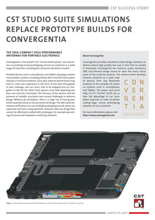
- 1. www.cst.com CST SUCCESS STORY CST STUDIO SUITE SIMULATIONS REPLACE PROTOTYPE BUILDS FOR CONVERGENTIA THE IDEA: COMPACT HIGH-PERFORMANCE ANTENNAS FOR PORTABLE ELECTRONICS Convergentia is the world’s first “virtual build factory”, and special- izes in providing virtual prototyping services to customers in a wide range of industries, including the consumer electronics market. Portable devices such as smartphones and tablets nowadays contain many wireless systems,including cellular,Wi-Fi and GPS.Each system requires a functional antenna, since poor antenna performance may lead to a bad user experience in the form of low data throughput or poor coverage, and can cause calls to be dropped and car navi- gation to fail. On the other hand, devices must look appealing and their size must be minimized. The thinness of the devices and the presence of metallic structures have caused challenges to antenna design. Without 3D simulations, there is a high risk of having poor antenna performance or clumsy industrial design.The alternative for antenna verification is to use multiple prototyping rounds,which are expensive and have a long lead time. However, there are things that cannot be effectively studied with prototypes, for example ground- ing structures and impedance matching networks. Figure 1 Simulated surface current distribution on the cellular antennas of a tablet at 0.9 GHz. About Convergentia Convergentia provides simulation-aided design solutions to devices where high quality, low cost or fast time to market is important. Convergentia has antenna, audio, mechanics, EMC and thermal design teams to cover the most critical parts of the customer product. The antenna team develops antenna solutions to a wide scale of devices, from tiny Bluetooth headsets to the complex LTE anten- na systems used in smartphones and tablets. The power and versa- tility of CST STUDIO SUITE let us take full advantage of our simu- lation expertise in order to deliver cutting edge virtual prototyping solutions to our customers. For more information, please visit http://www.convergentia.com
- 2. CST SUCCESS STORY www.cst.com For 3D simulation to be useful, the simulated results need to correlate with the measured data. A good agreement between the two is necessary to build confidence in the simulated data. Convergentia found that when discrepancies between the two arose, these were mainly due to the lack of similarity of the simu- lation model and the prototype, since it’s not practical or even pos- sible to 1-to-1 model all the complicated structures such as display, touch sensor or speaker. Material properties can also be unknown at the frequencies of interest. Therefore, it was up to antenna de- signer’s competence to judge how to model the parts that cannot be used directly from the mechanical 3D model. Convergentia’s engineers have many years of experience of modeling and design- ing electronic systems and sought a simulation tool that would let them make the most of their skills. For this reason, they turned to the powerful solvers of CST STUDIO SUITE®. THE CHALLENGE: ACCURATELY MODELING PCB LAYOUT AND GROUNDING STRUCTURES Most modern integrated antennas include either lumped components or RF switches for impedance matching, although due to the vast amount of frequency bands within LTE, chipset suppliers have started to include integrated antenna matching tuners in their circuitry.In the early phase of the R&D process, tuning elements can designed with circuit simulators, but for a working prototype, layout simulations are a must.This is especially important at higher frequencies (f > 1.7 GHz), when layout parasitic effects can become dominating. Traditionally, antenna tuning is done with network analyzer by opti- mizing the return loss of the antenna.Without a matching network, a good impedance matching usually also ensures good radiation properties. The efficiency of the antenna can be checked in an an- echoic chamber. This design process cannot be used for antennas with a matching network, because good impedance matching may consider more the losses in the network than good radiation of the antenna.With combined antenna and layout simulations,engineers can avoid additional PCB design rounds and skip the tedious and slow antenna tuning process. S11 [dB] Frequency [MHz] Sim Meas 0 -3 -6 -9 -12 -15 -18 -21 2000 2180 2360 2540 2720 5100 5280 5460 5640 58206000 6180 6360 4920 Total efficiency [dB] Frequency [MHz] Sim Meas 0 -1 -2 -3 -4 -5 -6 -7 -8 -9 -10 2000 2180 2360 2540 2720 5100 5280 5460 5640 58206000 6180 6360 4920 Figure 2 Uncertainties in material properties and component values leads to variation between the virtual prototype and the measured data (here for the Wi-Fi antenna). This means that accuracy is paramount in material characterization... S11 [dB] Frequency [MHz] Meas, 8n2 Sim with 8n2 Sim, 6n8 0 -3 -6 -9 -12 -15 780 800 820 840 860 900 880 920 940 960 980 Total efficiency [dB] Frequency [MHz] 0 -1 -2 -3 -4 -5 -6 -7 -8 -9 -10 -11 -12 Meas, 8n2 Sim, 8n2 Sim, 6n8 780 800 820 840 860 900 880 920 940 960 980 Figure 3 Simulated and measured S11 (top) and radiation efficiency (bottom) of the primary cellular antenna for two different matching circuit configurations.Tuning component values and material properties against measurement allows much better agreement to be achieved.
- 3. CST SUCCESS STORY www.cst.com Antennas require a proper ground plane in order to function cor- rectly. This can be difficult to realize in small device with several separate metal parts. Creating a good ground plane on a device means that the metal parts should be connected together so that maximal antenna performance is achieved. If grounding structure is not properly designed, it may result in insufficient bandwidth or there may be unintentionally created RF traps, which increase the antenna loss several decibels. These kind of lossy resonances are well-known to antenna designers and are very difficult to track and correct in prototypes. It may take weeks to find the cause of these problems, and a new prototyping round would be needed in order to fix the problem. Simulation made it possible designs to be examined without the cost of constructing a prototype, and field visualization allows resonant components to be identified by eye. Figure 4 A physical prototype of a tablet with several antennas (left) and the equivalent simulation model (right). Figure 5 (Top) The unmatched cellular antenna. (Bottom) The layout of the cellular antenna matching circuit, with four components.
- 4. www.cst.com CST SUCCESS STORY THE RESULT: ACCURATE VIRTUAL PROTOTYPES OF REAL SYSTEMS. Figure 4 shows a tablet prototype constructed by Convergentia with primary and secondary cellular antennas, as well as GPS and Wi-Fi antennas.The cellular antennas are of flex type mounted on a plastic antenna carrier, with small PCBs for antenna impedance matching and for feeding clips (Figure 5). The GPS antenna is etched on a sepa- rate PCB and Wi-Fi antenna is of a ceramic type (Figure 6). Convergentia found that the correlation of simulation and measure- ment was very good. Impedance matching was made with two coils and two capacitors. Convergentia found that differences between the simulation and the measurement were caused by differences be- tween the model and the physical reality: The material properties of the ceramics were unknown as well as the details of the PCB ground- ings, which lead to some discrepancies in Wi-Fi antenna frequency response (Figure 2).With slight tuning of the antenna and the materi- al properties, they found the expected performance.The primary cel- lular antenna simulation results correlation with the measurement was very good as well (Figure 3). With virtual prototyping, the number of prototype rounds were reduced together with the device development time. This speed- up came from two factors. First, there was no need for mechanical changes or PCB changes due to antenna performance issues during physical prototyping. Only fine tuning was needed in order to get all the potential from the antenna into use. Second, because all anten- nas worked as constructed, testing of other areas can begin without waiting for the antenna designers to get antennas working first. For example,EMC and data throughput tests can be started immediately. The prerequisite for the successful virtual build is that the simula- tion model corresponds with the upcoming prototype including the matching network layout and grounding structure of the device. The combination of the powerful CAD import tools and accurate solver technologies in CST STUDIO SUITE, together with Convergentia’s simulation expertise, allowed them to implement an effective virtual prototyping workflow. “The power and versatility of CST STUDIO SUITE let us take full advantage of our simulation expertise in order to deliver cutting-edge virtual prototyping solutions to our customers” Dr Sami Hienonen Technology Manager, Convergentia Ltd Figure 6 The GPS and Wi-Fi antennas.