
Recommended
Recommended
More Related Content
Similar to 4 ways to match antenna debug -C&T RF Antennas Inc
Similar to 4 ways to match antenna debug -C&T RF Antennas Inc (20)
More from Antenna Manufacturer Coco
More from Antenna Manufacturer Coco (20)
Recently uploaded
Recently uploaded (20)
4 ways to match antenna debug -C&T RF Antennas Inc
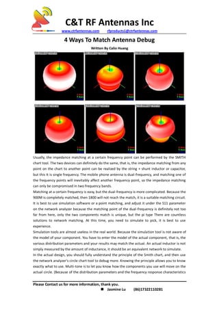
- 1. C&T RF Antennas Inc www.ctrfantennas.com rfproducts1@ctrfantennas.com Please Contact us for more information, thank you. Jasmine Lu (86)17322110281 4 Ways To Match Antenna Debug Written By Calio Huang Usually, the impedance matching at a certain frequency point can be performed by the SMITH chart tool. The two devices can definitely do the same, that is, the impedance matching from any point on the chart to another point can be realized by the string + shunt inductor or capacitor, but this It is single frequency. The mobile phone antenna is dual-frequency, and matching one of the frequency points will inevitably affect another frequency point, so the impedance matching can only be compromised in two frequency bands. Matching at a certain frequency is easy, but the dual-frequency is more complicated. Because the 900M is completely matched, then 1800 will not reach the match, it is a suitable matching circuit. It is best to use simulation software or a point matching, and adjust it under the S11 parameter on the network analyzer because the matching point of the dual-frequency is definitely not too far from here, only the two components match is unique, but the pi type There are countless solutions to network matching. At this time, you need to simulate to pick, it is best to use experience. Simulation tools are almost useless in the real world. Because the simulation tool is not aware of the model of your component. You have to enter the model of the actual component, that is, the various distribution parameters and your results may match the actual. An actual inductor is not simply measured by the amount of inductance, it should be an equivalent network to simulate. In the actual design, you should fully understand the principle of the Smith chart, and then use the network analyzer's circle chart tool to debug more. Knowing the principle allows you to know exactly what to use. Multi-tone is to let you know how the components you use will move on the actual circle. (Because of the distribution parameters and the frequency response characteristics
- 2. C&T RF Antennas Inc www.ctrfantennas.com rfproducts1@ctrfantennas.com Please Contact us for more information, thank you. Jasmine Lu (86)17322110281 of the components, the movement of the actual part on the chart and the movement of your theoretical calculation will be different). Dual-frequency matching is indeed a compromise process. You must add one piece to be purposeful. In the case of GSM and DCS dual-band, if you want to adjust GSM and don't want to change DCS, you should choose the way of a series capacitor and shunt inductor. Similarly, if you want to adjust the DCS, you should choose the string inductor and capacitor. In theory, two parts need to be adjusted for one frequency point, so the actual mobile phone or mobile terminal usually arranges the matching circuit according to the following rules: for simpler, the antenna space is larger, the reflection is originally smaller, and the Pai type is used (2 and one String), such as conventional candy bar phones, conventional clamshell machines; slightly more complicated with double L-type (2 strings 2 and): For more complicated, L+Pai type (2 strings 3 and 3), such as a mobile phone with a whip antenna. Keep in mind that matching circuits can reduce reflections but introduce losses. In some cases, although the standing wave ratio is better, the efficiency of the antenna system will decrease. Therefore, the design of the matching circuit is somewhat taboo; for example, in the matching circuit of the GSM and DCS mobile phones, the series inductance is generally not more than 5.6 NH. Also, when the reflection of the antenna itself is relatively large and the bandwidth is insufficient, it is seen on the smith diagram that the boundary point of each frequency band is large from the center of the circle, and generally the matching does not improve the radiation. The antenna's reflection index (VSWR, return loss) is generally used as a reference during the design process. The key parameters are transmission parameters (such as efficiency, gain, etc.). Some people emphasize the return loss, r is -10dB, the standing wave ratio is less than 1.5, it does not make sense. The SWR standing wave ratio only describes the degree of matching of the ports, that is, the degree of impedance matching. The matching is good, the SWR is small, and the power reflected back from the antenna input port is small. If the matching is not good, the power that is reflected back will be large. As for the part of the power that enters the antenna is not radiated, you are not sure. The efficiency of the antenna is the ratio of the total power radiated to space to the total power at the input port. So SWR is good, can't judge the antenna efficiency must be high (take a 50ohm matching resistor to connect, SWR is good, but there is radiation?). However, the SWR is not good, and the power of the reflection is large, and it can be confirmed that the efficiency of the antenna must not be high. SWR is a necessary but not sufficient condition for antenna efficiency. Good SWR and high radiation efficiency are necessary and sufficient conditions for high antenna efficiency. When the SWR is the ideal value (1), the port is ideally matched, and the antenna efficiency is equal to the radiation efficiency. In today's mobile phones, the space of the antenna is compressed smaller and smaller, at the expense of the performance of the antenna. For some multi-frequency antennas, even the VSWR has reached 6. In the past, we used more external antennas, and the average efficiency was lower at 50%. Now the efficiency of 50% or more is very good! Take a look at the mobile phones on the market, even if it is a famous company, such as Nokia, it is less than 20% efficient. Some mobile phones (sliding, rotating) are only about 10% efficient at certain frequencies. I have seen several test reports of built-in antennas for mobile phones. The antenna efficiency is
- 3. C&T RF Antennas Inc www.ctrfantennas.com rfproducts1@ctrfantennas.com Please Contact us for more information, thank you. Jasmine Lu (86)17322110281 basically around 30-40%. At that time, I felt that it was really bad enough (compared to the microstrip antenna I designed), and it seems to be okay now. However, in actual engineering, it seems that the loss due to S11 and the loss of the matching circuit are counted in the efficiency. According to the antenna principle, only the dielectric loss (including the substrate caused by the magnet in the mobile phone) and the metal loss (although very small) ) is in the loss of the antenna, and the loss of the return loss and matching circuit should not be recorded. But engineering is engineering, so it's easy to test. Right, add another sentence, software simulation is helpful to the project to a certain extent: Of course, the accuracy of the simulation results cannot be compared with the test, but the antenna performance obtained by parameter scanning simulation is still useful with the trend of the parameters. This is much faster than getting data through testing, especially for some parameters that are not commonly used. "The simulation tool has no use in actual engineering", which means that when designing the matching circuit, it is more specific when designing the dual-band GSM and DCS mobile phone antenna matching circuit. If you understand this sentence alone, it is undoubtedly wrong. In fact, I have been using HFSS for antenna simulation, and the results are based on simulation results. By the way, welding components is really a laborious thing, and there are methods. The so-called practice makes perfect. Large companies may give you a special welder, so you may just have to say what to weld. However, what we are discussing here is how to effectively complete the design of the matching circuit. Pay attention to effectiveness! Validity includes the time spent and the accuracy of the components selected. If there is no hands-on experience, only a matching design is made by software simulation but the actual antenna input is used. I can say that in all likelihood your design will not be used, even different from your imagination! In the actual design, there is another situation that you can't consider in the simulation (unless you measure it beforehand). That is the effect of the distribution parameters on the PIFA. Since the height of the antenna is getting smaller and smaller, and the matching circuit is either below (inside) or below (outside) the antenna, anyway, the addition of an actual component introduces a change in the distribution parameters in practice. Especially if the board layout is not good, this effect will be obvious. In actual welding, even if one piece is not welded well, re-welding will bring about a change in impedance. Therefore, in the design of PIFA, we usually do not use matching circuits (or 0ohm matching). This requires you to carefully adjust and optimize your antenna. In general, it is easier to implement today's flexible circuit board design (Flexfilm) because it is easier to modify the radiation film. It is relatively more difficult to stamp a metal for another design that is used more. First, the hardness is large, and space cannot be fully justified by the limitations of the process. Second, it is difficult to modify the design of the radiation sheet once the mold is formed. There is no great use of simulation tools in matching designs. Not many people can use simulation tools to calculate matches. Besides, is there any big effect on how to measure it? The engineering is fast and accurate. Simulation for simulation has no practical meaning. In order to get a 2, 3, up to 5 pieces of matching, you can build a model of inductance and capacitance, which is not worth it. Also, how do you consider the change in the distribution parameters of the PIFA match I mentioned above? Earlier I also said that some of the taboos of matching circuits are
- 4. C&T RF Antennas Inc www.ctrfantennas.com rfproducts1@ctrfantennas.com Please Contact us for more information, thank you. Jasmine Lu (86)17322110281 not derived from theory and are entirely derived from practice. Because the antenna is designed to improve its radiation efficiency (total efficiency)! I have not succeeded in finding an accurate matching circuit (so that GSM, DCS) dual-frequency through the simulation tool within 1 hour. (In practice, the error method is ok). When dealing with the practical application of the RF system, there are always some very difficult tasks, and matching one of the different impedances of the cascading circuits is one of them. In general, the circuits that need to be matched include the match between the antenna and the low noise amplifier (LNA), the match between the power amplifier output (RFOUT) and the antenna, and the match between the LNA/VCO output and the mixer input. The purpose of matching is to ensure that the signal or energy is effectively transferred from the "signal source" to the "load". At the high-frequency end, parasitic components (such as inductance on the wire, the capacitance between the layers, and resistance of the conductor) have a significant, unpredictable effect on the matching network. When the frequency is above tens of megahertz, the theoretical calculations and simulations are far from satisfactory. In order to get the appropriate final results, the RF test in the laboratory must be considered and properly tuned. The calculated value is used to determine the type of structure of the circuit and the corresponding target component value. There are many ways to match impedance, including 1• Computer Simulation: Because this type of software is designed for different functions and not just for impedance matching, it is more complicated to use. Designers must be familiar with entering large amounts of data in the correct format. Designers also need the skills to find useful data from a large number of output results. In addition, circuit emulation software cannot be pre-installed on a computer unless the computer is specifically built for this purpose. 2• Manual calculation: This is an extremely cumbersome method because it requires a longer ("several kilometers") calculation formula and the processed data is mostly plural. 3• Smith chart: The Smith chart not only finds the matching network for maximum power transmission but also helps designers optimize the noise figure, determine the quality factor and perform stability analysis. 4• Experience: This method can only be used by people who have worked in the RF field for many years. In short, it is only suitable for experienced experts. In fact, a true engineer should not only have theoretical knowledge but should also have the ability to solve problems using various resources. It's easy to add a few numbers to a program and get results. It's especially convenient when you have a problem that is complicated and not unique. However, if you can understand the basic theories and principles used in the working platform of a computer and know their origins, such an engineer or designer can become a more comprehensive and trustworthy expert, and the results are more reliable.