SlideShare a Scribd company logo
1 of 24
Download to read offline
Phone Number: 1-800-550-0280
Contact Email: contact@tacunasystems.com
Website: https://tacunasystems.com/
Force Measurement Glossary
A
 A2LA:The acronym for the American Association for Laboratory Ac-
creditation. It is the only independent, non-profit, internationally
known accreditation body in the US that offers a full range of compre-
hensive laboratory and laboratory-related accreditation services and
training.
 Accelerometer:This is a device for measuring acceleration. The force
causing the acceleration of a body is a product of the body mass m
and the acceleration a. This is shown mathematically below. This
principle makes possible the force measurement of vibrating masses
under the influence of a dynamic force by using accelerometers.
Accelerometer-force measure-
ment
Accuracy:The degree to which the output of the measuring instrument con-
forms to the actual value. In engineering, the accuracy of an instrument is
the greatest horizontal deviation of the output responses from the calibra-
tion line.
Active Transducers:A transducer whose output power is supplied mostly by
an external source of energy such as electrical energy. A good example of
this is the strain gauge incorporated in a Wheatstone bridge to cause a
voltage output due to changes in its resistance, the voltage output depends
on the excitation voltage.
Air Supply Regulator: The opening on a pneumatic load cell that regulates
the supply of air into the confined space of the load cell’s cylinder. It is lo-
cated close to the bottom of the load cell, below the diaphragm and con-
trolled by a valve.
Alloys: An alloy is a metal made from the combination of two or more met-
als to give better or the desired properties. Such properties might include
greater strength, greater resistance to corrosion, thermoelectric properties
etc. They form a majority of the raw materials from which force measure-
ment instruments are made. They include Nickel alloys, aluminum alloys,
zinc-based alloys, copper alloys etc.
Ambient Conditions: These are the weather or atmospheric conditions of
the environment in which measurements are performed. They include tem-
perature, humidity, and air pressure
Amplifier: The electronic device that amplifies the magnitude of the electri-
cal output of a transducer. Most transducers produce output electrical sig-
nals that are very small in magnitude usually in the order of millivolts. This
small signal cannot be used directly for processes such as system control
or even display, hence an amplifier is used to boost the signal. The most
commonly used and efficient amplifier for force measurement is the Instru-
mentation Amplifier.
Analog Circuit: An electronic circuit that deals or handles continuously vary-
ing signal called analog signals for the purpose of conveying information
through changes in current, voltage or frequency. Old instruments relied on
this type of circuit, but in modern instruments, they are used in combination
with digital circuits to give a more accurate result.
Analog Instrument: The category of measurement instruments that consists
basically of an input transducer, signal conditioners that amplify and filter
the signal and output elements such as displays. The input transducer con-
verts the analog signal into an equivalent analog electrical signal that has
to be amplified, with electrical noise filtered off and then displayed to indi-
cate the quantity of the analog signal.
Analog-Digital-Converter: An electronic systems that convert the analog out-
put of force transducers into digital signals. It is abbreviated as ADC and
consists of elements such as anti-aliasing filter circuits, sample and hold
circuits, and digital encoders. There are also different types such as the
flash ADC, successive approximation ADC, and sigma-delta ADC.
Angular Load Concentric: The load applied in a way that its central axis is
concentric with the primary axis of the load application point but at an angle
with respect to the primary axis.
Angular Load Eccentric: The load applied in a way that its central axis is ec-
centric with the primary axis of the application point and at an angle with re-
spect to the primary axis.
ANSI: The acronym for the American National Standards Institute. It is a
non-profit private organization that oversees the development of voluntary
consensus standards for products, services, processes, systems, and per-
sonnel in the US. Some of these standards apply to force measuring instru-
ment such as load cells.
Anti-Aliasing Filter: The electronic circuit that bandlimits the output of a
transducer to frequencies below the Nyquist frequency. This is so that ali-
asing would not occur when the signal is being converted back to its analog
form by a DAC. This is present in modern digital instruments.
Application Point: The point of application of the load/force or weight to be
measured by the instrument. It normally should have a loading platform
fixed to it so that the load is equally distributed and transmitted to the force
measurement transducer.
Automation: The creation and application of technology to monitor and con-
trol the production and delivery of products and services. This is one of the
vast applications of a force measuring instrument.
Axial Alignment: The alignment of the applied force or load along the trans-
ducer’s principal axis. This is very important in the design and installation of
an accurate force measurement system. A good force measurement sys-
tem that measures a single force component should be insensitive to or-
thogonal force components.
Axial Direction: The direction parallel to the axis of a body
Axial Load: The load that acts parallel to the axis of the platform or point of
application.
Axial Load
Axial Thrust: A propelling force that is applied along the axis of a body in or-
der to push the body against a platform towards an opposite direction. It is
the type of driving force generated by the propulsion system of an airplane
and a pogo stick.
B
 Bonded Resistive Foil: A thin piece of a metal strip attached to a struc-
tural member of an instrument or bonded to a non-conductive back-
ing. This describes a strain gauge.
 Bleed Valve: A valve attached to the body of the diaphragm of a pneu-
matic load cell. Its movement with respect to the deflection of the dia-
phragm by the external load closes and opens the outlet nozzle of a
pneumatic load cell.
 Bourdon Tube: The tube that connects the outlet of a pressure trans-
ducer to the pressure gauge. It transmits the pressure (force) in the
hydraulic load cell to the gauge.
 Bulk Micromachining: The MEM fabrication technique which describes
a subtractive process that uses etching to create large grooves, pits,
and channels on a substrate. Bulk micromachining is majorly used in
producing pressure sensors and accelerometers.
C
 Calibration: Calibration is the comparison of the reading of the force
measurement instrument to a known standard and the maintenance
of the evidentiary chain from that standard. It is also called traceabil-
ity and it plays a great role in eliminating the systematic error.
 Calibration Curve: A graph showing how the analytical response of
the instrument changes with the applied force or load. There are sev-
eral methods used in plotting this curve, one of which is finding the
straight line that best fits the scattered set of readings.
 Calibration Weights: The sets of known weights used when calibrating
a weighing instrument so as to ensure the accuracy of future results.
The weight sets consists of different sizes, with the output for each
applied weight forming a part of the reading to be plotted as a calibra-
tion curve. Check Out: Calibration Weights at Tacuna Systems
 Capacitive Load Cell: A load cell that causes the capacitance of the
transducer to vary with the stimulus. The changes in capacitance are
converted into electrically measurable quantities such as voltage,
which then shows the equivalent size of the force or load being
measured. This type of load cell demands electronic circuitry but its
design is mechanically simple and also very sensitive to the input sig-
nal.
 CE: The abbreviation of the French phrase “Conformité Eu-
ropéene“ which means “European Conformity” in English. This mark-
ing shows that an instrument complies with the requirements of the
European health, safety, and environmental protection legislation.
 Load Cell Indicators: The devices that provide high accuracy output
and allow easy amplification and display of the measured load
(force/weight). They include LCD and LED displays for easy reading
of measurements.
 Center Of Mass: The unique location on the body at which the total
mass of this body acts. The total mass of a body is assumed to be
fully concentrated at its center of mass.
 Centrifugal Force: The type of force that acts on a body that is in a cir-
cular motion. The force is directed away from the center of rotation of
the body.
 Certificate of Conformity: A document given by a competent authority
to original equipment manufacturers showing that their equipment,
products or services meet the required specifications. These specifi-
cations include a set of regulatory, technical and safety requirements.
 CMRR: The acronym for Common mode rejection ratio of an opera-
tional amplifier. It is the ratio of the differential gain to the common
mode gain. Simply put, it describes the ability of the operational am-
plifier to maximize the differential gain at the expense of the common
mode gain. It is normally quoted in dB.
 Common Mode Signals: These are identical signal components on the
inverting and non-inverting inputs of an instrumentation amplifier.
Common mode signals are noise signals that are induced equally in
both input terminals, the input wires are always closely twisted to-
gether to help reduce the noise effects. This, therefore, means that
an ideal instrumentation amplifier will cancel out the common mode
signals and amplify only the differential signals between the two
wires.
 Compression Force: The physical force that acts inward on a body
and causes it to become compacted. This type of force is observed
when a spring is compressed and the physical dimensions and geo-
metric shape of the spring changes.
 Corrugated Plate Diaphragms: These are diaphragms that have
greater deflections, better linear characteristic curve, and improved
sensitivity when compared to flat diaphragms. They are majorly used
in high-pressure applications especially in pneumatic load cells.
 Creep: This depicts the change in the load cell output with time when
a constant load is placed on its point of application and all the ambi-
ent conditions are kept constant. This means that if a known constant
weight is placed on the load cell for a long time, the output reading
changes over time even though no weight is being added or re-
moved. The creep for a particular load cell is always specified in its
datasheet.
 Creep Recovery: This is the change of output following a step de-
crease in the applied force, usually from the rated load capacity to
zero-load. In other words, it is the change in the zero-load output of a
load cell after the removal of the rated load that has been applied for
a specific period of time. It is specified as a percentage of the rated
load capacity over a specific period of time.
D
 Data Acquisition: This is the process of measuring physical stimulus
(in this context, force, load or weight), converting the result into digital
signals and storing them in computer memory for later use or distri-
bution. Modern instruments are basically data acquisition systems
whose output can be stored in a computer or even transmitted over a
long distance remotely.
Data Acquisition
 Data Acquisition Rate: This is another name for Sampling rate.
 Data Filtering: The removal of unwanted noise signals from the data
being acquired so as to obtain an accurate reading.
 Datasheet: The document that shows the summary of the technical
and performance characteristics of an instrument. The details con-
tained in this document is very useful to engineers when designing a
system that requires the incorporation of the instrument. It is always
provided by the supplier or the OEM.
 Dead Load: The constant load in a structure due to the weight of its
structural members or accessories.
 Deformation: A change is the dimensions (length and area) of a mate-
rial when subjected to a stress or strain.
 Deflection: The change in the length of a structural member of a load
cell when subjected to a load. In a force-balance measuring instru-
ment, the load causes a deflection in the diaphragm and transmits
the applied load to the fluid or gas in the confined space. In a strain
gauge load cell, the deflection of the structural members transmits
the applied load by causing a strain to the strain gauge.
 Diaphragm: These are thin elastic plates that deform when subjected
to loading.
 Dielectric: The electrical insulator located between the two parallel
metallic plates of a capacitive transducer.
 Digital Instrument: The category of a measurement instrument that
deals with digital signals. It consists of the major elements present in
an analog instrument. However, it requires majorly that the analog
output from the input transducer be digitized by using an analog to
digital converter. The digital signal is then processed by using a digi-
tal signal processor to perform tasks such as filtering, multiplexing,
digital display etc. The instrument can also include a digital to analog
converter that generates an analog output equivalent to the original
output. Generally, modern-day instruments are digital.
 Digital Pressure Transducers: The pressure transducer whose output
is in form of a digital signal. Most pressure transducers use pressure
gauges to indicate the equivalent form of the quantity being meas-
ured. Digital types have digital displays and the output can be trans-
mitted over a long distance for remote monitoring of plants.
 Digital-Analog Converters: These are electronic circuits that converts
digital signals into analog signals. It is abbreviated as DAC. They
work in an opposite manner in comparison to ADCs. The most com-
mon types of DACs are the binary-weighted DAC and the R-2R lad-
der DAC.
 Drift: The random change in the output reading under constant load-
ing conditions. It is kind of similar to creep.
 Ductility: The ability of a metallic material to undergo plastic defor-
mation when subjected to stress. Plastic deformation is often used as
a technique to permanently record an applied force.
 Dummy Gauge: The passive temperature compensation resistor
placed on the arm adjacent to the active arm of a quarter-bridge
strain gauge setup. The dummy gauge eliminates the effects of tem-
perature on the strain measurement. This is because there are identi-
cal temperature changes in both the active strain gauge and the
dummy gauge.
 Dynamic Force: The type of force whose magnitude varies with time.
In measuring any instantaneous value, the force measurement instru-
ment must have a frequency response sufficient enough to follow the
changing force.
E
 Eccentric Loading: A loading condition in which the center of mass of
the applied load is not on the central or neutral axis of the load cell’s
application point. It is also called offset loading and it produces a
bending moment along with the axial stress generated by the eccen-
tric load.
The Eccentric Loading
 Eccentricity: The distance between the central axis of a transducer
central axis to the center of mass of the load.
 Elasticity: The ability of a material to undergo deformation under the
influence of a force (compressive or tensile) without losing its original
shape and size after the force is removed. This is true so far the ma-
terial is not stretched or deformed beyond its elastic limit. The elastic
limit once exceeded causes the elastic material to suffer permanent
deformation
 Electrical Excitation: The external electrical energy supplied to the in-
put terminals of the transducer to power its operations.
 Electrical Output: The electrical signal produced as the output of the
transducer in response to the applied load.
 Electrical Transducer: The sensor device that detects an external phe-
nomenon or stimulus (such as force, pressure, displacement, accel-
eration etc.) and transforms this into an equivalent analog electrical
signal. The output electrical signal is therefore proportional to the ap-
plied load, hence its value is quantified.
 Electrostatic Sensitive Device: These are parts or components of a
force measurement instrument that can be damaged by common
electrostatic charges which build upon the instrument operators, tools
and other types of conductors. It is abbreviated as ESD, which can
also stand for electrostatic discharge.
 EMC: The acronym for Electromagnetic compatibility. It is defined as
the ability of an instrument or a device to function satisfactorily in its
electromagnetic environment without introducing intolerable electro-
magnetic disturbances to anything in that environment. In other
words, for an instrument to be said to have an EMC, it must be able
to operate efficiently without interfering with other systems within a
specified electromagnetic environment.
 EMI: The acronym for electromagnetic interference. This is a form of
environmental pollution that can cause malfunctions of electrical and
electronic devices, can prevent proper use of the radio frequency
spectrum, can ignite flammable atmospheres and has a direct effect
on the human tissue. EMC practices help to control various forms of
EMI.
 Environmental Conditions: The environmental factors that influence
the operations of force measurement instruments. They are also
called ambient conditions. They include the atmospheric pressure,
ambient temperature, humidity etc.
 Error: The difference between the actual value of a force, load or
weight and the true value. In instrumentation, an error is always ex-
pressed as a percentage of the full-scale output. Measurement errors
are basically systematic errors and random errors.
 ESD: The acronym for electrostatic discharge. It is the sudden flow of
electricity between two materials at different potentials caused by the
imbalance of electrons between the two. The acronym can also mean
electrostatic sensitive device.
 Etching: The process of removing parts of a thin film deposited on a
substrate material. Etching is one of the steps involved in the produc-
tion of MEMs such as strain gauges. There are different types of
etching, but majorly they are dry and wet etching.
F
 Fatigue Life: The number of total full cycles of applied force which
may be applied before the measurement uncertainty will be altered
beyond specified limits.
 Feedback Amplifiers:These are electronic devices used to amplify the
output of a transducer employed in a feedback control system. The
transducer measures the output of a process and then converts it into
an electrical signal. The electrical signal, if weak, is amplified by a
feedback amplifier and compared with the reference input or set
point. Feedback amplifiers are instrumentation amplifiers.
 Field Calibration Methods: These are methods used to determine the
repeatability of the measurement process. These methods are very
important in process application, where repeatability is far more criti-
cal to the control system than the absolute accuracy of measure-
ments.
 Flapper: The other name for the bleed valve of a pneumatic load cell
 Flexural Bond Strength: The flexural strength of a bonded material. It
depicts the maximum amount of stress experienced by the bonded
material at its moment of yield or fracture.
 Foil Strain Gauge: A type of strain gauge that consists of a metal foil
pattern mounted on an insulating backing or carrier. It is constructed
by bonding a sheet of thin rolled metal foil on a backing sheet. The
patterns on the gauge are produced by photo-etching.
 Force Calibration: The process of calibrating a force measurement in-
strument. It involves carrying out traceable measurements. Check
out: Load Cell Calibration Service by Tacuna Systems
 Force Measurement Methods:
 Ductility: The techniques and principles employed in the design and
of force measurement instruments. Some of the commonly employed
methods are lever-balance methods, force-balance methods, pres-
sure measurement, acceleration measurement and the use of elastic
elements. You may find helpful: Force and Weight Measurement Re-
sources You Can Refer To
 Force Transducer: The device that transforms an applied force into an
equivalent electrical output signal
 Force-Balance Systems: The measurement systems that employ the
use of feedback systems to ensure that the output electrical signal is
directly proportional to the applied force. These systems give high
stability, high accuracy and are suitable for measurement of dynamic
and static force.
 Formal Calibration: The calibration process that is normally performed
by approved laboratories, where the instrumentation used is periodi-
cally calibrated and traceable to primary standards; the operators are
well trained in calibration techniques, the temperature is controlled,
and atmospheric pressure and humidity accurately measured.
 Frequency Response: The highest sinusoidal frequency component of
an applied force that the force measurement instrument can measure
to a specified satisfactory accuracy.
 Full-Bridge Strain Gauge Load Cell: The strain gauge load cell that has
four strain gauges fixed into the four arms of a Wheatstone bridge cir-
cuit. The strain gauges are arranged such that the two responding to
either compression or tensile forces are on adjacent arms.
Full-Bridge Strain Gauge Load Cell
 Full-Scale Output: This is the output of the force measurement system
at rated load capacity minus the output at zero-load. It is abbreviated
as FSO and also called the span or rated output.
G
 Gauge Factor: The ratio of the fractional change in resistance to the
fractional change in length. It is a very useful parameter for compar-
ing the quality of strain gauge transducers.
H
 Half-Bridge Load Cell: The strain gauge load cell that has two strain
gauges fixed into adjacent arms of a Wheatstone bridge circuit, to-
gether with circuit completion resistors.
 Hooke’s Law: The law states that the force needed to extend or com-
press a string by some distance is proportional to that distance. This
principle is applied in designing mechanical sensors that measure
forces by transforming the force into the deformation of an elastic
medium. Mathematically, the law is expressed as;
 Hydraulic Fluid: The medium by which the pressure generated by the
applied load is transmitted to the pressure gauge. The fluid is housed
in the confined space in a hydraulic pressure transducer.
 Hydraulic Load Cell: A type of mechanical, force-balance load cell de-
vice that measures pressure or load by using a piston-cylinder ar-
rangement. This arrangement uses a fluid housed in a confined
space in the body of the cylinder to transmit pressure to a pressure
gauge through a connecting tube. The pressure output on the gauge
then shows the equivalent size of the applied load. The pressure out-
put can also be a pressure transducer instead of a gauge.
 Hysteresis: The difference of output readings between the increasing
and decreasing forces at any given force. That is, it is the difference
between the readings of a load cell transducer as the load is in-
creased [from zero-load to its rated capacity] and the readings as the
load is decreased [from rated capacity to zero-load].
I
 IAQG: The acronym for the International Aerospace Quality Group. It
is an organization that focuses on the continuous improvement of the
processes within the supply chain to deliver consistently high-quality
products. A part of its objectives is to establish common quality
standards and requirements. These standards apply to various force
measurement instruments
 IEC: The acronym for the International Electro-Technical Commis-
sion. It is an international standards organization that prepare and
publishes international standards that prepares and publishes inter-
national standards for all electrical, electronic and related technolo-
gies
 Input Terminal Resistance: The resistance measured across the exci-
tation terminals of a force transducer at standard test conditions, with
zero-load, and with the output terminals open circuited.
 Insulation Resistance Tests: The test carried out when there are un-
stable readings and random changes in the zero balance point of the
load cell. It is done by connecting all the conductors together and
then the resistance between all the connected wires and the load cell
body is measured
 ISA: The acronym for The International Society of Automation. It is a
non-profit technical society for engineers, technicians, businesspeo-
ple, educators, and students, who work, study or are interested in in-
dustrial automation and pursuits related to it, such as instrumenta-
tion.
 ISO: The acronym for the International Organization for Standardiza-
tion. It is a global network of the world’s leading standardizers that
brings together experts from all over the world to develop Interna-
tional Standards. The organization issues the certificate of conformity
to OEMs.
L
 LCD: The acronym for Liquid Crystal Display.
 LED: The acronym for Light Emitting Diode.
 Load: This refers to forces, deformations, and weights exerted, ap-
plied or placed on a surface. A load is a vector quantity, meaning it
has magnitude and acts in a specific direction.
 Load Cell: The sensor device that is used to detect a physical param-
eter or stimulus (force and pressure) and then produce an output that
is proportional to the stimulus. Load cells are generally linear sys-
tems but they are of different types and designs with the most com-
mon ones being hydraulic load cell, strain gauge load cell and pneu-
matic load cell. Read: How Do Load Cells Work?
 Load Cell Accessories: The materials that supplement load cells and
they include load cell cables and connectors, lifting, crane or tension
eye bolts, mounting kits and spacers for proper installation and sup-
port of load cells. Check Out: Load Cell Accessories at Tacuna Sys-
tems
 Load Cell Materials: The raw materials from which load cell devices
and their parts are fabricated. These materials include stainless steel,
hydraulic oil, phosphor bronze, beryllium bronze, plastics, glass,
basic metals, copper-nickel, nickel-chromium, platinum-tungsten al-
loy. The materials are always chosen based on desired properties
such as strength, weight, malleability, corrosion resistance, thermal
conductivity, electrical conductivity, machining, viscosity, volatility,
thermal expansion etc. Read: An Important Guide to Load Cell Materi-
als
 Loading Platform: The interface through which force/load is applied to
a force transducer. Depending on the design, there may be upper
and lower loading surfaces of a compression force transducer or the
upper and lower screw threads of a tension device. Load cells should
come with mounting kits that serve as loading platforms and ensure
appropriate force distribution on the device.
 LVDT: The acronym for Linear Voltage Differential Transformer. It is
an inductive transducer that consists of a primary winding and two
secondary windings wound around a magnetic core. The primary
winding is excited by an AC voltage, the movement of the magnetic
core then varies the mutual inductance of the two secondary wind-
ings with respect to the primary coil. The device uses the basic princi-
ples of magnetics to detect a load and then produce an output volt-
age proportional to the load.
M
 Machine Operator: The skilled personnel that has been trained to op-
erate a machine or device such as a force measurement instrument.
 Magneto-Elastic Load Cell: The force transducer that operates on the
effect that when a ferromagnetic material is subjected to mechanical
stress, the magnetic properties of the material are altered and the
change is proportional to the applied stress. They are majorly used in
rough and electrically disturbed environments.
 Manometer: The device that measures the pressure in a liquid. It is
commonly used in conventional hydraulic load cells.
 Mechanical Vibrations: These are oscillations that repeat within a time
period. There are different classes of vibration: free (undisturbed) and
forced (disturbed), damped and un-damped (has negligible or no
damping), nonlinear and linear, and random (unpredictable) and de-
terministic.
 MEMS: The acronym for Micro-Electro-Mechanical-Systems. They are
miniaturized electro-mechanical elements that are made using micro-
fabrication techniques.
 Micromachining: This refers to techniques for fabrication of 3D struc-
tures on the micrometer scale. It is a new trend in manufacturing that
seeks to meet the demands for micro components for reduced size
and weight applications. MEMs are manufactured using microm-
achining techniques such as photolithography, laser micromachining,
micro-electronic discharge machining etc.
 Microcontrollers: : A small computer unit on a single integrated circuit.
The computer system consists of a processor, memory and other pe-
ripherals. They are embedded in the design of modern force meas-
urement instrument for the purpose of performing digital signal pro-
cessing. The microcontrollers have analog to digital input terminals
and digital output terminals that can connect to actuators and display
devices to control an industrial process or display the result of meas-
urements.
 Modulus Of Elasticity: The measure of the resistance of a material to
elastic deformation when subjected to a load.
 mV: : This means Milli-Volt. The raw unconditioned analog output of
an electrical transducer is always a weak signal of the order of milli-
volts.
N
 Natural Frequency: The rate at which a body vibrates when it is not
disturbed by an external force. In simple terms, when a body is given
an initial displacement force and the force is withdrawn, the body
starts oscillating about its initial equilibrium position and continues to
oscillate on its own accord with any external force acting to keep it in
motion.
 Necking: This is a mode of tensile deformation where relatively large
amounts of strain localize (permanently) disproportionately in a small
region of the material. The neck constitutes a decrease in the local
cross-sectional area and it can break when enough strain is applied
across it.
 NEPSI: The acronym for the National Supervision and Inspection
Center for Explosion Protection and Safety of Instrumentation. It is a
government approved establishment that is mainly engaged in re-
search and development of explosion protection technology, testing,
verification and certification of electrical equipment for use in explo-
sive atmospheres, as well as explosion protection and safety supervi-
sion and assessment of engineering projects.
 Nominal Displacement: The measure of the deformation of the force
transducer when the rated load is applied. It is a factor that deter-
mines the stiffness of the transducer.
 Nominal Force: The rated force or load that specifies the maximum
capacity of the force transducer. It is the same thing as full-scale out-
put. It is always specified in the instrument’s datasheet.
 Nominal Temperature: The rated temperature range in which the force
transducer works satisfactorily within the specifications in its
datasheet.
 Non-Linearity: Linearity: This describes the deviation of the true in-
put/output curve from the idealized straight line approximating it. Ide-
ally, the output of a force transducer is meant to be proportional to
the applied load, however, in practical measurement, there exist dis-
crepancies called non-linearity error.
 NPL: The acronym for the National Physical Laboratory, UK’s national
measurement institute.
 NTEP: The acronym for the National Type Evaluation Program.
O
 OEM: The acronym for Original Equipment Manufacturer. This is a
company that produces equipment and instruments such as a force
measurement device that may be marketed by another manufacturer.
 OIML: The acronym for the International Organization of Legal Metrol-
ogy
 OLED: The acronym for Organic Light Emitting Diode
 Operating Range Of The Excitation Voltage: The range of temperature
values within which a transducer can operate at its rated capacity
and perform satisfactorily within its specifications.
 Operating Temperature Range: This is the same as the Nominal or
rated temperature range.
 Output Resistance: The resistance measured on the output terminals
of a transducer at a standard temperature at zero-load and zero exci-
tation.
 Overload Stop: The mechanical device designed to prevent overload-
ing or overstressing of the transducer beyond its rated capacity.
P
 Piezoelectric Effect: This describes the ability of certain materials to
generate an electric charge in response to an applied mechanical
stress. Materials that exhibit this characteristic either occur naturally
or artificially synthesized. Natural piezoelectric materials include Ber-
linite, quartz, topaz and Rochelle salt, while artificial ones include
Barium Titanate and lead Zirconate.
 Piezoelectric Force Transducer: The transducer than uses the piezoe-
lectric effect to measure an applied force or load. It is shown below.
The applied force causes a proportional electrical charge to appear
on the faces of the piezoelectric element. It is an active transducer,
meaning the output power is supplied entirely by the input, hence a
piezoelectric transducer does not need an external electrical excita-
tion.
Piezoelectric
Force Transducer
 Pneumatic Load Cell: A type of mechanical, force-balance load cell
device that measures pressure or load by using a piston-cylinder ar-
rangement. This arrangement uses a volume of gas housed in a con-
fined space in the body of the cylinder to transmit pressure to a pneu-
matic pressure dial gauge. The pressure output on the gauge then
shows the equivalent size of the applied load. The pressure output
can also be a pressure transducer instead of a gauge.
 Precision: This describes the reproducibility of the measurement sys-
tem.
 Pressure Transducer: The device that senses physical pressure and
transforms it into an equivalent output signal, usually in an electrical
form. The pressure transducer can replace the pressure gauge pre-
sent at the pressure output of a pneumatic or hydraulic load cell. It of-
fers more accurate readings than a pressure gauge.
 Primary Axis: The axis along which the applied load or face is de-
signed to act. It is situated around the point of application of the force
measurement instrument.
Q
 Quarter-Bridge Load Cell: The load cell type that has a single strain
gauge fixed into an arm of a Wheatstone bridge circuit together with
completion resistors and a dummy gauge for temperature compensa-
tion.
R
 Random Errors: The errors that depict variations in output readings,
that even though clearly observed, are difficult to explain. In engi-
neering, probability and statistical tools are used in estimating ran-
dom error. It is assumed that the random signal or error belongs to
an ensemble of signals, with each signal having its own probability of
occurrence. The probability distribution of the error is uniform about
the mean.
 Rated Capacity: This is the full-scale output.
 Recalibration: The process of performing calibration after the initial
calibration is done. Frequent recalibration should be performed at
regular intervals of about 1 year to ensure that the instrument pro-
vides accurate measurements.
 Reference Standard: A force measurement instrument whose perfor-
mance characteristics are known in relation to a primary standard.
 Reliability: The probability of the instrument performing satisfactorily
under the stated conditions for a specified period of time.
 Repeatability: The measure of the agreement between the results of
successive measurements of the differences of the output of a force
measurement system for repeated applications of a given force in the
same direction and within the range of the calibration forces applied.
It shows the ability of a force measurement system to measure force
consistently.
 Reproducibility: The closeness of the agreement between the results
of the measurements of the same force carried out under changed
conditions of measurement
 Resistivity: The electrical resistivity is the property of a material to re-
sist the flow of electric current through. Mathematically, it is ex-
pressed as
Resistivity
 Resolution: The ability of the force measurement system to detect
and reliably indicate small changes in the characteristic of the meas-
urement result.
 ROHS: The acronym for the Restriction of Hazardous Substances.
 RS232: The acronym for the Recommended Standard 232, a stand-
ard communication protocol for networking a computer and periph-
eral devices (such as a digital measurement instrument) to allow se-
rial data exchange.
S
 Safe Over Range: The maximum load that can be applied to a force
transducer without causing plastic deformation to its elastic element.
 Semiconductor Gauge: A strain gauge type manufactured from strips
of semi-conducting silicon in either n-type or p-type. It exhibits special
characteristics such as high output, no creep, and hysteresis, long fa-
tigue life. They are widely used in force transducers, accelerometers,
and pressure sensors.
 Sensitivity: The rate of change of the output signal as the desired sig-
nal at the input varies. The sensitivity of a transducer allows us to
predict the output voltage from the knowledge of the excitation volt-
age and the value of the applied stimulus.
 Shear Force: The force that acts perpendicular to the longitudinal axis
of the body. It tends to divide the body along a plane parallel to an
opposing stress
 Shielding: This involves placing a conductive surface around the criti-
cal parts of the instrument’s circuit so that the electromagnetic field
which couples to it is attenuated. A good force transducer has a
shield wire as its fifth wire terminal.
 Shock Resistance Test: The test carried out when there are unstable
readings and random changes in the zero balance point of the load
cell. It is done by connecting all the conductors together and then the
resistance between all the connected wires and the load cell body is
measured.
 Shunt Calibration: The calibration of a load cell transducer by the in-
sertion of known shunt resistors into the appropriate arms of its
Wheatstone bridge circuit.
 Shunt-To-Load Correlation: The numerical difference between the out-
put readings obtained from shunt calibrations and the actual applica-
tion of loads.
 Signal Conditioning Circuit: The circuit that performs signal filtering,
amplification, and isolation to ensure a more accurate result is ob-
tained.
 Stabilization Period: The time interval required to ensure that any fur-
ther changes in the load to being measured is tolerable. Simply put, it
is the time required for the output readings to stabilize and maintain a
certain value before it is recorded as the actual output value.
 Standard Test Conditions: The ambient conditions under which meas-
urements should be performed. It is abbreviated as STC. The condi-
tions will include factors such as temperature, humidity, and pressure
for force measurements.
 Static load: A load whose size/magnitude does not change with time.
 Stiffness: The ability of a body to resist deformation when a load is
applied to it. It is similar to the young modulus.
 Strain: The fractional change in dimension (length). It is the ratio of
the change in length to the instantaneous or original length. It is also
called the Engineering Strain
 Strain Gauge: A resistive element that produces a change in its re-
sistance proportional to an applied mechanical strain.
 Strain Gauge Transducers: The transducer type that uses the strain
gauge as its underlying mechanism. It has the strain gauge(s) at-
tached to a structural, which undergoes deformation when a load is
applied to the load cell. It is the most common type of load cell found
in measurement devices all across various industries.
 Stress: The ratio of the force applied to the cross-sectional. When-
ever a material is loaded, a stress is generated within it that causes a
deformation in its geometric shape.
 Structural Member: The constituent part of force transducers that pro-
vides support and housing for other components. The geometric
shape of the structural member also determines the category to
which the load cell belongs. According to the shape of the structural
members, load cells can be beam load cells, disk load cells, S-
type, tension link load cell and miniature load cell.
 Summing Junctions: There are used for summing data output from
multiple load cells into a single output.
 System Requirements: The necessary and desired specifications and
standards that the force measurement system must meet. It is always
specified by the user, client or the expert designing the whole sys-
tem. When the system requirements are known, then the specific in-
strument that best matches these requirements are selected for use.
 Systematic Error: This is the error inherent in the operation of a force
measurement instrument. It can be eliminated through system cali-
bration.
T
 Tare Weight: The weight of an empty container or the loading plat-
form.
 TEDS: The acronym for the Transducer Electronic Datasheet. It con-
tains details about the technical and performance characteristics of
the transducer.
 Telemetry: An automated communication process that describes the
transmission of data or information between two geographical loca-
tions. In instrumentation, transmission is required to enable central-
ized supervisory data login, signal processing or control of large-
scale systems. Telemetry can be provided by electrical transmission
as well as pneumatic transmission. Pneumatic transmission is em-
ployed in a hazardous area where an electrical power failure can be
very disastrous.
 Temperature Compensation: This is carried out to eliminate the dimen-
sional changes caused by temperature changes in a transducer. To
cater to these unwanted thermal effects, self-temperature compen-
sated gauges are used. Dummy gauges can also be used so that the
thermal effects will cancel and be eliminated from the output.
 Tensile Force: The force that stretches or elongates the size of a ma-
terial
 Tensile Strength: The capacity of a material to withstand tensile forces
wanting to stretch the material.
 Thin Film Strain Gauge: The strain gauge type produced by evaporat-
ing thin films of metals or alloys onto an elastic element.
 Tolerance: The allowable maximum deviation from the standard spec-
ifications.
 Torque: The turning effect caused by a force acting at a distance on a
body. It is the product of the force and the perpendicular distance be-
tween the line of action of the force and the center of rotation at
which it is exerted.
 Torsional Modulus: The modulus of elasticity of a material when sub-
jected to a torque force.
 Traceability: This is another name for Calibration.
 Troubleshooting: The process of detecting, tracking, analyzing
and correcting faults in a measurement system. There are various
standard troubleshooting procedures to follow for each force meas-
urement instrument.
 True Strain: This is the natural logarithm of the Engineering Strain.
U
 Ultimate Elongation: This is the maximum elongation suffered by a
material at rupture when subjected to tensile forces
 Ultimate Strength: The maximum stress a material can withstand be-
fore it breaks.
 Unloaded Output Voltage: The electrical output voltage from the force
transducer under zero load or no load.
V
 Vibrating Wire Load Cell: The transducer that consists of a taut ferro-
magnetic wire that is excited into transverse vibrations by a drive coil.
These vibrations are detected by a pick-up coil. The drive coil and
pickup coil have magnetic cores and once the wire has been excited
to its resonant frequency for a given tension. This frequency is main-
tained by a self-oscillatory systems system formed between the two
coils. The resonant frequency is, therefore, a measure of the applied
force at that instant.
 Visual Displays: These are used to indicate either qualitative or quan-
titative events. A qualitative event means the presence or absence of
some signals. A quantitative event means the value of the signal.
LEDs and LCDs are the common types of visual displays.
W
 Wheatstone bridge: A circuit configuration that is majorly used to
measure electrical parameters such as resistance, inductance, and
capacitance. The configuration incorporates an excitations source,
four arms where passive components can be fixed and an output ter-
minal. It should be noted that In order to measure capacitance or in-
ductance, the normal Wheatstone bridge is modified but still follows
the same circuit configuration pattern.
 Wire Strain Gauge: The original type of resistance strain gauge,
though now widely replaced by foil and thin film strain gauges. It still
finds application in high-temperature transducers and stress analysis.
Y
 Young Modulus: The ratio of the stress caused by an applied force
acting over an area of a material to the strain.
Z
 Zero Balance: This is the default output signal of the transducer when
no load or zero-load is applied to it.
 Zero Offset: The difference between the zero-load specified in the in-
strument’s datasheet and the actual zero load output obtained by di-
rect measurement under zero-load conditions (removal of all weights,
loads and dead load).
Sources
1. Difference between Analog and Digital Circuits.
2. Definition of Analog Circuits
3. Instrumentation Systems
4. https://www.chegg.com/homework-help/definitions/mechanical-vibra-
tions-5
5. Instrumentation Reference Book, W. Boyes.
6. A Guide to the Measurement of Force, Andy Hunt.
Phone Number: 1-800-550-0280
Contact Email: contact@tacunasystems.com
Website: https://tacunasystems.com/

More Related Content

What's hot

Electrical measurements unit-1-measuring instruments
Electrical measurements unit-1-measuring instrumentsElectrical measurements unit-1-measuring instruments
Electrical measurements unit-1-measuring instrumentsRAGHU ENGINEERING COLLEGE
 
Ac and dc meters and kirchoff's laws
Ac and dc meters and kirchoff's lawsAc and dc meters and kirchoff's laws
Ac and dc meters and kirchoff's lawsNishkam Dhiman
 
ELECTRICAL MEASUREMENT & MEASURING INSTRUMENTS [Emmi- (NEE-302) -unit-1]
ELECTRICAL MEASUREMENT & MEASURING INSTRUMENTS [Emmi- (NEE-302) -unit-1]ELECTRICAL MEASUREMENT & MEASURING INSTRUMENTS [Emmi- (NEE-302) -unit-1]
ELECTRICAL MEASUREMENT & MEASURING INSTRUMENTS [Emmi- (NEE-302) -unit-1]Md Irshad Ahmad
 
Power factor improvement using upfc
Power factor improvement using upfcPower factor improvement using upfc
Power factor improvement using upfcUday Wankar
 
Reactive power consumption in modern power system
Reactive power consumption in modern power systemReactive power consumption in modern power system
Reactive power consumption in modern power systemRahuldey1991
 
IRJET- Improved IUPQC Controller to Provide Grid Voltage as a STATCOM
IRJET- Improved IUPQC Controller to Provide Grid Voltage as a STATCOMIRJET- Improved IUPQC Controller to Provide Grid Voltage as a STATCOM
IRJET- Improved IUPQC Controller to Provide Grid Voltage as a STATCOMIRJET Journal
 
Study and Performance Analysis of FACTS-incorporated Transmission Line
Study and Performance Analysis of FACTS-incorporated Transmission LineStudy and Performance Analysis of FACTS-incorporated Transmission Line
Study and Performance Analysis of FACTS-incorporated Transmission LineUnited International University
 
Power Flow Control using Quadrature Boosters
Power Flow Control using Quadrature BoostersPower Flow Control using Quadrature Boosters
Power Flow Control using Quadrature Boostersbalasubu2k
 
ASSESSMENT OF VOLTAGE FLUCTUATION AND REACTIVE POWER CONTROL WITH SVC USING PSO
ASSESSMENT OF VOLTAGE FLUCTUATION AND REACTIVE POWER CONTROL WITH SVC USING PSOASSESSMENT OF VOLTAGE FLUCTUATION AND REACTIVE POWER CONTROL WITH SVC USING PSO
ASSESSMENT OF VOLTAGE FLUCTUATION AND REACTIVE POWER CONTROL WITH SVC USING PSOKashif Mehmood
 
60232804 ppt-compensation-techniques-in-ac-transmission-system-using-c
60232804 ppt-compensation-techniques-in-ac-transmission-system-using-c60232804 ppt-compensation-techniques-in-ac-transmission-system-using-c
60232804 ppt-compensation-techniques-in-ac-transmission-system-using-cABHISHEK RAI
 
Measurement & Instrumentation (BE)
Measurement & Instrumentation (BE)Measurement & Instrumentation (BE)
Measurement & Instrumentation (BE)PRABHAHARAN429
 
Role of Flexible AC Transmission in Power System Contingency
Role of Flexible AC Transmission in Power System ContingencyRole of Flexible AC Transmission in Power System Contingency
Role of Flexible AC Transmission in Power System ContingencySayantan Datta
 

What's hot (20)

Electrical measurements unit-1-measuring instruments
Electrical measurements unit-1-measuring instrumentsElectrical measurements unit-1-measuring instruments
Electrical measurements unit-1-measuring instruments
 
FACTS Controller.
FACTS Controller.FACTS Controller.
FACTS Controller.
 
Reactive power management in india
Reactive power  management in indiaReactive power  management in india
Reactive power management in india
 
U4501117122
U4501117122U4501117122
U4501117122
 
Ac and dc meters and kirchoff's laws
Ac and dc meters and kirchoff's lawsAc and dc meters and kirchoff's laws
Ac and dc meters and kirchoff's laws
 
Load list calculation
Load list calculationLoad list calculation
Load list calculation
 
ELECTRICAL MEASUREMENT & MEASURING INSTRUMENTS [Emmi- (NEE-302) -unit-1]
ELECTRICAL MEASUREMENT & MEASURING INSTRUMENTS [Emmi- (NEE-302) -unit-1]ELECTRICAL MEASUREMENT & MEASURING INSTRUMENTS [Emmi- (NEE-302) -unit-1]
ELECTRICAL MEASUREMENT & MEASURING INSTRUMENTS [Emmi- (NEE-302) -unit-1]
 
Power factor improvement using upfc
Power factor improvement using upfcPower factor improvement using upfc
Power factor improvement using upfc
 
Eo35798805
Eo35798805Eo35798805
Eo35798805
 
Reactive power consumption in modern power system
Reactive power consumption in modern power systemReactive power consumption in modern power system
Reactive power consumption in modern power system
 
IRJET- Improved IUPQC Controller to Provide Grid Voltage as a STATCOM
IRJET- Improved IUPQC Controller to Provide Grid Voltage as a STATCOMIRJET- Improved IUPQC Controller to Provide Grid Voltage as a STATCOM
IRJET- Improved IUPQC Controller to Provide Grid Voltage as a STATCOM
 
Emi unit 1 ppt
Emi unit 1 pptEmi unit 1 ppt
Emi unit 1 ppt
 
Study and Performance Analysis of FACTS-incorporated Transmission Line
Study and Performance Analysis of FACTS-incorporated Transmission LineStudy and Performance Analysis of FACTS-incorporated Transmission Line
Study and Performance Analysis of FACTS-incorporated Transmission Line
 
Analog & digital measuring instruments
Analog & digital measuring instrumentsAnalog & digital measuring instruments
Analog & digital measuring instruments
 
Power Flow Control using Quadrature Boosters
Power Flow Control using Quadrature BoostersPower Flow Control using Quadrature Boosters
Power Flow Control using Quadrature Boosters
 
Transducers
TransducersTransducers
Transducers
 
ASSESSMENT OF VOLTAGE FLUCTUATION AND REACTIVE POWER CONTROL WITH SVC USING PSO
ASSESSMENT OF VOLTAGE FLUCTUATION AND REACTIVE POWER CONTROL WITH SVC USING PSOASSESSMENT OF VOLTAGE FLUCTUATION AND REACTIVE POWER CONTROL WITH SVC USING PSO
ASSESSMENT OF VOLTAGE FLUCTUATION AND REACTIVE POWER CONTROL WITH SVC USING PSO
 
60232804 ppt-compensation-techniques-in-ac-transmission-system-using-c
60232804 ppt-compensation-techniques-in-ac-transmission-system-using-c60232804 ppt-compensation-techniques-in-ac-transmission-system-using-c
60232804 ppt-compensation-techniques-in-ac-transmission-system-using-c
 
Measurement & Instrumentation (BE)
Measurement & Instrumentation (BE)Measurement & Instrumentation (BE)
Measurement & Instrumentation (BE)
 
Role of Flexible AC Transmission in Power System Contingency
Role of Flexible AC Transmission in Power System ContingencyRole of Flexible AC Transmission in Power System Contingency
Role of Flexible AC Transmission in Power System Contingency
 

Similar to A Complete Force Measurement Glossary

Force Sensor Data Acquisition
Force Sensor Data AcquisitionForce Sensor Data Acquisition
Force Sensor Data AcquisitionTacuna Systems
 
Measuring Forces in the Force Shunt
Measuring Forces in the Force ShuntMeasuring Forces in the Force Shunt
Measuring Forces in the Force ShuntTacuna Systems
 
indicatinginstruments-140114023522-phpapp01.pptx
indicatinginstruments-140114023522-phpapp01.pptxindicatinginstruments-140114023522-phpapp01.pptx
indicatinginstruments-140114023522-phpapp01.pptxHarsh24222
 
Indicating instruments
Indicating instrumentsIndicating instruments
Indicating instrumentsKausik das
 
All About Load Cell Weight
All About Load Cell WeightAll About Load Cell Weight
All About Load Cell WeightTacuna Systems
 
All About Electrical Connections of Force Transducers
All About Electrical Connections of Force TransducersAll About Electrical Connections of Force Transducers
All About Electrical Connections of Force TransducersTacuna Systems
 
Concepts of Reactive Power Control and Voltage Stability Methods in Power Sys...
Concepts of Reactive Power Control and Voltage Stability Methods in Power Sys...Concepts of Reactive Power Control and Voltage Stability Methods in Power Sys...
Concepts of Reactive Power Control and Voltage Stability Methods in Power Sys...IOSR Journals
 
CHapter 4 -Signal Conditioning.pptxyyhhhj
CHapter 4 -Signal Conditioning.pptxyyhhhjCHapter 4 -Signal Conditioning.pptxyyhhhj
CHapter 4 -Signal Conditioning.pptxyyhhhjteddiyfentaw
 
Iaetsd minimization of voltage sags and swells using dvr
Iaetsd minimization of voltage sags and swells using dvrIaetsd minimization of voltage sags and swells using dvr
Iaetsd minimization of voltage sags and swells using dvrIaetsd Iaetsd
 
Electrical testing equipment clamp meters- Usage, operations and Safety
Electrical testing equipment   clamp meters- Usage, operations and SafetyElectrical testing equipment   clamp meters- Usage, operations and Safety
Electrical testing equipment clamp meters- Usage, operations and SafetyAniruddha Kulkarni
 
REACTIVE POWER
REACTIVE POWERREACTIVE POWER
REACTIVE POWERJeetDatta3
 
Reactive Power : Problems and Solutions
Reactive Power : Problems and SolutionsReactive Power : Problems and Solutions
Reactive Power : Problems and SolutionsAbhinav Dubey
 
basic of measurement and instrumentation.
basic of measurement and instrumentation.basic of measurement and instrumentation.
basic of measurement and instrumentation.SACHINNikam39
 
Calibrating the Measuring Chain
Calibrating the Measuring ChainCalibrating the Measuring Chain
Calibrating the Measuring ChainTacuna Systems
 
Simulation and Modeling of Dynamic Voltage Restorer for Compensation Of Volta...
Simulation and Modeling of Dynamic Voltage Restorer for Compensation Of Volta...Simulation and Modeling of Dynamic Voltage Restorer for Compensation Of Volta...
Simulation and Modeling of Dynamic Voltage Restorer for Compensation Of Volta...IRJET Journal
 
IRJET-Simulation and Modeling of Dynamic Voltage Restorer for Compensation Of...
IRJET-Simulation and Modeling of Dynamic Voltage Restorer for Compensation Of...IRJET-Simulation and Modeling of Dynamic Voltage Restorer for Compensation Of...
IRJET-Simulation and Modeling of Dynamic Voltage Restorer for Compensation Of...IRJET Journal
 

Similar to A Complete Force Measurement Glossary (20)

Force Sensor Data Acquisition
Force Sensor Data AcquisitionForce Sensor Data Acquisition
Force Sensor Data Acquisition
 
Measuring Forces in the Force Shunt
Measuring Forces in the Force ShuntMeasuring Forces in the Force Shunt
Measuring Forces in the Force Shunt
 
indicatinginstruments-140114023522-phpapp01.pptx
indicatinginstruments-140114023522-phpapp01.pptxindicatinginstruments-140114023522-phpapp01.pptx
indicatinginstruments-140114023522-phpapp01.pptx
 
Indicating instruments
Indicating instrumentsIndicating instruments
Indicating instruments
 
K044025559
K044025559K044025559
K044025559
 
All About Load Cell Weight
All About Load Cell WeightAll About Load Cell Weight
All About Load Cell Weight
 
All About Electrical Connections of Force Transducers
All About Electrical Connections of Force TransducersAll About Electrical Connections of Force Transducers
All About Electrical Connections of Force Transducers
 
Concepts of Reactive Power Control and Voltage Stability Methods in Power Sys...
Concepts of Reactive Power Control and Voltage Stability Methods in Power Sys...Concepts of Reactive Power Control and Voltage Stability Methods in Power Sys...
Concepts of Reactive Power Control and Voltage Stability Methods in Power Sys...
 
CHapter 4 -Signal Conditioning.pptxyyhhhj
CHapter 4 -Signal Conditioning.pptxyyhhhjCHapter 4 -Signal Conditioning.pptxyyhhhj
CHapter 4 -Signal Conditioning.pptxyyhhhj
 
Iaetsd minimization of voltage sags and swells using dvr
Iaetsd minimization of voltage sags and swells using dvrIaetsd minimization of voltage sags and swells using dvr
Iaetsd minimization of voltage sags and swells using dvr
 
Electrical testing equipment clamp meters- Usage, operations and Safety
Electrical testing equipment   clamp meters- Usage, operations and SafetyElectrical testing equipment   clamp meters- Usage, operations and Safety
Electrical testing equipment clamp meters- Usage, operations and Safety
 
REACTIVE POWER
REACTIVE POWERREACTIVE POWER
REACTIVE POWER
 
Reactive Power : Problems and Solutions
Reactive Power : Problems and SolutionsReactive Power : Problems and Solutions
Reactive Power : Problems and Solutions
 
F010344049
F010344049F010344049
F010344049
 
D011122934
D011122934D011122934
D011122934
 
basic of measurement and instrumentation.
basic of measurement and instrumentation.basic of measurement and instrumentation.
basic of measurement and instrumentation.
 
G1101045767
G1101045767G1101045767
G1101045767
 
Calibrating the Measuring Chain
Calibrating the Measuring ChainCalibrating the Measuring Chain
Calibrating the Measuring Chain
 
Simulation and Modeling of Dynamic Voltage Restorer for Compensation Of Volta...
Simulation and Modeling of Dynamic Voltage Restorer for Compensation Of Volta...Simulation and Modeling of Dynamic Voltage Restorer for Compensation Of Volta...
Simulation and Modeling of Dynamic Voltage Restorer for Compensation Of Volta...
 
IRJET-Simulation and Modeling of Dynamic Voltage Restorer for Compensation Of...
IRJET-Simulation and Modeling of Dynamic Voltage Restorer for Compensation Of...IRJET-Simulation and Modeling of Dynamic Voltage Restorer for Compensation Of...
IRJET-Simulation and Modeling of Dynamic Voltage Restorer for Compensation Of...
 

More from Tacuna Systems

Continuum Robots and Tactile Sensors
Continuum Robots and Tactile SensorsContinuum Robots and Tactile Sensors
Continuum Robots and Tactile SensorsTacuna Systems
 
Load Cells and Force Sensors in Robotics
Load Cells and Force Sensors in RoboticsLoad Cells and Force Sensors in Robotics
Load Cells and Force Sensors in RoboticsTacuna Systems
 
How to Build a Digital Weighing Scale
How to Build a Digital Weighing ScaleHow to Build a Digital Weighing Scale
How to Build a Digital Weighing ScaleTacuna Systems
 
Advantages and Applications of Wireless Load Cells
Advantages and Applications of Wireless Load CellsAdvantages and Applications of Wireless Load Cells
Advantages and Applications of Wireless Load CellsTacuna Systems
 
Reducing Noise in Very Sensitive Load Cell Applications
Reducing Noise in Very Sensitive Load Cell ApplicationsReducing Noise in Very Sensitive Load Cell Applications
Reducing Noise in Very Sensitive Load Cell ApplicationsTacuna Systems
 
Load Cell Mounting and Installation Best Practices
Load Cell Mounting and Installation Best PracticesLoad Cell Mounting and Installation Best Practices
Load Cell Mounting and Installation Best PracticesTacuna Systems
 
A Guide on Handling, storage and Preservation Do's and Don'ts in Force Measur...
A Guide on Handling, storage and Preservation Do's and Don'ts in Force Measur...A Guide on Handling, storage and Preservation Do's and Don'ts in Force Measur...
A Guide on Handling, storage and Preservation Do's and Don'ts in Force Measur...Tacuna Systems
 
An Overview of Load Cells
An Overview of Load CellsAn Overview of Load Cells
An Overview of Load CellsTacuna Systems
 
Installing and Mounting Piezoelectric Force Transducers
Installing and Mounting Piezoelectric Force TransducersInstalling and Mounting Piezoelectric Force Transducers
Installing and Mounting Piezoelectric Force TransducersTacuna Systems
 
Comparing Strain gauges to Piezoelectric Sensors
Comparing Strain gauges to Piezoelectric SensorsComparing Strain gauges to Piezoelectric Sensors
Comparing Strain gauges to Piezoelectric SensorsTacuna Systems
 
How to Build Digital Weighing Scales
How to Build Digital Weighing ScalesHow to Build Digital Weighing Scales
How to Build Digital Weighing ScalesTacuna Systems
 
Force and Weight Measurement Resources
Force and Weight Measurement ResourcesForce and Weight Measurement Resources
Force and Weight Measurement ResourcesTacuna Systems
 
An In-Depth look at Load Cell Materials
An In-Depth look at Load Cell MaterialsAn In-Depth look at Load Cell Materials
An In-Depth look at Load Cell MaterialsTacuna Systems
 
The Essential Guide to Load Cells
The Essential Guide to Load CellsThe Essential Guide to Load Cells
The Essential Guide to Load CellsTacuna Systems
 
Load Cell Frequently Asked Questions
Load Cell Frequently Asked QuestionsLoad Cell Frequently Asked Questions
Load Cell Frequently Asked QuestionsTacuna Systems
 
Hydrodynamic Characteristics of Freshwater Snails
Hydrodynamic Characteristics of Freshwater SnailsHydrodynamic Characteristics of Freshwater Snails
Hydrodynamic Characteristics of Freshwater SnailsTacuna Systems
 

More from Tacuna Systems (16)

Continuum Robots and Tactile Sensors
Continuum Robots and Tactile SensorsContinuum Robots and Tactile Sensors
Continuum Robots and Tactile Sensors
 
Load Cells and Force Sensors in Robotics
Load Cells and Force Sensors in RoboticsLoad Cells and Force Sensors in Robotics
Load Cells and Force Sensors in Robotics
 
How to Build a Digital Weighing Scale
How to Build a Digital Weighing ScaleHow to Build a Digital Weighing Scale
How to Build a Digital Weighing Scale
 
Advantages and Applications of Wireless Load Cells
Advantages and Applications of Wireless Load CellsAdvantages and Applications of Wireless Load Cells
Advantages and Applications of Wireless Load Cells
 
Reducing Noise in Very Sensitive Load Cell Applications
Reducing Noise in Very Sensitive Load Cell ApplicationsReducing Noise in Very Sensitive Load Cell Applications
Reducing Noise in Very Sensitive Load Cell Applications
 
Load Cell Mounting and Installation Best Practices
Load Cell Mounting and Installation Best PracticesLoad Cell Mounting and Installation Best Practices
Load Cell Mounting and Installation Best Practices
 
A Guide on Handling, storage and Preservation Do's and Don'ts in Force Measur...
A Guide on Handling, storage and Preservation Do's and Don'ts in Force Measur...A Guide on Handling, storage and Preservation Do's and Don'ts in Force Measur...
A Guide on Handling, storage and Preservation Do's and Don'ts in Force Measur...
 
An Overview of Load Cells
An Overview of Load CellsAn Overview of Load Cells
An Overview of Load Cells
 
Installing and Mounting Piezoelectric Force Transducers
Installing and Mounting Piezoelectric Force TransducersInstalling and Mounting Piezoelectric Force Transducers
Installing and Mounting Piezoelectric Force Transducers
 
Comparing Strain gauges to Piezoelectric Sensors
Comparing Strain gauges to Piezoelectric SensorsComparing Strain gauges to Piezoelectric Sensors
Comparing Strain gauges to Piezoelectric Sensors
 
How to Build Digital Weighing Scales
How to Build Digital Weighing ScalesHow to Build Digital Weighing Scales
How to Build Digital Weighing Scales
 
Force and Weight Measurement Resources
Force and Weight Measurement ResourcesForce and Weight Measurement Resources
Force and Weight Measurement Resources
 
An In-Depth look at Load Cell Materials
An In-Depth look at Load Cell MaterialsAn In-Depth look at Load Cell Materials
An In-Depth look at Load Cell Materials
 
The Essential Guide to Load Cells
The Essential Guide to Load CellsThe Essential Guide to Load Cells
The Essential Guide to Load Cells
 
Load Cell Frequently Asked Questions
Load Cell Frequently Asked QuestionsLoad Cell Frequently Asked Questions
Load Cell Frequently Asked Questions
 
Hydrodynamic Characteristics of Freshwater Snails
Hydrodynamic Characteristics of Freshwater SnailsHydrodynamic Characteristics of Freshwater Snails
Hydrodynamic Characteristics of Freshwater Snails
 

Recently uploaded

Oxy acetylene welding presentation note.
Oxy acetylene welding presentation note.Oxy acetylene welding presentation note.
Oxy acetylene welding presentation note.eptoze12
 
Past, Present and Future of Generative AI
Past, Present and Future of Generative AIPast, Present and Future of Generative AI
Past, Present and Future of Generative AIabhishek36461
 
power system scada applications and uses
power system scada applications and usespower system scada applications and uses
power system scada applications and usesDevarapalliHaritha
 
IVE Industry Focused Event - Defence Sector 2024
IVE Industry Focused Event - Defence Sector 2024IVE Industry Focused Event - Defence Sector 2024
IVE Industry Focused Event - Defence Sector 2024Mark Billinghurst
 
Heart Disease Prediction using machine learning.pptx
Heart Disease Prediction using machine learning.pptxHeart Disease Prediction using machine learning.pptx
Heart Disease Prediction using machine learning.pptxPoojaBan
 
Call Girls Narol 7397865700 Independent Call Girls
Call Girls Narol 7397865700 Independent Call GirlsCall Girls Narol 7397865700 Independent Call Girls
Call Girls Narol 7397865700 Independent Call Girlsssuser7cb4ff
 
Call Us ≽ 8377877756 ≼ Call Girls In Shastri Nagar (Delhi)
Call Us ≽ 8377877756 ≼ Call Girls In Shastri Nagar (Delhi)Call Us ≽ 8377877756 ≼ Call Girls In Shastri Nagar (Delhi)
Call Us ≽ 8377877756 ≼ Call Girls In Shastri Nagar (Delhi)dollysharma2066
 
VIP Call Girls Service Hitech City Hyderabad Call +91-8250192130
VIP Call Girls Service Hitech City Hyderabad Call +91-8250192130VIP Call Girls Service Hitech City Hyderabad Call +91-8250192130
VIP Call Girls Service Hitech City Hyderabad Call +91-8250192130Suhani Kapoor
 
CCS355 Neural Network & Deep Learning UNIT III notes and Question bank .pdf
CCS355 Neural Network & Deep Learning UNIT III notes and Question bank .pdfCCS355 Neural Network & Deep Learning UNIT III notes and Question bank .pdf
CCS355 Neural Network & Deep Learning UNIT III notes and Question bank .pdfAsst.prof M.Gokilavani
 
What are the advantages and disadvantages of membrane structures.pptx
What are the advantages and disadvantages of membrane structures.pptxWhat are the advantages and disadvantages of membrane structures.pptx
What are the advantages and disadvantages of membrane structures.pptxwendy cai
 
Churning of Butter, Factors affecting .
Churning of Butter, Factors affecting  .Churning of Butter, Factors affecting  .
Churning of Butter, Factors affecting .Satyam Kumar
 
chaitra-1.pptx fake news detection using machine learning
chaitra-1.pptx  fake news detection using machine learningchaitra-1.pptx  fake news detection using machine learning
chaitra-1.pptx fake news detection using machine learningmisbanausheenparvam
 
Introduction to Microprocesso programming and interfacing.pptx
Introduction to Microprocesso programming and interfacing.pptxIntroduction to Microprocesso programming and interfacing.pptx
Introduction to Microprocesso programming and interfacing.pptxvipinkmenon1
 
VICTOR MAESTRE RAMIREZ - Planetary Defender on NASA's Double Asteroid Redirec...
VICTOR MAESTRE RAMIREZ - Planetary Defender on NASA's Double Asteroid Redirec...VICTOR MAESTRE RAMIREZ - Planetary Defender on NASA's Double Asteroid Redirec...
VICTOR MAESTRE RAMIREZ - Planetary Defender on NASA's Double Asteroid Redirec...VICTOR MAESTRE RAMIREZ
 
GDSC ASEB Gen AI study jams presentation
GDSC ASEB Gen AI study jams presentationGDSC ASEB Gen AI study jams presentation
GDSC ASEB Gen AI study jams presentationGDSCAESB
 
INFLUENCE OF NANOSILICA ON THE PROPERTIES OF CONCRETE
INFLUENCE OF NANOSILICA ON THE PROPERTIES OF CONCRETEINFLUENCE OF NANOSILICA ON THE PROPERTIES OF CONCRETE
INFLUENCE OF NANOSILICA ON THE PROPERTIES OF CONCRETEroselinkalist12
 
Biology for Computer Engineers Course Handout.pptx
Biology for Computer Engineers Course Handout.pptxBiology for Computer Engineers Course Handout.pptx
Biology for Computer Engineers Course Handout.pptxDeepakSakkari2
 
complete construction, environmental and economics information of biomass com...
complete construction, environmental and economics information of biomass com...complete construction, environmental and economics information of biomass com...
complete construction, environmental and economics information of biomass com...asadnawaz62
 

Recently uploaded (20)

Oxy acetylene welding presentation note.
Oxy acetylene welding presentation note.Oxy acetylene welding presentation note.
Oxy acetylene welding presentation note.
 
Past, Present and Future of Generative AI
Past, Present and Future of Generative AIPast, Present and Future of Generative AI
Past, Present and Future of Generative AI
 
power system scada applications and uses
power system scada applications and usespower system scada applications and uses
power system scada applications and uses
 
IVE Industry Focused Event - Defence Sector 2024
IVE Industry Focused Event - Defence Sector 2024IVE Industry Focused Event - Defence Sector 2024
IVE Industry Focused Event - Defence Sector 2024
 
Heart Disease Prediction using machine learning.pptx
Heart Disease Prediction using machine learning.pptxHeart Disease Prediction using machine learning.pptx
Heart Disease Prediction using machine learning.pptx
 
young call girls in Green Park🔝 9953056974 🔝 escort Service
young call girls in Green Park🔝 9953056974 🔝 escort Serviceyoung call girls in Green Park🔝 9953056974 🔝 escort Service
young call girls in Green Park🔝 9953056974 🔝 escort Service
 
Call Girls Narol 7397865700 Independent Call Girls
Call Girls Narol 7397865700 Independent Call GirlsCall Girls Narol 7397865700 Independent Call Girls
Call Girls Narol 7397865700 Independent Call Girls
 
Call Us ≽ 8377877756 ≼ Call Girls In Shastri Nagar (Delhi)
Call Us ≽ 8377877756 ≼ Call Girls In Shastri Nagar (Delhi)Call Us ≽ 8377877756 ≼ Call Girls In Shastri Nagar (Delhi)
Call Us ≽ 8377877756 ≼ Call Girls In Shastri Nagar (Delhi)
 
VIP Call Girls Service Hitech City Hyderabad Call +91-8250192130
VIP Call Girls Service Hitech City Hyderabad Call +91-8250192130VIP Call Girls Service Hitech City Hyderabad Call +91-8250192130
VIP Call Girls Service Hitech City Hyderabad Call +91-8250192130
 
CCS355 Neural Network & Deep Learning UNIT III notes and Question bank .pdf
CCS355 Neural Network & Deep Learning UNIT III notes and Question bank .pdfCCS355 Neural Network & Deep Learning UNIT III notes and Question bank .pdf
CCS355 Neural Network & Deep Learning UNIT III notes and Question bank .pdf
 
What are the advantages and disadvantages of membrane structures.pptx
What are the advantages and disadvantages of membrane structures.pptxWhat are the advantages and disadvantages of membrane structures.pptx
What are the advantages and disadvantages of membrane structures.pptx
 
Churning of Butter, Factors affecting .
Churning of Butter, Factors affecting  .Churning of Butter, Factors affecting  .
Churning of Butter, Factors affecting .
 
chaitra-1.pptx fake news detection using machine learning
chaitra-1.pptx  fake news detection using machine learningchaitra-1.pptx  fake news detection using machine learning
chaitra-1.pptx fake news detection using machine learning
 
Introduction to Microprocesso programming and interfacing.pptx
Introduction to Microprocesso programming and interfacing.pptxIntroduction to Microprocesso programming and interfacing.pptx
Introduction to Microprocesso programming and interfacing.pptx
 
VICTOR MAESTRE RAMIREZ - Planetary Defender on NASA's Double Asteroid Redirec...
VICTOR MAESTRE RAMIREZ - Planetary Defender on NASA's Double Asteroid Redirec...VICTOR MAESTRE RAMIREZ - Planetary Defender on NASA's Double Asteroid Redirec...
VICTOR MAESTRE RAMIREZ - Planetary Defender on NASA's Double Asteroid Redirec...
 
Design and analysis of solar grass cutter.pdf
Design and analysis of solar grass cutter.pdfDesign and analysis of solar grass cutter.pdf
Design and analysis of solar grass cutter.pdf
 
GDSC ASEB Gen AI study jams presentation
GDSC ASEB Gen AI study jams presentationGDSC ASEB Gen AI study jams presentation
GDSC ASEB Gen AI study jams presentation
 
INFLUENCE OF NANOSILICA ON THE PROPERTIES OF CONCRETE
INFLUENCE OF NANOSILICA ON THE PROPERTIES OF CONCRETEINFLUENCE OF NANOSILICA ON THE PROPERTIES OF CONCRETE
INFLUENCE OF NANOSILICA ON THE PROPERTIES OF CONCRETE
 
Biology for Computer Engineers Course Handout.pptx
Biology for Computer Engineers Course Handout.pptxBiology for Computer Engineers Course Handout.pptx
Biology for Computer Engineers Course Handout.pptx
 
complete construction, environmental and economics information of biomass com...
complete construction, environmental and economics information of biomass com...complete construction, environmental and economics information of biomass com...
complete construction, environmental and economics information of biomass com...
 

A Complete Force Measurement Glossary

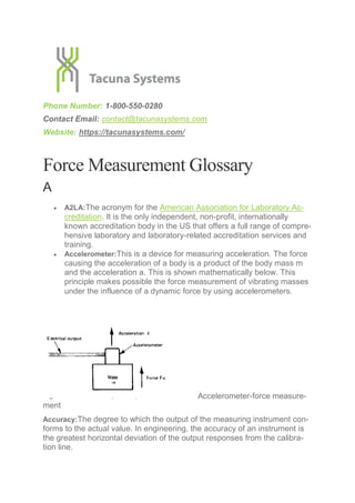
  • 1. Phone Number: 1-800-550-0280 Contact Email: contact@tacunasystems.com Website: https://tacunasystems.com/ Force Measurement Glossary A  A2LA:The acronym for the American Association for Laboratory Ac- creditation. It is the only independent, non-profit, internationally known accreditation body in the US that offers a full range of compre- hensive laboratory and laboratory-related accreditation services and training.  Accelerometer:This is a device for measuring acceleration. The force causing the acceleration of a body is a product of the body mass m and the acceleration a. This is shown mathematically below. This principle makes possible the force measurement of vibrating masses under the influence of a dynamic force by using accelerometers. Accelerometer-force measure- ment Accuracy:The degree to which the output of the measuring instrument con- forms to the actual value. In engineering, the accuracy of an instrument is the greatest horizontal deviation of the output responses from the calibra- tion line.
  • 2. Active Transducers:A transducer whose output power is supplied mostly by an external source of energy such as electrical energy. A good example of this is the strain gauge incorporated in a Wheatstone bridge to cause a voltage output due to changes in its resistance, the voltage output depends on the excitation voltage. Air Supply Regulator: The opening on a pneumatic load cell that regulates the supply of air into the confined space of the load cell’s cylinder. It is lo- cated close to the bottom of the load cell, below the diaphragm and con- trolled by a valve. Alloys: An alloy is a metal made from the combination of two or more met- als to give better or the desired properties. Such properties might include greater strength, greater resistance to corrosion, thermoelectric properties etc. They form a majority of the raw materials from which force measure- ment instruments are made. They include Nickel alloys, aluminum alloys, zinc-based alloys, copper alloys etc. Ambient Conditions: These are the weather or atmospheric conditions of the environment in which measurements are performed. They include tem- perature, humidity, and air pressure Amplifier: The electronic device that amplifies the magnitude of the electri- cal output of a transducer. Most transducers produce output electrical sig- nals that are very small in magnitude usually in the order of millivolts. This small signal cannot be used directly for processes such as system control or even display, hence an amplifier is used to boost the signal. The most commonly used and efficient amplifier for force measurement is the Instru- mentation Amplifier. Analog Circuit: An electronic circuit that deals or handles continuously vary- ing signal called analog signals for the purpose of conveying information through changes in current, voltage or frequency. Old instruments relied on this type of circuit, but in modern instruments, they are used in combination with digital circuits to give a more accurate result. Analog Instrument: The category of measurement instruments that consists basically of an input transducer, signal conditioners that amplify and filter the signal and output elements such as displays. The input transducer con- verts the analog signal into an equivalent analog electrical signal that has to be amplified, with electrical noise filtered off and then displayed to indi- cate the quantity of the analog signal.
  • 3. Analog-Digital-Converter: An electronic systems that convert the analog out- put of force transducers into digital signals. It is abbreviated as ADC and consists of elements such as anti-aliasing filter circuits, sample and hold circuits, and digital encoders. There are also different types such as the flash ADC, successive approximation ADC, and sigma-delta ADC. Angular Load Concentric: The load applied in a way that its central axis is concentric with the primary axis of the load application point but at an angle with respect to the primary axis. Angular Load Eccentric: The load applied in a way that its central axis is ec- centric with the primary axis of the application point and at an angle with re- spect to the primary axis. ANSI: The acronym for the American National Standards Institute. It is a non-profit private organization that oversees the development of voluntary consensus standards for products, services, processes, systems, and per- sonnel in the US. Some of these standards apply to force measuring instru- ment such as load cells. Anti-Aliasing Filter: The electronic circuit that bandlimits the output of a transducer to frequencies below the Nyquist frequency. This is so that ali- asing would not occur when the signal is being converted back to its analog form by a DAC. This is present in modern digital instruments. Application Point: The point of application of the load/force or weight to be measured by the instrument. It normally should have a loading platform fixed to it so that the load is equally distributed and transmitted to the force measurement transducer. Automation: The creation and application of technology to monitor and con- trol the production and delivery of products and services. This is one of the vast applications of a force measuring instrument. Axial Alignment: The alignment of the applied force or load along the trans- ducer’s principal axis. This is very important in the design and installation of an accurate force measurement system. A good force measurement sys- tem that measures a single force component should be insensitive to or- thogonal force components. Axial Direction: The direction parallel to the axis of a body Axial Load: The load that acts parallel to the axis of the platform or point of application.
  • 4. Axial Load Axial Thrust: A propelling force that is applied along the axis of a body in or- der to push the body against a platform towards an opposite direction. It is the type of driving force generated by the propulsion system of an airplane and a pogo stick. B  Bonded Resistive Foil: A thin piece of a metal strip attached to a struc- tural member of an instrument or bonded to a non-conductive back- ing. This describes a strain gauge.  Bleed Valve: A valve attached to the body of the diaphragm of a pneu- matic load cell. Its movement with respect to the deflection of the dia- phragm by the external load closes and opens the outlet nozzle of a pneumatic load cell.  Bourdon Tube: The tube that connects the outlet of a pressure trans- ducer to the pressure gauge. It transmits the pressure (force) in the hydraulic load cell to the gauge.  Bulk Micromachining: The MEM fabrication technique which describes a subtractive process that uses etching to create large grooves, pits, and channels on a substrate. Bulk micromachining is majorly used in producing pressure sensors and accelerometers. C
  • 5.  Calibration: Calibration is the comparison of the reading of the force measurement instrument to a known standard and the maintenance of the evidentiary chain from that standard. It is also called traceabil- ity and it plays a great role in eliminating the systematic error.  Calibration Curve: A graph showing how the analytical response of the instrument changes with the applied force or load. There are sev- eral methods used in plotting this curve, one of which is finding the straight line that best fits the scattered set of readings.  Calibration Weights: The sets of known weights used when calibrating a weighing instrument so as to ensure the accuracy of future results. The weight sets consists of different sizes, with the output for each applied weight forming a part of the reading to be plotted as a calibra- tion curve. Check Out: Calibration Weights at Tacuna Systems  Capacitive Load Cell: A load cell that causes the capacitance of the transducer to vary with the stimulus. The changes in capacitance are converted into electrically measurable quantities such as voltage, which then shows the equivalent size of the force or load being measured. This type of load cell demands electronic circuitry but its design is mechanically simple and also very sensitive to the input sig- nal.  CE: The abbreviation of the French phrase “Conformité Eu- ropéene“ which means “European Conformity” in English. This mark- ing shows that an instrument complies with the requirements of the European health, safety, and environmental protection legislation.  Load Cell Indicators: The devices that provide high accuracy output and allow easy amplification and display of the measured load (force/weight). They include LCD and LED displays for easy reading of measurements.  Center Of Mass: The unique location on the body at which the total mass of this body acts. The total mass of a body is assumed to be fully concentrated at its center of mass.  Centrifugal Force: The type of force that acts on a body that is in a cir- cular motion. The force is directed away from the center of rotation of the body.  Certificate of Conformity: A document given by a competent authority to original equipment manufacturers showing that their equipment, products or services meet the required specifications. These specifi- cations include a set of regulatory, technical and safety requirements.  CMRR: The acronym for Common mode rejection ratio of an opera- tional amplifier. It is the ratio of the differential gain to the common mode gain. Simply put, it describes the ability of the operational am- plifier to maximize the differential gain at the expense of the common mode gain. It is normally quoted in dB.
  • 6.  Common Mode Signals: These are identical signal components on the inverting and non-inverting inputs of an instrumentation amplifier. Common mode signals are noise signals that are induced equally in both input terminals, the input wires are always closely twisted to- gether to help reduce the noise effects. This, therefore, means that an ideal instrumentation amplifier will cancel out the common mode signals and amplify only the differential signals between the two wires.  Compression Force: The physical force that acts inward on a body and causes it to become compacted. This type of force is observed when a spring is compressed and the physical dimensions and geo- metric shape of the spring changes.  Corrugated Plate Diaphragms: These are diaphragms that have greater deflections, better linear characteristic curve, and improved sensitivity when compared to flat diaphragms. They are majorly used in high-pressure applications especially in pneumatic load cells.  Creep: This depicts the change in the load cell output with time when a constant load is placed on its point of application and all the ambi- ent conditions are kept constant. This means that if a known constant weight is placed on the load cell for a long time, the output reading changes over time even though no weight is being added or re- moved. The creep for a particular load cell is always specified in its datasheet.  Creep Recovery: This is the change of output following a step de- crease in the applied force, usually from the rated load capacity to zero-load. In other words, it is the change in the zero-load output of a load cell after the removal of the rated load that has been applied for a specific period of time. It is specified as a percentage of the rated load capacity over a specific period of time. D  Data Acquisition: This is the process of measuring physical stimulus (in this context, force, load or weight), converting the result into digital signals and storing them in computer memory for later use or distri- bution. Modern instruments are basically data acquisition systems whose output can be stored in a computer or even transmitted over a long distance remotely.
  • 7. Data Acquisition  Data Acquisition Rate: This is another name for Sampling rate.  Data Filtering: The removal of unwanted noise signals from the data being acquired so as to obtain an accurate reading.  Datasheet: The document that shows the summary of the technical and performance characteristics of an instrument. The details con- tained in this document is very useful to engineers when designing a system that requires the incorporation of the instrument. It is always provided by the supplier or the OEM.  Dead Load: The constant load in a structure due to the weight of its structural members or accessories.  Deformation: A change is the dimensions (length and area) of a mate- rial when subjected to a stress or strain.  Deflection: The change in the length of a structural member of a load cell when subjected to a load. In a force-balance measuring instru- ment, the load causes a deflection in the diaphragm and transmits the applied load to the fluid or gas in the confined space. In a strain gauge load cell, the deflection of the structural members transmits the applied load by causing a strain to the strain gauge.  Diaphragm: These are thin elastic plates that deform when subjected to loading.  Dielectric: The electrical insulator located between the two parallel metallic plates of a capacitive transducer.  Digital Instrument: The category of a measurement instrument that deals with digital signals. It consists of the major elements present in an analog instrument. However, it requires majorly that the analog output from the input transducer be digitized by using an analog to digital converter. The digital signal is then processed by using a digi- tal signal processor to perform tasks such as filtering, multiplexing, digital display etc. The instrument can also include a digital to analog converter that generates an analog output equivalent to the original output. Generally, modern-day instruments are digital.  Digital Pressure Transducers: The pressure transducer whose output is in form of a digital signal. Most pressure transducers use pressure
  • 8. gauges to indicate the equivalent form of the quantity being meas- ured. Digital types have digital displays and the output can be trans- mitted over a long distance for remote monitoring of plants.  Digital-Analog Converters: These are electronic circuits that converts digital signals into analog signals. It is abbreviated as DAC. They work in an opposite manner in comparison to ADCs. The most com- mon types of DACs are the binary-weighted DAC and the R-2R lad- der DAC.  Drift: The random change in the output reading under constant load- ing conditions. It is kind of similar to creep.  Ductility: The ability of a metallic material to undergo plastic defor- mation when subjected to stress. Plastic deformation is often used as a technique to permanently record an applied force.  Dummy Gauge: The passive temperature compensation resistor placed on the arm adjacent to the active arm of a quarter-bridge strain gauge setup. The dummy gauge eliminates the effects of tem- perature on the strain measurement. This is because there are identi- cal temperature changes in both the active strain gauge and the dummy gauge.  Dynamic Force: The type of force whose magnitude varies with time. In measuring any instantaneous value, the force measurement instru- ment must have a frequency response sufficient enough to follow the changing force. E  Eccentric Loading: A loading condition in which the center of mass of the applied load is not on the central or neutral axis of the load cell’s application point. It is also called offset loading and it produces a bending moment along with the axial stress generated by the eccen- tric load.
  • 9. The Eccentric Loading  Eccentricity: The distance between the central axis of a transducer central axis to the center of mass of the load.  Elasticity: The ability of a material to undergo deformation under the influence of a force (compressive or tensile) without losing its original shape and size after the force is removed. This is true so far the ma- terial is not stretched or deformed beyond its elastic limit. The elastic limit once exceeded causes the elastic material to suffer permanent deformation  Electrical Excitation: The external electrical energy supplied to the in- put terminals of the transducer to power its operations.  Electrical Output: The electrical signal produced as the output of the transducer in response to the applied load.  Electrical Transducer: The sensor device that detects an external phe- nomenon or stimulus (such as force, pressure, displacement, accel- eration etc.) and transforms this into an equivalent analog electrical signal. The output electrical signal is therefore proportional to the ap- plied load, hence its value is quantified.  Electrostatic Sensitive Device: These are parts or components of a force measurement instrument that can be damaged by common electrostatic charges which build upon the instrument operators, tools and other types of conductors. It is abbreviated as ESD, which can also stand for electrostatic discharge.  EMC: The acronym for Electromagnetic compatibility. It is defined as the ability of an instrument or a device to function satisfactorily in its
  • 10. electromagnetic environment without introducing intolerable electro- magnetic disturbances to anything in that environment. In other words, for an instrument to be said to have an EMC, it must be able to operate efficiently without interfering with other systems within a specified electromagnetic environment.  EMI: The acronym for electromagnetic interference. This is a form of environmental pollution that can cause malfunctions of electrical and electronic devices, can prevent proper use of the radio frequency spectrum, can ignite flammable atmospheres and has a direct effect on the human tissue. EMC practices help to control various forms of EMI.  Environmental Conditions: The environmental factors that influence the operations of force measurement instruments. They are also called ambient conditions. They include the atmospheric pressure, ambient temperature, humidity etc.  Error: The difference between the actual value of a force, load or weight and the true value. In instrumentation, an error is always ex- pressed as a percentage of the full-scale output. Measurement errors are basically systematic errors and random errors.  ESD: The acronym for electrostatic discharge. It is the sudden flow of electricity between two materials at different potentials caused by the imbalance of electrons between the two. The acronym can also mean electrostatic sensitive device.  Etching: The process of removing parts of a thin film deposited on a substrate material. Etching is one of the steps involved in the produc- tion of MEMs such as strain gauges. There are different types of etching, but majorly they are dry and wet etching. F  Fatigue Life: The number of total full cycles of applied force which may be applied before the measurement uncertainty will be altered beyond specified limits.  Feedback Amplifiers:These are electronic devices used to amplify the output of a transducer employed in a feedback control system. The transducer measures the output of a process and then converts it into an electrical signal. The electrical signal, if weak, is amplified by a feedback amplifier and compared with the reference input or set point. Feedback amplifiers are instrumentation amplifiers.  Field Calibration Methods: These are methods used to determine the repeatability of the measurement process. These methods are very
  • 11. important in process application, where repeatability is far more criti- cal to the control system than the absolute accuracy of measure- ments.  Flapper: The other name for the bleed valve of a pneumatic load cell  Flexural Bond Strength: The flexural strength of a bonded material. It depicts the maximum amount of stress experienced by the bonded material at its moment of yield or fracture.  Foil Strain Gauge: A type of strain gauge that consists of a metal foil pattern mounted on an insulating backing or carrier. It is constructed by bonding a sheet of thin rolled metal foil on a backing sheet. The patterns on the gauge are produced by photo-etching.  Force Calibration: The process of calibrating a force measurement in- strument. It involves carrying out traceable measurements. Check out: Load Cell Calibration Service by Tacuna Systems  Force Measurement Methods:  Ductility: The techniques and principles employed in the design and of force measurement instruments. Some of the commonly employed methods are lever-balance methods, force-balance methods, pres- sure measurement, acceleration measurement and the use of elastic elements. You may find helpful: Force and Weight Measurement Re- sources You Can Refer To  Force Transducer: The device that transforms an applied force into an equivalent electrical output signal  Force-Balance Systems: The measurement systems that employ the use of feedback systems to ensure that the output electrical signal is directly proportional to the applied force. These systems give high stability, high accuracy and are suitable for measurement of dynamic and static force.  Formal Calibration: The calibration process that is normally performed by approved laboratories, where the instrumentation used is periodi- cally calibrated and traceable to primary standards; the operators are well trained in calibration techniques, the temperature is controlled, and atmospheric pressure and humidity accurately measured.  Frequency Response: The highest sinusoidal frequency component of an applied force that the force measurement instrument can measure to a specified satisfactory accuracy.  Full-Bridge Strain Gauge Load Cell: The strain gauge load cell that has four strain gauges fixed into the four arms of a Wheatstone bridge cir- cuit. The strain gauges are arranged such that the two responding to either compression or tensile forces are on adjacent arms.
  • 12. Full-Bridge Strain Gauge Load Cell  Full-Scale Output: This is the output of the force measurement system at rated load capacity minus the output at zero-load. It is abbreviated as FSO and also called the span or rated output. G  Gauge Factor: The ratio of the fractional change in resistance to the fractional change in length. It is a very useful parameter for compar- ing the quality of strain gauge transducers. H  Half-Bridge Load Cell: The strain gauge load cell that has two strain gauges fixed into adjacent arms of a Wheatstone bridge circuit, to- gether with circuit completion resistors.  Hooke’s Law: The law states that the force needed to extend or com- press a string by some distance is proportional to that distance. This principle is applied in designing mechanical sensors that measure forces by transforming the force into the deformation of an elastic medium. Mathematically, the law is expressed as;  Hydraulic Fluid: The medium by which the pressure generated by the applied load is transmitted to the pressure gauge. The fluid is housed in the confined space in a hydraulic pressure transducer.  Hydraulic Load Cell: A type of mechanical, force-balance load cell de- vice that measures pressure or load by using a piston-cylinder ar- rangement. This arrangement uses a fluid housed in a confined space in the body of the cylinder to transmit pressure to a pressure gauge through a connecting tube. The pressure output on the gauge then shows the equivalent size of the applied load. The pressure out- put can also be a pressure transducer instead of a gauge.
  • 13.  Hysteresis: The difference of output readings between the increasing and decreasing forces at any given force. That is, it is the difference between the readings of a load cell transducer as the load is in- creased [from zero-load to its rated capacity] and the readings as the load is decreased [from rated capacity to zero-load]. I  IAQG: The acronym for the International Aerospace Quality Group. It is an organization that focuses on the continuous improvement of the processes within the supply chain to deliver consistently high-quality products. A part of its objectives is to establish common quality standards and requirements. These standards apply to various force measurement instruments  IEC: The acronym for the International Electro-Technical Commis- sion. It is an international standards organization that prepare and publishes international standards that prepares and publishes inter- national standards for all electrical, electronic and related technolo- gies  Input Terminal Resistance: The resistance measured across the exci- tation terminals of a force transducer at standard test conditions, with zero-load, and with the output terminals open circuited.  Insulation Resistance Tests: The test carried out when there are un- stable readings and random changes in the zero balance point of the load cell. It is done by connecting all the conductors together and then the resistance between all the connected wires and the load cell body is measured  ISA: The acronym for The International Society of Automation. It is a non-profit technical society for engineers, technicians, businesspeo- ple, educators, and students, who work, study or are interested in in- dustrial automation and pursuits related to it, such as instrumenta- tion.  ISO: The acronym for the International Organization for Standardiza- tion. It is a global network of the world’s leading standardizers that brings together experts from all over the world to develop Interna- tional Standards. The organization issues the certificate of conformity to OEMs. L  LCD: The acronym for Liquid Crystal Display.  LED: The acronym for Light Emitting Diode.
  • 14.  Load: This refers to forces, deformations, and weights exerted, ap- plied or placed on a surface. A load is a vector quantity, meaning it has magnitude and acts in a specific direction.  Load Cell: The sensor device that is used to detect a physical param- eter or stimulus (force and pressure) and then produce an output that is proportional to the stimulus. Load cells are generally linear sys- tems but they are of different types and designs with the most com- mon ones being hydraulic load cell, strain gauge load cell and pneu- matic load cell. Read: How Do Load Cells Work?  Load Cell Accessories: The materials that supplement load cells and they include load cell cables and connectors, lifting, crane or tension eye bolts, mounting kits and spacers for proper installation and sup- port of load cells. Check Out: Load Cell Accessories at Tacuna Sys- tems  Load Cell Materials: The raw materials from which load cell devices and their parts are fabricated. These materials include stainless steel, hydraulic oil, phosphor bronze, beryllium bronze, plastics, glass, basic metals, copper-nickel, nickel-chromium, platinum-tungsten al- loy. The materials are always chosen based on desired properties such as strength, weight, malleability, corrosion resistance, thermal conductivity, electrical conductivity, machining, viscosity, volatility, thermal expansion etc. Read: An Important Guide to Load Cell Materi- als  Loading Platform: The interface through which force/load is applied to a force transducer. Depending on the design, there may be upper and lower loading surfaces of a compression force transducer or the upper and lower screw threads of a tension device. Load cells should come with mounting kits that serve as loading platforms and ensure appropriate force distribution on the device.  LVDT: The acronym for Linear Voltage Differential Transformer. It is an inductive transducer that consists of a primary winding and two secondary windings wound around a magnetic core. The primary winding is excited by an AC voltage, the movement of the magnetic core then varies the mutual inductance of the two secondary wind- ings with respect to the primary coil. The device uses the basic princi- ples of magnetics to detect a load and then produce an output volt- age proportional to the load. M  Machine Operator: The skilled personnel that has been trained to op- erate a machine or device such as a force measurement instrument.
  • 15.  Magneto-Elastic Load Cell: The force transducer that operates on the effect that when a ferromagnetic material is subjected to mechanical stress, the magnetic properties of the material are altered and the change is proportional to the applied stress. They are majorly used in rough and electrically disturbed environments.  Manometer: The device that measures the pressure in a liquid. It is commonly used in conventional hydraulic load cells.  Mechanical Vibrations: These are oscillations that repeat within a time period. There are different classes of vibration: free (undisturbed) and forced (disturbed), damped and un-damped (has negligible or no damping), nonlinear and linear, and random (unpredictable) and de- terministic.  MEMS: The acronym for Micro-Electro-Mechanical-Systems. They are miniaturized electro-mechanical elements that are made using micro- fabrication techniques.  Micromachining: This refers to techniques for fabrication of 3D struc- tures on the micrometer scale. It is a new trend in manufacturing that seeks to meet the demands for micro components for reduced size and weight applications. MEMs are manufactured using microm- achining techniques such as photolithography, laser micromachining, micro-electronic discharge machining etc.  Microcontrollers: : A small computer unit on a single integrated circuit. The computer system consists of a processor, memory and other pe- ripherals. They are embedded in the design of modern force meas- urement instrument for the purpose of performing digital signal pro- cessing. The microcontrollers have analog to digital input terminals and digital output terminals that can connect to actuators and display devices to control an industrial process or display the result of meas- urements.  Modulus Of Elasticity: The measure of the resistance of a material to elastic deformation when subjected to a load.  mV: : This means Milli-Volt. The raw unconditioned analog output of an electrical transducer is always a weak signal of the order of milli- volts. N  Natural Frequency: The rate at which a body vibrates when it is not disturbed by an external force. In simple terms, when a body is given an initial displacement force and the force is withdrawn, the body starts oscillating about its initial equilibrium position and continues to oscillate on its own accord with any external force acting to keep it in motion.
  • 16.  Necking: This is a mode of tensile deformation where relatively large amounts of strain localize (permanently) disproportionately in a small region of the material. The neck constitutes a decrease in the local cross-sectional area and it can break when enough strain is applied across it.  NEPSI: The acronym for the National Supervision and Inspection Center for Explosion Protection and Safety of Instrumentation. It is a government approved establishment that is mainly engaged in re- search and development of explosion protection technology, testing, verification and certification of electrical equipment for use in explo- sive atmospheres, as well as explosion protection and safety supervi- sion and assessment of engineering projects.  Nominal Displacement: The measure of the deformation of the force transducer when the rated load is applied. It is a factor that deter- mines the stiffness of the transducer.  Nominal Force: The rated force or load that specifies the maximum capacity of the force transducer. It is the same thing as full-scale out- put. It is always specified in the instrument’s datasheet.  Nominal Temperature: The rated temperature range in which the force transducer works satisfactorily within the specifications in its datasheet.  Non-Linearity: Linearity: This describes the deviation of the true in- put/output curve from the idealized straight line approximating it. Ide- ally, the output of a force transducer is meant to be proportional to the applied load, however, in practical measurement, there exist dis- crepancies called non-linearity error.  NPL: The acronym for the National Physical Laboratory, UK’s national measurement institute.  NTEP: The acronym for the National Type Evaluation Program. O  OEM: The acronym for Original Equipment Manufacturer. This is a company that produces equipment and instruments such as a force measurement device that may be marketed by another manufacturer.  OIML: The acronym for the International Organization of Legal Metrol- ogy  OLED: The acronym for Organic Light Emitting Diode  Operating Range Of The Excitation Voltage: The range of temperature values within which a transducer can operate at its rated capacity and perform satisfactorily within its specifications.  Operating Temperature Range: This is the same as the Nominal or rated temperature range.
  • 17.  Output Resistance: The resistance measured on the output terminals of a transducer at a standard temperature at zero-load and zero exci- tation.  Overload Stop: The mechanical device designed to prevent overload- ing or overstressing of the transducer beyond its rated capacity. P  Piezoelectric Effect: This describes the ability of certain materials to generate an electric charge in response to an applied mechanical stress. Materials that exhibit this characteristic either occur naturally or artificially synthesized. Natural piezoelectric materials include Ber- linite, quartz, topaz and Rochelle salt, while artificial ones include Barium Titanate and lead Zirconate.  Piezoelectric Force Transducer: The transducer than uses the piezoe- lectric effect to measure an applied force or load. It is shown below. The applied force causes a proportional electrical charge to appear on the faces of the piezoelectric element. It is an active transducer, meaning the output power is supplied entirely by the input, hence a piezoelectric transducer does not need an external electrical excita- tion. Piezoelectric Force Transducer  Pneumatic Load Cell: A type of mechanical, force-balance load cell device that measures pressure or load by using a piston-cylinder ar- rangement. This arrangement uses a volume of gas housed in a con- fined space in the body of the cylinder to transmit pressure to a pneu- matic pressure dial gauge. The pressure output on the gauge then shows the equivalent size of the applied load. The pressure output can also be a pressure transducer instead of a gauge.
  • 18.  Precision: This describes the reproducibility of the measurement sys- tem.  Pressure Transducer: The device that senses physical pressure and transforms it into an equivalent output signal, usually in an electrical form. The pressure transducer can replace the pressure gauge pre- sent at the pressure output of a pneumatic or hydraulic load cell. It of- fers more accurate readings than a pressure gauge.  Primary Axis: The axis along which the applied load or face is de- signed to act. It is situated around the point of application of the force measurement instrument. Q  Quarter-Bridge Load Cell: The load cell type that has a single strain gauge fixed into an arm of a Wheatstone bridge circuit together with completion resistors and a dummy gauge for temperature compensa- tion. R  Random Errors: The errors that depict variations in output readings, that even though clearly observed, are difficult to explain. In engi- neering, probability and statistical tools are used in estimating ran- dom error. It is assumed that the random signal or error belongs to an ensemble of signals, with each signal having its own probability of occurrence. The probability distribution of the error is uniform about the mean.  Rated Capacity: This is the full-scale output.  Recalibration: The process of performing calibration after the initial calibration is done. Frequent recalibration should be performed at regular intervals of about 1 year to ensure that the instrument pro- vides accurate measurements.  Reference Standard: A force measurement instrument whose perfor- mance characteristics are known in relation to a primary standard.  Reliability: The probability of the instrument performing satisfactorily under the stated conditions for a specified period of time.  Repeatability: The measure of the agreement between the results of successive measurements of the differences of the output of a force measurement system for repeated applications of a given force in the same direction and within the range of the calibration forces applied. It shows the ability of a force measurement system to measure force consistently.
  • 19.  Reproducibility: The closeness of the agreement between the results of the measurements of the same force carried out under changed conditions of measurement  Resistivity: The electrical resistivity is the property of a material to re- sist the flow of electric current through. Mathematically, it is ex- pressed as Resistivity  Resolution: The ability of the force measurement system to detect and reliably indicate small changes in the characteristic of the meas- urement result.  ROHS: The acronym for the Restriction of Hazardous Substances.  RS232: The acronym for the Recommended Standard 232, a stand- ard communication protocol for networking a computer and periph- eral devices (such as a digital measurement instrument) to allow se- rial data exchange. S  Safe Over Range: The maximum load that can be applied to a force transducer without causing plastic deformation to its elastic element.  Semiconductor Gauge: A strain gauge type manufactured from strips of semi-conducting silicon in either n-type or p-type. It exhibits special characteristics such as high output, no creep, and hysteresis, long fa- tigue life. They are widely used in force transducers, accelerometers, and pressure sensors.  Sensitivity: The rate of change of the output signal as the desired sig- nal at the input varies. The sensitivity of a transducer allows us to predict the output voltage from the knowledge of the excitation volt- age and the value of the applied stimulus.
  • 20.  Shear Force: The force that acts perpendicular to the longitudinal axis of the body. It tends to divide the body along a plane parallel to an opposing stress  Shielding: This involves placing a conductive surface around the criti- cal parts of the instrument’s circuit so that the electromagnetic field which couples to it is attenuated. A good force transducer has a shield wire as its fifth wire terminal.  Shock Resistance Test: The test carried out when there are unstable readings and random changes in the zero balance point of the load cell. It is done by connecting all the conductors together and then the resistance between all the connected wires and the load cell body is measured.  Shunt Calibration: The calibration of a load cell transducer by the in- sertion of known shunt resistors into the appropriate arms of its Wheatstone bridge circuit.  Shunt-To-Load Correlation: The numerical difference between the out- put readings obtained from shunt calibrations and the actual applica- tion of loads.  Signal Conditioning Circuit: The circuit that performs signal filtering, amplification, and isolation to ensure a more accurate result is ob- tained.  Stabilization Period: The time interval required to ensure that any fur- ther changes in the load to being measured is tolerable. Simply put, it is the time required for the output readings to stabilize and maintain a certain value before it is recorded as the actual output value.  Standard Test Conditions: The ambient conditions under which meas- urements should be performed. It is abbreviated as STC. The condi- tions will include factors such as temperature, humidity, and pressure for force measurements.  Static load: A load whose size/magnitude does not change with time.  Stiffness: The ability of a body to resist deformation when a load is applied to it. It is similar to the young modulus.  Strain: The fractional change in dimension (length). It is the ratio of the change in length to the instantaneous or original length. It is also called the Engineering Strain  Strain Gauge: A resistive element that produces a change in its re- sistance proportional to an applied mechanical strain.  Strain Gauge Transducers: The transducer type that uses the strain gauge as its underlying mechanism. It has the strain gauge(s) at- tached to a structural, which undergoes deformation when a load is applied to the load cell. It is the most common type of load cell found in measurement devices all across various industries.
  • 21.  Stress: The ratio of the force applied to the cross-sectional. When- ever a material is loaded, a stress is generated within it that causes a deformation in its geometric shape.  Structural Member: The constituent part of force transducers that pro- vides support and housing for other components. The geometric shape of the structural member also determines the category to which the load cell belongs. According to the shape of the structural members, load cells can be beam load cells, disk load cells, S- type, tension link load cell and miniature load cell.  Summing Junctions: There are used for summing data output from multiple load cells into a single output.  System Requirements: The necessary and desired specifications and standards that the force measurement system must meet. It is always specified by the user, client or the expert designing the whole sys- tem. When the system requirements are known, then the specific in- strument that best matches these requirements are selected for use.  Systematic Error: This is the error inherent in the operation of a force measurement instrument. It can be eliminated through system cali- bration. T  Tare Weight: The weight of an empty container or the loading plat- form.  TEDS: The acronym for the Transducer Electronic Datasheet. It con- tains details about the technical and performance characteristics of the transducer.  Telemetry: An automated communication process that describes the transmission of data or information between two geographical loca- tions. In instrumentation, transmission is required to enable central- ized supervisory data login, signal processing or control of large- scale systems. Telemetry can be provided by electrical transmission as well as pneumatic transmission. Pneumatic transmission is em- ployed in a hazardous area where an electrical power failure can be very disastrous.  Temperature Compensation: This is carried out to eliminate the dimen- sional changes caused by temperature changes in a transducer. To cater to these unwanted thermal effects, self-temperature compen- sated gauges are used. Dummy gauges can also be used so that the thermal effects will cancel and be eliminated from the output.  Tensile Force: The force that stretches or elongates the size of a ma- terial
  • 22.  Tensile Strength: The capacity of a material to withstand tensile forces wanting to stretch the material.  Thin Film Strain Gauge: The strain gauge type produced by evaporat- ing thin films of metals or alloys onto an elastic element.  Tolerance: The allowable maximum deviation from the standard spec- ifications.  Torque: The turning effect caused by a force acting at a distance on a body. It is the product of the force and the perpendicular distance be- tween the line of action of the force and the center of rotation at which it is exerted.  Torsional Modulus: The modulus of elasticity of a material when sub- jected to a torque force.  Traceability: This is another name for Calibration.  Troubleshooting: The process of detecting, tracking, analyzing and correcting faults in a measurement system. There are various standard troubleshooting procedures to follow for each force meas- urement instrument.  True Strain: This is the natural logarithm of the Engineering Strain. U  Ultimate Elongation: This is the maximum elongation suffered by a material at rupture when subjected to tensile forces  Ultimate Strength: The maximum stress a material can withstand be- fore it breaks.  Unloaded Output Voltage: The electrical output voltage from the force transducer under zero load or no load. V  Vibrating Wire Load Cell: The transducer that consists of a taut ferro- magnetic wire that is excited into transverse vibrations by a drive coil. These vibrations are detected by a pick-up coil. The drive coil and pickup coil have magnetic cores and once the wire has been excited to its resonant frequency for a given tension. This frequency is main- tained by a self-oscillatory systems system formed between the two coils. The resonant frequency is, therefore, a measure of the applied force at that instant.  Visual Displays: These are used to indicate either qualitative or quan- titative events. A qualitative event means the presence or absence of some signals. A quantitative event means the value of the signal. LEDs and LCDs are the common types of visual displays.
  • 23. W  Wheatstone bridge: A circuit configuration that is majorly used to measure electrical parameters such as resistance, inductance, and capacitance. The configuration incorporates an excitations source, four arms where passive components can be fixed and an output ter- minal. It should be noted that In order to measure capacitance or in- ductance, the normal Wheatstone bridge is modified but still follows the same circuit configuration pattern.  Wire Strain Gauge: The original type of resistance strain gauge, though now widely replaced by foil and thin film strain gauges. It still finds application in high-temperature transducers and stress analysis. Y  Young Modulus: The ratio of the stress caused by an applied force acting over an area of a material to the strain. Z  Zero Balance: This is the default output signal of the transducer when no load or zero-load is applied to it.  Zero Offset: The difference between the zero-load specified in the in- strument’s datasheet and the actual zero load output obtained by di- rect measurement under zero-load conditions (removal of all weights, loads and dead load). Sources 1. Difference between Analog and Digital Circuits. 2. Definition of Analog Circuits 3. Instrumentation Systems 4. https://www.chegg.com/homework-help/definitions/mechanical-vibra- tions-5 5. Instrumentation Reference Book, W. Boyes. 6. A Guide to the Measurement of Force, Andy Hunt.
  • 24. Phone Number: 1-800-550-0280 Contact Email: contact@tacunasystems.com Website: https://tacunasystems.com/