Transforming Data Streams with Kafka Connect: An Introduction to Single Messa...
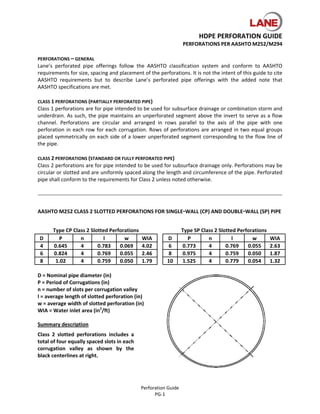
Hdpe perforation guide
1. HDPE PERFORATION GUIDE
PERFORATIONS PER AASHTO M252/M294
PERFORATIONS – GENERAL
Lane’s perforated pipe offerings follow the AASHTO classification system and conform to AASHTO
requirements for size, spacing and placement of the perforations. It is not the intent of this guide to cite
AASHTO requirements but to describe Lane’s perforated pipe offerings with the added note that
AASHTO specifications are met.
CLASS 1 PERFORATIONS (PARTIALLY PERFORATED PIPE)
Class 1 perforations are for pipe intended to be used for subsurface drainage or combination storm and
underdrain. As such, the pipe maintains an unperforated segment above the invert to serve as a flow
channel. Perforations are circular and arranged in rows parallel to the axis of the pipe with one
perforation in each row for each corrugation. Rows of perforations are arranged in two equal groups
placed symmetrically on each side of a lower unperforated segment corresponding to the flow line of
the pipe.
CLASS 2 PERFORATIONS (STANDARD OR FULLY PERFORATED PIPE)
Class 2 perforations are for pipe intended to be used for subsurface drainage only. Perforations may be
circular or slotted and are uniformly spaced along the length and circumference of the pipe. Perforated
pipe shall conform to the requirements for Class 2 unless noted otherwise.
AASHTO M252 CLASS 2 SLOTTED PERFORATIONS FOR SINGLE‐WALL (CP) AND DOUBLE‐WALL (SP) PIPE
Type CP Class 2 Slotted Perforations Type SP Class 2 Slotted Perforations
D P n l w WIA D P n l w WIA
4 0.645 4 0.783 0.069 4.02 6 0.773 4 0.769 0.055 2.63
6 0.824 4 0.769 0.055 2.46 8 0.975 4 0.759 0.050 1.87
8 1.02 4 0.759 0.050 1.79 10 1.525 4 0.779 0.054 1.32
D = Nominal pipe diameter (in)
P = Period of Corrugations (in)
n = number of slots per corrugation valley
l = average length of slotted perforation (in)
w = average width of slotted perforation (in)
WIA = Water inlet area (in2/ft)
Summary description
Class 2 slotted perforations includes a
total of four equally spaced slots in each
corrugation valley as shown by the
black centerlines at right.
Perforation Guide
PG‐1
2. HDPE PERFORATION GUIDE
PERFORATIONS PER AASHTO M252/M294
AASHTO M294 CLASS 2 SLOTTED PERFORATIONS FOR DOUBLE‐WALL (SP) PIPE
Type SP Class 2 Perforations
D d L WIA
12 0.3125 1.94 2.85
15 0.3125 2.62 2.11
18 0.3125 2.96 1.87
D = Nominal pipe diameter (in)
d = diameter of circular perforation (in)
L = Longitudinal spacing between holes (in)
WIA = Water inlet area (in2/ft)
Summary description
Class 2 perforations for 12", 15" and 18"
HDPE pipes include a total of six equally
spaced 5/16" diameter holes in each
corrugation valley as shown at right.
Type SP Class 2 Perforations
D d L WIA
24 0.3750 3.95 2.68
30 0.3750 4.01 2.64
36 0.3750 4.06 2.61
42 0.3750 5.38 1.97
48 0.3750 5.37 1.97
D = Nominal pipe diameter (in)
d = diameter of circular perforation (in)
L = Longitudinal spacing between holes (in)
WIA = Water inlet area (in2/ft)
Summary description
Class 2 perforations for 24", 30", 36",
42" and 48" HDPE pipes include a total
of eight equally spaced 3/8" diameter
holes in each corrugation valley as
shown at right.
Perforation Guide
PG‐2
3. HDPE PERFORATION GUIDE
PERFORATIONS PER AASHTO M252/M294
AASHTO M252 CLASS 1 PERFORATIONS FOR DOUBLE‐WALL (SP) PIPE
AASHTO M252 Type SP Class 1 Perforations (6" through 10")
D 1 2 L Lmin H Hmax s1/2 d S WIA
6 48 70 4.46 3.74 1.97 2.76 1.15 0.1875 0.75 1.77
8 48 70 5.95 5.12 2.63 3.70 1.54 0.1875 1.00 1.33
10 48 70 7.43 6.30 3.29 4.72 1.92 0.3125 1.75 2.10
D = Nominal diameter (in)
1 ≥ 37.5°, 2 ≤ 85° (AASHTO maximum and minimum angles)
s = arc length between holes (in)
d = diameter of circular perforation (in)
S = longitudinal spacing between perforations (in)
WIA = Water inlet area (in2/ft)
Summary description
Class 1 perforations for 6", 8" and 10" HDPE pipes include a total of four
holes in each corrugation valley as shown below. Perforations for the 6"
and 8" pipes shall be 3/16" diameter, while the perforations for the 10"
pipe shall be 5/16" diameter.
Perforation Guide
PG‐3
4. HDPE PERFORATION GUIDE
PERFORATIONS PER AASHTO M252/M294
AASHTO M294 CLASS 1 PERFORATIONS FOR DOUBLE‐WALL (SP) PIPE
AASHTO M294 Type SP Class 1 Perforations (12" through 18")
D 1 2 3 L Lmin H Hmax s1/2 s2/3 d S WIA
12 47 62 78 8.78 7.56 4.75 5.43 1.57 1.68 0.38 1.94 4.10
15 47 62 78 10.97 9.45 5.94 6.77 1.96 2.09 0.38 2.62 3.04
18 47 62 78 13.16 11.34 7.13 8.15 2.36 2.51 0.38 2.96 2.69
D = Nominal diameter (in)
1 ≥ 40°, 3 ≤ 85° (AASHTO maximum and minimum angles)
s = arc length between holes (in), must be ≥ 1 inch
d = diameter of circular perforation (in)
S = longitudinal spacing between perforations (in)
WIA = Water inlet area (in2/ft)
Summary description
Class 1 perforations for 12 through 18‐in HDPE pipes include a total of six
⅜" diameter holes in each corrugation valley as shown below.
Perforation Guide
PG‐4
5. HDPE PERFORATION GUIDE
PERFORATIONS PER AASHTO M252/M294
AASHTO M294 CLASS 1 PERFORATIONS FOR DOUBLE‐WALL (SP) PIPE
AASHTO M294 Type SP Class 1 Perforations (24" through 48")
D 1 2 3 4 L Lmin H Hmax s1/2 s2/3 s3/4 d S WIA
24 46 57 68 79 17.26 15.36 9.71 11.04 2.30 2.30 2.30 0.375 3.95 2.68
30 46 57 68 79 21.58 19.20 12.14 13.80 2.88 2.88 2.88 0.375 4.01 2.64
36 46 57 68 79 25.90 23.04 14.57 16.56 3.46 3.46 3.46 0.375 4.06 2.61
42 46 57 68 79 30.21 26.88 16.99 19.32 4.03 4.03 4.03 0.375 5.38 1.97
48 46 57 68 79 34.53 30.72 19.42 22.08 4.61 4.61 4.61 0.375 5.37 1.97
Summary description
Class 1 perforations for 24 through 48‐in HDPE pipes include a total of
eight ⅜" diameter holes in each corrugation valley as shown below.
D = Nominal diameter (in)
1 ≥ 40°, 4 ≤ 85° (AASHTO maximum and minimum angles)
s = arc length between holes (in), must be ≥ 1 inch
d = diameter of circular perforation (in)
S = longitudinal spacing between perforations (in)
WIA = Water inlet area (in2/ft)
Perforation Guide
PG‐5