FULL NIGHT — 9999894380 Call Girls In Mahipalpur | Delhi
Bit mech fyp report_high performing
1. NOVEL STUDY ON MECHANICAL BEHAVIOUR OF
NATURAL FIBRES REINFORCED 3D-PRINTED
PETG-BASED COMPOSITE MATERIAL
PROJECT REPORT
Submitted by
GOKUL R (161ME138)
GURUPRAKASH T (161ME151)
NANDHA KUMAR P (161ME204)
in partial fulfilment for the award of the degree
of
BACHELOR OF ENGINEERING
in
MECHANICAL ENGINEERING
BANNARI AMMAN INSTITUTE OFTECHNOLOGY
(An Autonomous Institution Affiliated to Anna University, Chennai
SATHYAMANGALAM-638401
ANNA UNIVERSITY: CHENNAI 600 025
AUGUST 2020
2. ii
BONAFIDE CERTIFICATE
Certified that this project report “NOVEL STUDY ON MECHANICAL
BEHAVIOUR OF NATURAL FIBRES REINFORCED 3D-PRINTED
PETG-BAED COMPOSITE MATERIAL” is the Bonafide work of
GOKUL. R (161ME138), GURUPRAKASH. T (161ME151) and
NANDHA KUMAR. P (161ME204) who carried out the project work under
my supervision.
SIGNATURE
Dr. Ravikumar. M
HEAD OF THE DEPARTMENT
Professor & Head
Department of Mechanical Engineering
Bannari Amman Institute of Technology
Sathyamangalam
Erode - 638 401
SIGNATURE
Dr. Ramesh Kumar. T
SUPERVISOR
Associate Professor
Department of Mechanical Engineering
Bannari Amman Institute of Technology
Sathyamangalam
Erode - 638 401
Submitted for project Viva Vice examination held on ……………
Internal Examiner External Examiner
3. iii
DECLARATION
We affirm that the project work titled “NOVEL STUDY ON
MECHANICAL BEHAVIOUR OF NATURAL FIBRES REINFORCED
3D-PRINTED PETG-BASED COMPOSITE MATERIAL” being submitted
in partial fulfilment for the award of the degree of Bachelor of Engineering in
Mechanical Engineering is the record of original work done by us under the
guidance of Dr.T. Ramesh Kumar, Supervisor, Associate Professor, Department
of Mechanical Engineering. It has not formed a part of any other project work(s)
submitted for the award of any degree or diploma, either in this or any other
University.
I certify that the declaration made above by the candidates is true.
SIGNATURE
Dr.T.Ramesh Kumar
Supervisor,
Associate Professor,
Department of Mechanical Engineering,
Bannari Amman Institute of Technology,
Erode - 638 401
GOKUL R GURUPRAKASH T NANDHA KUMAR P
(161ME138) (161ME151) (161ME204)
4. iv
ACKNOWLEDGEMENT
We would like to enunciate heartfelt thanks to our esteemed Chairman
Sri.S.V.Balasubramaniam, and the respected Director Dr.M.P.Vijaykumar,
for providing excellent facilities and support during the course of study in this
institute
We are grateful to Dr.M.Ravikumar, Professor and Head of the
Department, Mechanical Engineering, for his valuable suggestions to carry out
the project work successfully.
We wish to express our sincere thanks to Dr.G.Kumaresan, Associate
Professor and Professor in-charge, for his constructive ideas, inspirations,
encouragement and much needed technical support extended to complete our
project work.
We wish to express our sincere thanks to the Faculty guide
Dr.T.Ramesh Kumar, Associate Professor, Department of Mechanical
Engineering, for his constructive ideas, inspirations, encouragement, excellent
guidance and much needed technical support extended to complete our project
work.
We would like to thank our friends, faculty and non-teaching staff who
have directly and indirectly contributed to the success of this project.
Gokul.R (161ME138)
GuruPrakash.T(161ME151)
NandhaKumar.P (161ME204)
5. v
ABSTRACT
Polymer composites gave a breakthrough in new material discovery and
improved the functional usage of the materials in wide applications. Besides,
with new polymer composite discovery, there has a significant need in making it
more environmentally friendly which in the case can be done with addition
natural fibres to it. These fibres not only make polymer composites
environmentally friendly; they make the discovery more sustainable and
enhance the Mechanical properties when compared to their base properties.
This project work focused on how Polymer composite of Poly Ethylene
Terephthalate Glycol (PETG) with the addition of natural fibres (Sisal fibre and
Banana fibre) and test to various Mechanical tests such as Tensile test, Impact
test, Flexural test and Hardness test. Before the addition of fibres to the PETG
Polymer, fibres were treated with different chemical solutions (NaOH, KOH,
H2O2, NH4OH, CaCO3, Ba(OH)2) which in terms increases its overall strength
and enhance its Mechanical properties. Fibres have treated with different
chemical concentration (2%, 4%, and 6%) for various timings (30 min, 60 min,
and 90 min) and also tested for its B-Force value.
The best resulted fibres are chosen from the chemical treatment and the
specimens are fabricated by using 3D printing technique in which fibres are
layed in different lays of the specimen at an equal ratio. Three different printing
orientation (Zig-Zag, Tri-Hexagon and Cross 3D) of specimens are developed
and they are subjected to various Mechanical tests. The differences in
orientations are infill structure and time for printing and noted that the different
Mechanical test results are obtained according to the laying pattern. It is evident
that the test results of developed polymer composite showed improved strength
when compared to its base polymer composite.
Keywords: Sisal fibre, Banana fibre, PETG, 3D-Printing.
6. vi
TABLE OF CONTENTS
CHAPTER
Nos.
TITLE
PAGE
Nos.
ABSTRACT v
LIST OF FIGURES ix
LIST OF TABLES xii
1 INTRODUCTION 1
1.1 ADVANTAGES OF PETG 3
1.2 APPLICATIONS OF PETG 3
2 LITERATURE SURVEY 4
3 OBJECTIVES AND METHODOLOGY 10
3.1 OBJECTIVES 10
3.2 METHODOLOGY 11
4 EXPERIMENTAL PROCEDURE 12
4.1 FIBRE EXTRACTION PROCESS 13
4.2 CHEMICAL TREATMENT PROCESS 14
4.2.1 Treatment with KOH 15
4.2.2 Treatment with NaOH 16
4.2.3 Treatment with CaCO3 17
4.2.4 Treatment with Ba(OH)2 18
4.2.5 Treatment with NH4OH 20
4.2.6 Treatment with H2O2 21
4.3 SELECTION OF BEST FIBRE 22
4.4 SPECIMEN PREPARATION 24
4.5 MEHANICAL BEHAVIOUR OF
SPECIMEN
28
4.5.1 Tensile Test 28
4.5.2 Impact Test 30
7. vii
CHAPTER
Nos.
TITLE
PAGE
Nos.
4.5.3 Flexural Test 31
4.5.4 Hardness Test 33
4.6 BILL OF MATERIALS 34
5 RESULTS AND DISCUSSION 35
5.1 EXTRACTED FIBRE FROM PLANT 35
5.2 EFFECT ON CHEMICALLY TREATED
FIBRE
36
5.2.1 KOH Solution 36
5.2.2 NaOH Solution 37
5.2.3 CaCO3 Solution 38
5.2.4 Ba(OH)2 Solution 39
5.2.5 NH4OH Solution 40
5.2.6 H2O2 Solution 41
5.3 SELECTION OF HIGH STRENGTH FIBRE 42
5.3.1 Sisal Fibre 43
5.3.2 Banana Fibre 43
5.4 COMPOSITE PREPARATION 44
5.5 MECHANICAL RESULTS 44
5.5.1 Tensile Test 44
5.5.2 Impact Test 45
5.5.3 Flexural Test 46
5.5.4 Hardness Test 47
6 CONCLUSIONS 49
FUTURE SCOPES 50
REFERENCES 51
ANNEXURE I 52
INDIVIDUAL WORK CONTRIBUTION 52
13. 1
CHAPTER 1
INTRODUCTION
In recent decade, there has been a wide spread research carried out in new
Polymer based composites and thus Poly Ethylene Terephthalate Glycol
(PETG) has been the one in the new discovery. In comparison with various
Polymers available PETG tends to be more cost effective, high durability and
has positive chemical resistance. It can be easily formed into objects and they
withstand high pressure to negligence of crack formation. PETG is a sub
derivative of PET Polymer and possesses all good values of the PET Polymer
like formability to different shape and translucent properties. With relevance to
the printer used for printing, there will not be a greater variation in printing
quality and time as compared to other materials used such as Acrylonitrile
Butadiene Styrene (ABS), Poly Lactic Acid (PLA), Carbon fibres, etc. PETG is
purely an amorphous thermoplastic which has wide range of application in
injection moulding, extrusion, 3D printing, etc. Natural form of PETG is
colourless and semi crystalline.
PETG can even be processed into clear sheets which are widely used high
precision industries. PET is the formation of monomers together; with addition
of glycol it is PETG. Layer adhesion is very much good in PETG printing at
right printer settings and printing temperature. It is also cost effective and most
used in impact resistance applications with showing wonderful glazing
properties attached to it. Due to its surplus advantages it is used in wide range
product making especially in food industries for making of bottes and containers
as they are food safe too.
In addition to the base Polymer, natural fibres like Sisal and Banana are
added to enhance its various Mechanical properties. Based on wide range of
literature survey it was evident that Sisal fibre holds best strength of easily
14. 2
available fibres and they are cost effective too. In other hand Banana fibre holds
good result in elongation properties. Banana fibres are readily available and cost
effective. Both fibres can easily be extracted out and the wastage of fibre during
extraction is also minimal. With both the combination of fibre the best strength
to elongation result can be achieved when in use with the PETG material. With
increase in layer of these fibre addition the results are much better, subjected to
Mechanical tests.
The fibres are treated with chemical solutions to remove additives such as
lignin and other wax content present in it. The treatment included chemical
solution of salts such as NaOH, KOH, CaCO3, NH4OH, H2O2 and Ba(OH)2 of
different concentration. The fibres are even treated at different timings of
30 min, 60 min and 90 min to test the fibre behaviour. The fibres are treated
only in basic solution as acidic solution will etch the fibres. Even for higher
concentration and longer period of treatment will etch out the fibre. Chemical
treatment with basic improved the intermolecular forces between the fibres
which in hand improved its overall strength. The fibres are subjected to tensile
test to find out the best fibre in with the different chemical treatment at various
timings and concentration of chemical solution.
The best result show fibre has chosen among all to be integrated and
fabricated with PETG Polymer using 3D Printing technique. Before the printing
process began, machine parameters are accordingly set out like optimum
printing speed, temperature, printing pattern, fill ratio and printing speed to get
the best result. The fibres are accordingly laid out layer by layer in process of
specimen preparation. The specimen is prepared to their ASTM standards for
the Mechanical tests to be taken with variation in the laying pattern (Tri-
Hexagonal, Zig-Zag, Cross 3D). The fabricated specimen has taken for post
processing to remove additives present and improve surface finish.
15. 3
The specimen has subjected to Mechanical tests such as Flexural, Tensile,
Hardness and Impact test in order to study the specimen behaviour. The results
are noted down for each test for further study. It is to be noted that for every test
taken different lay pattern gave the best result. In accordance with the results,
application of usage can be decided out to further study. This result would also
give us an insight for preparation of new PETG composite and parameters for
printing can accordingly be altered to the need.
1.1 Advantages of PETG
1. PETG’s physical strength is generally greater than other polymers like
PLA. Along with natural fibres strength is further more improved.
2. Outdoor use of PETG in sunlight and weather are much better than others
even without painting.
3. PETG are completely biodegradable but it takes long time to break.
Along with natural fibres its degradability will not be affected.
4. Complicated structures can be easily made using PETG in3D-prining.
5. Temperature tolerance of PETG is good compared to other polymers.
6. Mimicking with other material is quite good in PETG.
7. Changing of filament in nozzle is easy.
1.2 Applications of PETG
1. Because of PETG’s combined strength and ductility it can be used as
many Mechanical component and robotic parts and use fibres along adds
even more strength.
2. Since PETG’s can bear high temperature it can be used in many areas in
automobile industry.
3. PETG is good chemical resistance with good water and other chemicals.
4. It is even used in many packaging industries and medical applications as
bottles, electronics, guards, etc.
16. 4
CHAPTER 2
LITERATURE SURVEY
Anoop Kumar Sood et al (2010) have discussed the parameters for
Mechanical property in FDM processed parts considering various parameters.
Layer thickness, machine orientation, angle of laying are some of the
parameters considered in this study. The prepared specimen was subjected to
different Mechanical tests such as Tensile, Flexural and Impact to widely
understand its behavior in varied models. The obtained values were plotted out
Selin et al (2003) have studied the PLA composite reinforced with flax fibres
subjected to various Mechanical tests. The fibres were added in different wt.%
(30% and 40%) to analyse its behaviour for Impact strength and it was clear that
for 50% fibre addition it showed reasonable improvement in results. Other than
fibres, Plasticizer was also added to study the effects but it did not show any
positive impact in the test taken. For Tensile test, addition of flax fibre showed
greater elongation as well Tensile strength of 600 MPa. SEM images were also
examined, which showed that fibres were not well integrated with the PLA
material. Degradation of PLA was not shown in GPC analysis as of its bonding
with flax fibres.
Behzad Rankouhi et al (2016) have analysed the 3D Printed ABS for
Mechanical and failure behaviour varying in its orientation and thickness of the
layers. Tensile test specimens were prepared according to ASTM standard and
were tested for their property. It was evident that 0.2 mm layer thickness
showed very good strength when compared to 0.4 mm. The breaking part was
keenly inspected via Electron Microscopy to understand the material
characteristic for different orientation. The obtained results were plotted in
ANOVA to get the best result out and decide the parameter which influence the
3D printing most and further study cab be carried out.
17. 5
in ANOVA to find the exclusive best result in each condition. With increase in
layer the gradient temperature was also high and it was greatly affected by its
orientation. Less raster angle resulted in more stress accumulation and poor
bonding of surface and no air gap is preferred.
Carmen R. Rocha et al (2014) have fabricated a binary and ternary polymer
of ABS blend via 3D printing and tested for its Mechanical Strength. With the
base ABS, SEBS & UHMWPE were blended to produce blended compound of
ME3DP. In addition of SEBS at 5% and 10% did not show much improvement
in Ultimate strength. Positive results were shown for every specimen in
consideration of stress-strain curve. SEM images were also examined to
understand how different blends propagated the crack formation.
Jaya Christiyan et al (2016) have experimented the study on ABS composite
for its process parameters in 3D printing and tested its Mechanical properties.
Hydrous Magnesium Silicate was the additive added as reinforcement to make
the composite. Printing speed and the layer thickness was greatly altered to
study the specimen behaviour. For both the Tensile and Flexural test taken,
Specimen printed with printing speed of 0.03 m/s and thickness of 0.0002 m
showed better results when all other specimen fabricated. This result greatly
shows that for lower printing speed and thickness the binding of layers and
density fill ratio was also good which resulted in positive result.
Cifuentes et al (2017) have assessed the PLA composites for its Mechanical
strength added with micro particles of Mg with help of depth indentation
analysis. The fabrication of composite was done by compression moulding with
Mg particles disintegrating with the raw PLA. During various tests taken it
clearly shows that with addition of nano particles of Mg at 5 wt.% gave great
improvement in its hardness value. Even DSI experiments proved good elastic
modulus for the specimen at UTS. Resistance to Plastic flow was positive with
addition of Mg particles to the base PLA material.
18. 6
Santhosh et al (2014) have studied the Coconut powder reinforced with
Banana fibre composite and subjected it to Mechanical tests to undermine its
results. Fibres were all treated with NaOH solution of concentration 5% to
increase its affinity of binding in the composite. The fibre weight fraction was
Jung Tae Lee et al (2010) have studied the denim fabric infused with PLA
and analysed its Mechanical behaviour for increasing layer of denim fabric. The
test specimen design was carried out on CAD software, with applying uniform
pressure on aside gave the result of elastic modulus. In consideration with layers
of denim fabric; fabric placed at three layers in PLA composite gave best result
for Tensile at 75.76 MPa, Tensile modulus at 4.65 GPa and Impact strength at
82 J. With above based results it could be well said that denim could a good
substitute in use other materials such as glass fibre and carbon fibre.
Xiaoyong Tian et al (2016) have understood the performance of PLA
composite with reinforcement of Carbon fibre and subjected it to various
Mechanical tests for better understanding about the Carbon fibre reinforcement
with PLA. With variation in printing speed, temperature and pressure, it is to be
observed that Temperature and Pressure played a vital role in all tests
undertaken. Microscopic analysis also revealed the good interfacial bonding
between Carbon fibre and PLA. At 27% fibre content in CFR-PLA gave best
result in Flexural test. This study further provokes the usage of CFR with
different Polymers to make light weight objects.
Hariprasad et al (2013) have studied the Coir-Banana hybrid composite
using FEM to understand its Mechanical behaviour. These fibres were treated
with Ether and Tetra Amine to improve its characteristics and were even
compared with raw fibres which are just from the stock. Epoxy was the binder
used in the fabrication followed up by hand lay technique in mould created.
Treated fibres showed positive traits when compared with untreated one in all
Mechanical tests (Flexural, Impact & Tensile) undertaken. The results were
even diagnosed with ANSYS and results proved the same.
19. 7
kept at constant about 30% throughout the specimen preparation of treated and
untreated one. Treated fibre showed grater improvement in Mechanical strength
(Flexural and Tensile) in comparison to the other variation. SEM images also
gave a clear-cut idea of how fibres were well integrated with the resin.
Dharmalingam et al (2018) have experimented the fabrication of Kenaf-Sisal
hybrid composite with treated and untreated combination and analysed its
Mechanical behaviour. Both fibres were taken in equal size of 0.33 m and equal
layer laying of 0.31 m. Fibres were treated with Sodium Hydroxide solution for
improving its affinity as well removing additives presented such as lignin.
Fibres of equal ratio were taken to fabrication using traditional technique with
the use epoxy resin. Treated fibre showed hardness value of 97 RHL when
compared to untreated 89 RHL. These same results were obtained in the all tests
conducted.
Arpitha et al (2014) concluded the Mechanical properties for SiC-Glass-
Sisal hybrid composite with epoxy binding. Filler material SiC were added in
different wt.% (3,6 and 9) to specimen preparation and the tests were carried
out. At 3% fill ratio of SiC showed the best Flexural, Tensile and Impact
strength. From the result observation based on SiC addition application of usage
can also be determined.
Chaithanyan et al (2014) have investigated Coir & Sisal hybrid composite
for tensile test using Vinyl Ester as binder. Fibres were taken in volume fraction
of 0.4 and 0.5 and specimens were prepared at different mix percentage of resin
to fibre. For the Tensile test taken specimen of mixture containing 60% resin
and 40% fibre gave the best result of 87.29 MPa as Tensile strength and 481.25
MPa as Tensile modulus among all specimens prepared. Mixture of coconut
fibre significantly contributed for overall strength improvement.
20. 8
Isiaka Oluwole Oladele et al (2014) have analysed the Polyester based sisal
fibre composite for its Mechanical behaviour under different chemical
treatment. The obtained Sisal fibre was treated with different combination of
chemical solution to underpin the enhancement of fibre composite properties.
The fibres were subjected to tensile stress and hardness test at different loaded
conditions. It is to be noted that KOH gave the best result in overall Mechanical
Yuvaraj et al (2016) have investigated Epoxy based Sisal fibre composite for
its Mechanical behaviour and sustained its usage Industrial applications. Fibres
to resin ratio was varied by 30-70, 45-55, 40-60 and 50-50 to prepare the
specimens. Hand lay technique was used in fabrication of the composite and
there were total several layers of Sisal and Glass placed alternatively with
binder solution of epoxy in between them. The results for De-Lamination test,
Double Shear test and Hardness all showed 50-50 ratio of resin to fibre showed
the best result of all.
Paulina Latko Durałek et al (2018) experimented the usage PETG fibres in
the Epoxy-Carbon Fibre composite and understood their Mechanical behaviour.
PETG fibres were drawn from the recycled PETG material at higher velocities
to give out a small diameter and smooth surface characteristic. These fibres
were interfaced with Carbon fibre using epoxy resin and the laminate was
protected with Nylon foil. The specimen was tested for Flexural test which
showed negative result for the addition of PETG fibres but there was great
improvement in shear strength with this addition.
Hemant Patel et al (2016) developed the natural fibre reinforced epoxy
composite with the help of epoxy resin using the sisal and banana fibres
including the chemical treatment using NaOH at 2% concentration for 24 hours.
By using hand lay-up technique, the mixture of resin and fibres are
proportionally laid on one another uniformly up to required thickness on the
prepared mould. Rollers were used to eliminate the air gaps and concluded that
there is a high stability in bending and flexural test.
21. 9
From various literatures survey it is evident that there are very few research
work is carried in Polymer based Natural Fibre Composite especially for PETG
Polymers. There has also been growing demand for making Polymer Composite
for eco-friendly for sustainable material development. This adoption would
further hinder in making Polymer Composite in integration with Natural fibres
to produce environmentally friendly Composite and these fibres integration
would also give in material strength improvement.
behavior of fibres.
Ravi Rajan et al (2013) manufactured bio composites using Sisal and Banana
fibres. The fibre is treated with 2 wt. % of NaOH for 2 hrs to eliminate
hemicelluloses. The treated banana and sisal fibre reinforced composite with
PLA have relatively higher Impact Strength, Flexural Strength and Tensile
Strength, and concluded that the chemical treated improved fibre matrix
composite interaction by removing of layer called lignin.
Kumaresan et al (2017) described the Mechanical properties of Sisal fibres
and Banana fibres with other natural fibres. He also classified the types of fibres
and also the types of polymer matrix and given rule for mixing the two
composites and the assumptions made for polymer composites. He also
proposed the different methods of manufacturing the polymer composites and
also mentioned pre-treatment will improve the interfacial adhesion between the
matrix and the fibre, thereby increasing the mechanical behaviour of resultant
composite.
Layth Mohammed et al (2015) discussed commonly about the natural fibre
composite and its chemical composition of common natural fibres. They
examined the effect of composite performance based on the orientation,
strength, physical properties, and adhesion property. They also explained
chemical treating of fibres with alkali solution and gave the comparison
between treated and untreated fibres.
22. 10
CHAPTER 3
OBJECTIVES AND METHODOLOGY
3.1 OBJECTIVES
To develop a new novel composite material based on the polymer
reinforcement with PETG and Sisal, Banana Stem fibre which improves
Mechanical properties of the polymer.
To develop an environmentally friendly composite by maintaining the
biodegradable property of PETG by use of natural fibres along with it.
To obtain improved Mechanical properties with the use of fibre as the
ingredients without much increase in the weight of the polymer.
To select the suiable printing pattern in additive manufacturing especially
in 3D printing.
3.2 METHODOLOGY
Fibres are selected based on availability and its strength. Treatment of fibres
with salt solution helps in improving strength as well as removing the wax in
outer layer which helps in proper bonding. Best one chosen based on its
B-force. As well as proper polymer material is based on its strength,
availability, machinability and cost. These fibres are laid in between polymers
using 3D-printing with different orientation. Each of specimens is taken to
different mechanical testing and result is noted.
23. 11
Below chart (Figure 3.1 Methodology chart) gives a glimpse on the end to
end process carried out during the entire research work.
Figure 3.1 Methodology chart
24. 12
Fibre Extraction
Chemical Treatment
Selection of best Fibre
Specimen Preparation
Mechanical Tests
CHAPTER 4
EXPERIMENTAL PROCEDURE
This chapter would give an overview of the experimental procedures
followed throughout the entire process. Each and every procedure tells us
exactly how the process was exhibited, giving clear cut idea and detailing every
aspect of the procedure carried out. Each procedure requires certain amount of
time and all should in accordance with the flow of happening. Below chart
(Figure 4.1) gives a glimpse of how the process flow happens in overall
experimental procedure.
Figure 4.1 Experimental Procedure chart
25. 13
4.1 Fibre Extraction Process
Fibres from Sisal and Banana plant are to be extracted out to produce single
strand fibre for testing. From healthy and well grown Banana plant the stem is
cut down using proper knifes without damaging the plant. Banana and Sisal
plant in Figure 4.2 and Figure 4.3. The same the Sisal leaves are cut down from
then healthy and well grown plant. The cut down stem of Banana and leaves of
Sisal are dried in sunlight for nearly a week for removing its moisture content as
well making the part much stiffer. Then these fibres are soaked in water to
adhere its fibre separation. The parts are again shade dried to remove excess
water content for further process.
Figure 4.2 Typical Sisal Plant Figure 4.3 Typical Banana Plant
Banana stem and Sisal leaves are scrapped with blunt knifes to roughly
remove the fibres part present in it. Later these bunch fibres are further fried in
sunlight and soaked in water to enhance its base properties. Later these fibres
are passed into Decorticators machine to draw out fine fibre from it. The bulk
fibrous part is passed on between tight rollers to finely extract single strand
fibre. Fibre extraction and drying process being done in Figure 4.4 and Figure
4.5. These steps are repeated in many of times to get the thin single fibre strand.
After all the process is completed the fibres are shade dried to complete remove
26. 14
of moisture content present in it for nearly a week. All these steps are
thoroughly done for both fibre extraction and these are done until required
amount of fibres have been extracted.
Figure 4.4 Fibre Extraction Process Figure 4.5 Fibre Drying Process
4.2 Chemical Treatment Process
The extracted fibres after being dried are to be treated with various chemical
solutions (mostly basic solution) for further evaluation. These treatment of
fibres to chemical solution removes wax and lignin content present in the fibres.
These are primarily done by hydroxyl ions present in the basic solution. As
these hydroxyl ions interfere with hemicellulose present in the fibres, they
combine to remove to remove the additives present in them and along with that
theystrengthentheintermolecularbondbetweenthefibres.Thisgreatlyimproves the
overall strength of the fibre.
The chemical solution chosen for treatment of fibres are NaOH (Sodium
Hydroxide), KOH (Potassium Hydroxide), Ba(OH)2 (Barium Hydroxide),
CaCO3 (Calcium Carbonate), NH4OH (Ammonium Hydroxide), H2O2
(Hydrogen Peroxide). These chemical solutions are prepared for various
concentrations such as 2%, 4% and 6% as in to study their effects on fibre. The
soaking of fibres in chemical solution was also altered for different timings such
27. 15
as 30 min, 60 min and 90 min to better understand the effects. Figure4.6 gives
us a glimpse of salt weighing for preparation of the concentration.
4.2.1 Treatment with KOH
The KOH salt pellets are taken in different weight of 2 g, 4 g and 6 g (Figure
4.6) for preparation of different KOH concentration solution. These different
weight salts are further added to 100ml of distilled water to prepare the
concentration. From the Conical flask of concentration prepared, the solution is
transferred to the beaker for fibre treatment. The beaker is clearly marked for
different concentration to avoid confusion. The extracted Banana and Sisal fibre
are separated out to single fibre strand and they are soaked in different KOH
concentration solution.
Figure 4.6 Different wt.% of KOH salts
As the time passes to 30 min after soaking of fibre, the fibre of required count is
taken out and placed out in paper for drying process. These steps are repeated
for the timings of 60 min and 90 min. After these KOH treated fibres having
dried for 48 hours, they are washed with distilled water to remove the KOH
salts present in the fibre. Later these fibres are further dried and are subjected to
tensile test to find out the best KOH treated fibre among all. Figures 4.7-4.8
shows the treatment of fibres with KOH solution.
28. 16
Figure 4.7 Sisal fibre in KOH Figure 4.8 Banana fibre in KOH
4.2.2 Treatment with NaOH
The NaOH salt pellets are taken in different weight of 2 g, 4 g and 6 g
(Figure 4.9) for preparation of different NaOH concentration solution. These
different weight salts are further added to 100 ml of distilled water to prepare
the concentration. From the Conical flask of concentration prepared, the
solution is transferred to the beaker for fibre treatment. The beaker is clearly
marked for different concentration to avoid confusion. The extracted Banana
and Sisal fibre are separated out to single fibre strand and they are soaked in
different NaOH concentration solution.
Figure 4.9 Different wt.% of NaOH salts
29. 17
As the time passes to 30 min after soaking of fibre, the fibre of required
count is taken out and placed out in paper for drying process. These steps are
repeated for the timings of 60 min and 90 min. After these NaOH treated fibres
having dried for 48 hours, they are washed with distilled water to remove the
NaOH salts present in the fibre. Later these fibres are further dried and are
subjected to tensile test to find out the best NaOH treated fibre among all.
Figures 4.10-4.11 shows fibre treatment with NaOH solution.
Figure 4.10 Sisal fibre in NaOH Figure 4.11 Banana fibre in NaOH
4.2.3 Treatment with CaCO3
The CaCO3 are available in crystal salt form and these are taken out in
different weight of 2 g, 4 g and 6 g (Figure 4.12) for preparation of different
CaCO3 concentration solution. These different weight salts are further added to
100ml of distilled water to prepare the concentration. From the Conical flask of
concentration prepared, the solution is transferred to the beaker of fibre
treatment. The beaker is clearly marked for different concentration to avoid
confusion. The extracted Banana and Sisal fibre are separated out to single fibre
strand and they are soaked in different CaCO3 concentration solution.
30. 18
Figure 4.12 Different wt. % of CaCO3 salts
As the time passes to 30 min after soaking of fibre, the fibre of required
count is taken out and placed out in paper for drying process. These steps are
repeated for the timings of 60 min and 90 min. After these CaCO3 treated fibres
having dried for 48 hours, they are washed with distilled water to remove the
CaCO3 salts present in the fibre. Later these fibres are further dried and are
subjected to tensile test to find out the best CaCO3 treated fibre among all.
Figures 4.13-4.14 shows fibre treatment with CaCO3solution.
Figure 4.13 Sisal fibre in CaCO3 Figure 4.14Banana fibre in CaCO3
4.2.4 Treatment with Ba(OH)2
The Ba(OH)2 are available in powder form and these are taken out in
different weight of 2 g, 4 g and 6 g (Figure 4.15) for preparation of different
Ba(OH)2 concentration solution. These different weight salts are further added
31. 19
to 100 ml of distilled water to prepare the concentration. From the Conical flask
of concentration prepared, the solution is transferred to the beaker of fibre
treatment. The beaker is clearly marked for different concentration to avoid
confusion. The extracted Banana and Sisal fibre are separated out to single fibre
strand and they are soaked in different Ba(OH)2 concentration solution.
Figure 4.15 Different wt. % of Ba(OH)2 salts
As the time passes to 30 min after soaking of fibre, the fibre of required
count is taken out and placed out in paper for drying process. These steps are
repeated for the timings of 60 min and 90 min. After these Ba(OH)2 treated
fibres having dried for 48 hours, they are washed with distilled water to remove
the CaCO3salts present in the fibre. Later these fibres are further dried and are
subjected to Tensile test to find out the best Ba(OH)2 treated fibre among all.
Figures 4.16-4.17 show the fibre treatment with Ba(OH)2 solution.
Figure 4.16 Sisal fibre in Ba(OH)2 Figure 4.17 Banana fibre in Ba(OH)2
32. 20
4.2.5 Treatment with NH4OH
The NH4OH are available in 30% concentration solution in raw stock. These
solutions are further diluted with distilled water to get the concentration as
required of 2%, 4% and 6% (Figure 4.18) respectively. The prepared solution is
transferred to the beaker of fibre treatment. The beaker is clearly marked for
different concentration to avoid confusion. The extracted Banana and Sisal fibre
are separated out to single fibre strand and they are soaked in different NH4OH
concentration solution.
Figure 4.18 Different concentration of NH4OH solution
As the time passes to 30 min after soaking of fibre, the fibre of required
count is taken out and placed out in paper for drying process. These steps are
repeated for the timings of 60 min and 90 min. After these NH4OH treated
fibres having dried for 48 hours, they are washed with distilled water to remove
the NH4OH salts present in the fibre. Later these fibres are further dried and are
subjected to tensile test to find out the best NH4OH treated fibre among all.
Figures 4.19-4.20 shows the treatment of fibres with NH4OH solution.
33. 21
Figure 4.19 Sisal fibre in NH4OH Figure 4.20 Banana fibre in NH4OH
4.2.6 Treatment with H2O2
The H2O2 salt pellets are taken in different weight of 2 g, 4 g and 6 g (Figure
4.21) for preparation of different H2O2 concentration solution. These different
weight salts are further added to 100 ml of distilled water to prepare the
concentration. From the Conical flask of concentration prepared, the solution is
transferred to the beaker for fibre treatment. The beaker is clearly marked for
different concentration to avoid confusion. The extracted Banana and Sisal fibre
are separated out to single fibre strand and they are soaked in different H2O2
concentration solution.
Figure 4.21 Different wt. % of H2O2 salt
34. 22
As the time passes to 30 min after soaking of fibre, the fibre of required
count is taken out and placed out in paper for drying process. These steps are
repeated for the timings of 60 min and 90 min. After these H2O2 treated fibres
having dried for 48 hours, they are washed with distilled water to remove the
H2O2 salts present in the fibre. Later these fibres are further dried and are
subjected to tensile test to find out the best H2O2 treated fibre among all. Figure
4.22- 4.23 shows the treatment of fibres with H2O2 solution.
Figure 4.22 Sisal fibre in H2O2 Figure 4.23 Banana fibre in H2O2
4.3 Selection of Best Fibre
The chemical treated Banana and Sisal fibres are subjected to tensile test in
order to find out the fibres Breaking-Force and its elongation (best fibre chosen
for further work). The test is done using UniStretch 250 multi strength tester
machine. Figure 4.24 shows the tester machine while working. The machine
works on the principle of constant elongation to the load acting. The treated
fibres of single strand are fixed between the upper and lower jaws of the
machine for testing. The machine is paired with Computer system via its
respective software.
Before the process begins, the machine parameters are set accordingly to the
need of fibre test to be taken in the UniStretch software. As the testing process is
initiated the lower jaw moves down elongating the fibre while the upper jaw is
35. 23
fixed. At some point of time the fibre break sand B-Force is shown in the
System and the values are noted down for further study. The broken fibre is then
removed from the respective jaws and is replaced with the new fibre to be
tested. This is repeated for various chemically treated both Banana and Sisal
fibre and their respective values are noted down. Figure 4.25 shows UniStretch
software layout.
Figure 4.24 UniStretch 250 Multi Strength Tester Machine
Figure 4.25 UniStretch Software Layout
36. 24
4.4 Specimen Preparation
After the selection of suitable Banana and Sisal fibre they are now to be
integrated and fabricated with the PETG material to produce Polymer Hybrid
Composite. The specimens are to be designed first as CAD file and then are to
be converted to 3D printing format. The specimens are prepared based on the
types of mechanical tests to be taken. As this is a polymer composite, their
ASTM standards design can be in consideration while drafting the design. The
design for specimen is done using SOLIDWORKS software and set with
tolerance limit in consideration with thermal expansion while 3D printing
process. Figures 4.26-4.27 shows the design of flexural test specimen and
tensile test specimen.
Figure 4.26 Flexural test specimen (ASTM-D7264)
Figure 4.27 Tensile test specimen (ASTM-D638)
37. 25
The fabrication of specimen is done by using 3D printing technique.
ANYCUBIC 3D printer has used for this process due to its high accuracy in
printing and reliability. PETG material of high quality and black colour
(filament type) weighing 1 kg is used in the fabrication process. Fig 4.28
illustrates the PETG material used in the process. ANYCUBIC machine is
cleaned thoroughly before the printing process to ensure proper printing and the
nozzle has air blown to remove particles present in it.
Figure 4.28 PETG Filament spool
Before the actual printing process begins, the filament is fed into the extruder
head and sample is printed for minimum layer to check out the printing
properties. All the printing properties such as printing speed, filament flow, fill
density; transverse allowance is all pre-set in ULTIMAKER CURA software
(Figure 4.29 shows the typical Software layout of the 3D printing software). All
parametersaresetaccordinglyandvariedtogetbestresultedspecimen.Filament is
first pre-heated to 1500
C before printing as PETG filament melting point is
about2500
C. This pre-heating will make sure that the filament is properly melted
and has quick adhesive properties between the layers of printing. The printing
pad is also calibrated for optimum and accurate printing to avoid errors while
printing process.
38. 26
Figure 4.29 Typical 3D printing Software layout
In preparation process the filament fill ratio was set to 75% to get the
maximum density possible. This is considered as the fibre has to be laid in
between then layers of the specimen. To understand the process better there are
three parameters varied in printing pattern. There is quite a lot printing pattern,
among them the widely used and high fill density pattern are Zig-Zag (Figure
4.30), Tri- Hexagon (Figure 4.31) and Cross 3D (Figure 4.32). With the above
pattern consideration there are three specimens printed for each Mechanical test
to be taken.
Figure 4.30 Zig-Zag Pattern
39. 27
Figure 4.31 Tri-Hexagon Pattern
Figure 4.32 Cross 3D Pattern
After all the parameters are set out the actual printing process of the
specimen starts. As the fibres have to laid in between of layers of printing the
specimen. Based on the laying of the fibres the machine stop at particular layer
is pre-set according to the requirements. Figure 4.33 shows the 3D printing of
specimens. As soon the respective layer is completed the nozzle head goes to
the home position and stops working. The fibres laid are placed vertically in
specimen and then the machine is switched on again to process layers above the
fibres. This process continues through the completion of specimen and is
repeated for fabrication of all specimens. After completion of the process the
specimen is left cool and thus by reducing bed temperature. This makes it easy
40. 28
for removing the specimen from the bed. After removal the specimen is taken
for post processing such as filling for removing excess additives attached to it,
chemical submersion to get fine finish at the end.
Figure 4.33 Printing of specimen
4.5 Mechanical behaviour of specimen
After the fabrication and post treatment of prepared specimen they are
subjected to various Mechanical tests such Tensile test, Impact test, Hardness
test and Flexural test to better understand the Mechanical behaviour of the
prepared specimen. The tests are done as per the ASTM standards and with
utmost care to undermine the best results possible. The results are noted down
from each test taken and graphs are plotted based on it. The graphs would give
us a glimpse of how the different specimen behaved for different tests taken.
Further on the note results and conclusion can be drawn out.
4.5.1 Tensile Test
Tensile test is taken out for the specimen to study their breaking nature and
elongation properties. FIE Universal Tensile tester (Figure 4.34) was used in the
process of testing. The specimens were fixed between the upper and lower jaws
41. 29
of the machine. Machine parameters are pre-set with its respective FIE software
(Figure 4.34) for the test to be taken. As the test process starts, the upper jaw
moves upward while the lower jaw remains constant. At certain point the
specimen breaks, indicating its max breaking capacity. The results are all
obtainedinthesoftwareandgraphsarealsogeneratedforthesameandtheresults can
be customized based on the requirement with graph plotting too. Figure 4.35
shows the different tensile test specimen before the test is taken.
Figure 4.34 FIE Tensile Testing Machine
Figure 4.35 FIE Software layout
42. 30
Figure 4.36 Tensile test specimens before testing
4.5.2 Impact Test
Impact test of specimen are taken out to study the energy absorbing capacity
of the polymer composite. The test taken here is Izod Impact test for the
specimen. The specimen is placed in the bottom area of the stand between the
verticals. The striker of certain load capacity is taken and placed at certain
height for release.
Figure 4.37 Impact Testing Machine
43. 31
The striker is released down for testing and it hits hard at the specimen, thus
breaking it into two separate pieces. Figure 4.37 shows an Impact testing
machine in operation. The impact energy value is shown by the dial as soon as
the striker hits the specimen. The value is measured in Jules and it noted down
for further study. Figure 4.38 shows the typical specimens used for the Impact
test. These are mechanically operated machines and the values obtained are also
in a mechanical dial, thus accuracy of measurement may slightly differ from
digitized one.
Figure 4.38 Impact test specimen before testing
4.5.3 Flexural Test
Flexural test are taken to find out the Flexural Modulus and bending nature
of the specimen being tested out. The specimen is placed between the points of
contact at both the ends of specimen. Flexural testing machine during in
operation is shown in Figure 4.39. There is load cell present at bottom of the
specimen. The flexural load is given manually via rotary handle continuously.
As the centre knob strikes the centre of specimen, the weight applied and
deformation length is shown in the screen. The load is applied through until the
specimen completely deforms. The deformation length is noted down for every
44. 32
interval of varying load applied. This step is continued for the specimen and the
values are noted down for further discussion. Figure 4.40 shows the Flexural
test specimen before testing.
Figure 4.39 Flexural Testing Machine
Figure 4.40 Flexural test specimens before testing
45. 33
4.5.4 Hardness Test
Hardness test is taken to better understand the material density and fill
percentage of the specimen. Hardness value of the specimen shows the
inundation to resistance property of the material. The specimen is fixed in the
bottom plate of the tester. Hardness testing machine in operation is shown in
Figure 4.41. The inundation ball is brought down to the tip of the surface until
the dial shows zero mark. Later it is pierced through the material and left for
nearly ten seconds to deliberate the value and the shown value is noted in terms
of RHB. This is repeated at three points in a specimen to get the average
roughness value. Figure 4.42 shows the Hardness testing specimen before
testing.
Figure 4.41 Hardness Testing Machine
Figure 4.42 Hardness test specimen before testing
46. 34
From various experimental study conducted, cost for every process and
material used is also important. The bill of material in Table 4.1 gives us a
generic idea of the cost of material used, industrial usage charge and it
concludes the overall elapsed expense for the research work to be completed
successfully. This expense can even be optimized with keen calculation and
monitoring of the work, which will be much helpful in further work to be
carried out.
4.6 Bill of Materials
The following table (Table 4.1) gives the details of quantity and price list of
raw materials and components used for this project work.
Table 4.1 Bill of Materials
Sl. No. Name Quantity Amount (Rs.)
1 Sisal Fibre 1 kg 550
2 Banana Fibre 1 kg 450
3 Alkaline Salts varied 600
4 PETG Filament 1 kg 2,250
5 Industry Usage - 3,000
TOTAL 6,850
47. 35
CHAPTER 5
RESULTS AND DISCUSSION
This chapter deals the outcome of the research from the fibre extraction to
testing of the composite.
5.1 Extracted Fibres from Plant
The extracted Sisal fibre and Banana fibre had the thin single fibre strand
which is completely dried under sunlight as shown in Figure 5.1and Figure 5.2
respectively.
Figure 5.1 Extracted Sisal Fibre
Figure 5.2 Extracted Banana Fibre
48. 36
5.2 Effect on Chemically Treated Fibre
The extracted fibres were treated with NaOH, KOH, Ba(OH)2, CaCO3,
NH4OH, H2O2 for various concentration such as 2%, 4% and 6% at different
soaking timing such as 30 min, 60 min, and 90 min to find out its own Tensile
strength of single yarn fibre using UniStretch 250 Multi Strength Tester
Machine. The resultant effects on different solution were further below.
5.2.1 KOH Solution
The Sisal Fibre and Banana fibre are treated with KOH and tested in
UniStretch 250 Multi Strength Tester Machine for its Tensile strength for
different concentration (2%, 4% and 6%) at different soaking time period
(30 min, 60 min and 90 min) and the results for Sisal and Banana fibres are
plotted below in Figure 5.3 and Figure 5.4 respectively.
Figure 5.3 KOH Treated Sisal Fibre
6%
4%
KOHCONCENTRATION
2%
307.6
380.8
2
498.4
513.8
408.
888.6
657.1 673.3
501.2
1000
800
600
400
200
0
SISAL FIBRE
30min 60min 90min
B-FORCE
(grams)
49. 37
Figure 5.4 KOH Treated Banana Fibre
5.2.2 NaOH Solution
The Sisal Fibre and Banana fibre are treated with NaOH and tested in
UniStretch 250 Multi Strength Tester Machine for its Tensile strength for
different concentration (2%, 4% and 6%) at different soaking time period
(30 min, 60 min and 90 min) and the results for Sisal and Banana fibres are
plotted below in Figure 5.5 and Figure 5.6 respectively.
Figure 5.5 NaOH Treated Sisal fibre
6%
4%
NAOH Concentration
2%
200
0
298.9
202.1
389.2
377.2
267.5
445.1 443.9
315.8
400
497.6
600
SISAL FIBRE
30min 60min 90min
B-FORCE
(grams)
6%
4%
KOH CONCENTRATION
2%
415.5 367.5
204.7
411.9
242.2
443.9
289.2
545.5
603.1
800
600
400
200
0
90 min
60 min
30 min
BANANA FIBRE
B-FORCE
(grams)
50. 38
Figure 5.6 NaOH Treated Banana Fibre
5.2.3 CaCO3 Solution
The Sisal Fibre and Banana fibre are treated with CaCO3 and tested in
UniStretch 250 Multi Strength Tester Machine for its Tensile strength for
different concentration (2%, 4% and 6%) at different soaking time period
(30 min, 60 min and 90 min) and the results for Sisal and Banana fibres are
plotted below in Figure 5.7 and Figure 5.8 respectively.
Figure 5.7 CaCO3Treated Sisal fibre
6%
4%
Ca2CO3 Concentration
2%
200
0
337.7
400
380.8
445.9
429.6
507.3
477.4
522.8
600
602.3586.2
800
90 min
60 min
30 min
SISAL FIBRE
B-FORCE
(grams)
6%
4%
NaOH Concentration
2%
192.1
221.6
280.9
273.7
212.7
310.4
282.1
351.1 320.3
400
300
200
100
0
90 min
60 min
30 min
BANANA FIBRE
B-FORCE
(grams)
51. 39
Figure 5.8 CaCO3 Treated Banana Fibre
5.2.4 Chemical Treatment using Ba(OH)2Solution
The Sisal Fibre and Banana fibre are treated with Ba(OH)2 and tested in
UniStretch 250 Multi Strength Tester Machine for its Tensile strength for
different concentration (2%, 4% and 6%) at different soaking time period
(30 min, 60 min and 90 min) and the results for Sisal and Banana fibres are
plotted below in Figure 5.9 and Figure 5.10 respectively.
Figure 5.9 Ba(OH)2 Treated Sisal Fibre
6%
4%
Ca2CO3 Concentration
2%
100
0
176.1
200
216.8 196.7
194.3
217.7
262.7
276.4
263.5
300
307.7
400
90 min
60 min
30 min
BANANA FIBRE
B-FORCE
(grams)
6%
4%
Ba(OH)2 Concentration
2%
400
200
0
378.4
469.3 454.9405.3
500.6
600
543.2
90 min
60 min
30 min
567.1
521.6
484.8
SISAL FIBRE
B-FORCE
(grams)
52. 40
Figure 5.10 Ba(OH)2 Treated Banana Fibre
5.2.5 NH4OH Solution
The Sisal Fibre and Banana fibre are treated with NH4OH and tested in
UniStretch 250 Multi Strength Tester Machine for its Tensile strength for
different concentration (2%, 4% and 6%) at different soaking time period
(30 min, 60 min and 90 min) and the results for Sisal and Banana fibres are
plotted below in Figure 5.11 and Figure 5.12 respectively.
Figure 5.11 NH4OH Treated Sisal Fibre
6%
4%
Ba(OH)2
2%
248.4
223.1
271.6
278.2
317.5
359.3
361.7
326.8
400
300
200
100
0
397.2
90 min
60 min
30 min
BANANA FIBRE
B-FORCE
(grams)
4% 6%
NH4OH Concentration
2%
400
200
0
409.8
393.3 370.3
473.6
433.6
398.1
426.8
536.6484.7
600
SISAL FIBRE
30min 60min 90 min
B-FORCE
(grams)
53. 41
Figure 5.12 NH4OH Treated Banana Fibre
5.2.6 H2O2 Solution
The Sisal Fibre and Banana fibre are treated with H2O2 and tested in
UniStretch 250 Multi Strength Tester Machine for its Tensile strength for
different concentration (2%, 4% and 6%) at different soaking time period
(30 min, 60 min and 90 min) and the results for Sisal and Banana fibres are
plotted below in Figure 5.13 and Figure 5.14 respectively.
Figure 5.13 H2O2 Treated Sisal fibre
6%
4%
H2O2 Concentration
2%
600
400
200
0
564.5
587.1
623.4
661.6631.9
683.3
688.7
701.6
800
740.1
SISAL FIBRE
30min 60min 90min
B-FORCE
(grams)
6%
4%
NH4OH Concentration
2%
200
0
304.8
271.3
347.6
393.5
377.7 352.9
346.7
400
422.5
390.6
600
BANANA FIBRE
30 min 60 min 90 min
B-FORCE
(grams)
54. 42
.
Figure 5.14 H2O2 Treated Banana Fibre
From the results, the effect of different chemicals shows that B-Force
(Breaking force) increases with minimum concentration and minimum soaking
time period i.e. 2 % concentration at 30 min Soaking time period.
5.3 SELECTION OF HIGH STRENGTHFIBRE
It is evident from the above result such that minimum concentration and
minimum soaking time period i.e. 2% concentration at 30 min Soaking time
period gave better result than others. Now resultant shows the solution which
had high breaking force amongst the other.
H2O2 Concentration
6%
4%
2%
200
100
0
236.8
214.8
240.9
243.7
264.2
300
283.2
292.6
325.4
365.8
400
BANANA FIBRE
30min 60min 90min
B-FORCE
(grams)
55. 43
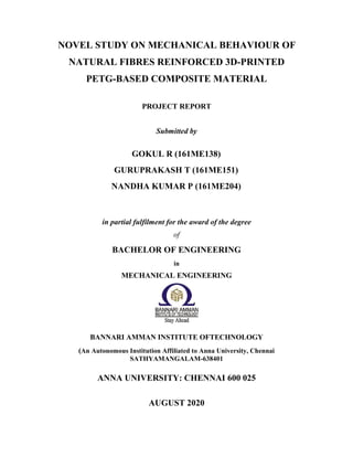
5.3.1 Sisal Fibre
Figure 5.15 Comparison of Sisal Fibre’s B-Force
From the above results (Figure 5.15), it is observed that KOH have
maximum B-Force among other solutions. Since the Breaking force decreases in
the order KOH > H2O2 > CaCO3 > Ba(OH)2 > NH4OH > NaOH.
5.3.2 Banana Fibre
Figure 5.16 Comparison of Banana Fibre’s B-Force
KOH NaOH NH4OH CACO3 BAOH2 H2O2
Salt solutions
365.8
307.7
397.2
351.1
422.5
603.1
700
600
500
400
300
200
100
0
Banana Fibre
B-FORCE
(grams)
KOH NaOH NH4OH CACO3 BAOH2 H2O2
Salt Solutions
567.1
602.3
536.6
497.6
740.1
888.6
1000
800
600
400
200
0
Sisal Fibre
B-FORCE
(grams)
56. 44
From the above results (Figure 5.16), it is observed that KOH have
maximum B-Force among other solutions. Since the Breaking force decreases in
the order KOH > NH4OH > Ba(OH)2 > H2O2 > NaOH > CaCO3.
5.4 Composite Preparation
By selecting 2% of Concentrated KOH at 30 min soaking time, using the
3D- Printing technique, PETG as the filler material, after setting all the printing
properties, the specimen is fabricated and post processing was done. Figure 5.17
shows the sample specimen of fabricated composite.
Figure 5.17 Sample Fabricated Specimen
After the specimens are fabricated, it has subjected to for different
Mechanical behaviour test which includes tensile test, Impact test, Hardness test
and Flexural test to understand its behaviour.
5.5 MECHANICAL TEST RESULTS
This type of tests helps to understand the strength and ductility of specimens
developed.
5.5.1 TENSILE TEST
The tensile test specimens are prepared according to ASTM standards and
the results obtained are plotted in Figure 5.18. This test also clearly indicates the
tensile expansion for the various laid pattern of the composite.
57. 45
Figure 5.18 Tensile Test Results
The above graph shows the results of three tensile specimens and its average
of three different patterns. From the graph, Tri- Hexagonal pattern have the
more tensile strength than the Zig-Zag and Cross 3D pattern. The Figure 5.19
shows the tensile test specimen after tested.
Figure 5.19 Tensile Strength Tested Specimen
5.5.2 IMPACTTEST
The test specimen is prepared according to its ASTM standards and Izod
Impact Test is carried out and the results were plotted in the Figure 5.20.
Fill Orientation
Cross-3D
Zig-Zag
Tri-Hexagonal
1.83
1.81
1.82
1.86
1.85 1.87 1.86
1.86
1.96 1.95
1.93
2
1.95
1.9
1.85
1.8
1.75
1.7
Average
Specimen 3
Specimen 2
Specimen1
2.03
Tensile Test
Stress(KN/mm2)
58. 46
Figure 5.20 Izod Impact Test Results
The above graph shows the results of three impact test specimen and its
average of three different patterns. From the graph, Zig-Zag pattern have the
more impact strength than Tri-Hexagonal and Cross-3D pattern. Figure 5.21
shows the tensile test specimen after tested.
Figure 5.21 Impact Strength Tested Specimen
5.5.3 FLEXURALTEST
The test specimen is prepared according to its ASTM standards and Flexural
test is carried out and the results were plotted in the Figure 5.22
Tri-Hexagonal Zig-Zag Cross-3D
Fill Orientation
1.96 2.03 1.92 1.97
1.61
1.58 1.6
1.65
2.52 2.4
2.71
2.55
3
2.5
2
1.5
1
0.5
0
Average
Specimen 3
Specimen1 Specimen2
Impact Test
Impact
Energy
(J)
59. 47
Figure 5.22 Flexural Test Results
The above graph shows the results of three flexural test specimens and its
average for better understanding. From the graph, Tri- Hexagonal pattern have
the more flexural strength than the Zig-Zag and Cross 3D pattern. Figure 5.23
shows the tensile test specimen after tested.
Figure 5.23 Flexural Strength Tested Specimen
5.5.4 HARDNESS TEST
The test specimen was prepared and tested in three different areas to get
better results and result were plotted in the Figure 5.24
3
2.5
2
1 . 5
LOAD (kg)
0
1
0.5
0
0.9
1.1
0.1
0
0
0
1.6
1.8
2
2.2
3.1
3.8
4
5.4
6
8.6
7.2
10
8
Cross-
3D
Zig-
Zag
Tri-
Hexagonal
FLEXURAL
TEST
DEFLECTION
(mm)
60. 48
Figure 5.24 Hardness Test Results
The above graph shows the results of hardness test specimen and its average
for clear idea. From the graph, Cross 3D pattern have the more flexural strength
than the Zig-Zag and Tri- Hexagonal pattern. Figure 5.25 shows the tensile test
specimen after tested.
Figure 5.25 Hardness Tested Specimen
Fibre’s get bonded micro structurally between polymer as like reinforced
iron rod in between concrete which automatically increase load bearing capacity
and life. The orientation of printing also plays a major role because it defines
the bonding between the layers. For different mechanical properties it is
observed that different orientation becomes preferred.
Cross-3D
Zig-Zag
Fill Orientation
Tri-Hexagonal
64
59
58
56
61
58
71
69
65
74
77
75
80
70
60
50
40
30
20
10
0
Hardness Test
Specimen1 Specimen2 Specimen3 Average
RHB
61. 49
CHAPTER 6
CONCLUSIONS
Now a days 3D printed component are most widely used for various
purposes, but its properties like Tensile, Impact, etc. can be improved by using
of various methods. Using chemically treated natural fibre without use of 100%
infill material had improved properties at a huge level. In this project work the
new combinations are developed and various mechanical tests are done and
obtained results are compared and listed below:
Fibre strength
Sisal Fibre and Banana Fibre treated for 30 minutes of 2% KOH had
improved Mechanical strengths of fibres compared to other chemical.
Mechanical properties
Tensile test: Tri hexagonal orientation has more strength approximately
1.05 times than zigzag and cross 3D orientations.
Impact test: Zig-zag orientation has more strength nearly 1.42 times than
tri hexagonal and cross 3Dorientation.
Flexural test: Tri hexagonal orientation has more strength about 1.65
times than zig-zag and cross 3Dorientations.
Hardness test: Cross 3D orientation has more strength around 1.21 times
than zig-zag and tri hexagonal orientations.
All this test helps in better understanding of components under the influence
of these fibres.
62. 50
FUTURE SCOPES
Since these fibres are tested under the different orientation structures of
3D printer, it can test under different infill percentage of material.
Like PETG there are many other materials like Polylactic Acid (PLA),
Acrylonitrile Butadiene Styrene (ABS), and Polyamide (PA) available for
printing that can be also tried.
Fibre are laid in between the component by manually, development of 3D
Printer which can even print fibre are done.
63. 51
REFERENCES
1) Anoop Kumar Sood. Ohdar, R.K. and Mahapatra, S. (2010), “Parametric
Appraisal of Mechanical Property of Fused Deposition Modelling Processed
Parts”, Materials and Design, Vol. 31, No. 1, pp.287-295.
2) Arpitha, G.R. Sanjay, M.R. Laxmana Naik, L. and Yogesha, B. (2014),
“Mechanical Properties of Epoxy Based Hybrid Composites Reinforced with
Sisal/SIC/Glass Fibres”, International Journal of Engineering Research and
General Science, Vol. 2, No. 5, pp.398-405.
3) Behzad Rankouhi. Sina Javadpour. Fereidoon Delfanian. and Todd Letcher.
(2016), “Failure Analysis and Mechanical Characterization of 3D Printed
ABS with Respect to Layer Thickness and Orientation”, Journal of Failure
Analysis and Prevention, Vol. 16, No. 3, pp. 467-481.
4) Carmen R. Rocha. Angel R. Torrado Perez, David, A. Roberson, Ryan B.
Wicker. and Corey M. Shemelya. (2014), “Novel ABS-based binary and
ternary polymer blends for material extrusion 3D printing”, Journal of
Material Research, Vol. 29, No. 17, pp. 1859-1866.
5) Chaithanyan, C. Panneerselvam, T. Raghuraman, S. and VijayaRamnath, B.
(2014), “Investigation of Tensile behaviour of Sisal and Coir Reinforced
Hybrid Composites using Vinyl Ester Resin”, Applied Mechanics and
Materials, Vol. 591, pp.146-149.
6) Cifuentes, S.C. Frutos, E. Benavente, R. Lorenzo, V. and González Carrasco,
J.L. (2017), “Assessment of mechanical behaviour of PLA composites
reinforced with Mg micro- particles through depth-sensing indentations
analysis”, Journal of the Mechanical Behaviour of Biomedical Materials,
Vol. 65, pp.781-790.
7) Dharmalingam, G. Kumar, V. and Sengolerayan, A. (2018), “Mechanical
Behaviour of Treated and Untreated Sisal-Kenaf Hybrid Composite
Materials”, International Journal of Mechanical and Production Engineering
Research and Development, Vol. 8, Issue 3, pp. 39-50.
64. 52
8) Hariprasad, T. Dharmalingam, G. and Praveen Raj, P. (2013), “A Study of
Mechanical Properties of Banana-Coir Hybrid Composite Using
Experimental and Fem Techniques”, Journal of Mechanical Engineering and
Sciences, Vol. 4, No. 4, pp.518-531.
9) Hemant Patel. Ashish Parkhe. and Shrama, P.K. (2016), “Mechanical
Behaviors of Banana and Sisal Hybrid Composites Reinforced with Epoxy
Resin”, International Journal of Research-Granthaalayah, Vol. 4, No. 1,
pp. 206-216.
10) Isiaka Oluwole Oladele. Oluyemi Ojo daramola. and Solomon Fasooto.
(2014), “Effect of Chemical Treatment on the Mechanical Properties of Sisal
Fibre Reinforced Polyester Composites”, Leonardo Electronic Journal of
Practices and Technologies, Vol. 13, No. 24, pp. 1-12.
11) Jaya Christiyan, K.G. Chandrasekhar, U. and Venkateswarlu, K. (2016), “A
study on the influence of process parameters on the Mechanical Properties of
3D printed ABS composite”, Materials Science and Engineering, Vol. 114,
No. 1, pp.1-8.
12) Jung Tae Lee. Myung Wook Kim. Young Seok Song. Tae Jin Kang. and Jae
RyounYoun. (2010), “Mechanical Properties of Denim Fabric Reinforced
Poly (lactic acid)”, Fibres and Polymers, Vol. 11, No. 1, pp.60-66.
13) Kumaresan, M. Ramesh, N. Ramesh, S. Vijay, S. and Benjamin Lazarus, S.
(2017), “Review on Mechanical Behaviour of Sisal & Banana Fibre
Reinforced Polymer Composites”, Advanced Research in Management
Engineering Technology, Vol. 2, No. 1, pp. 350-355.
14) Layth Mohammed. Ansari, M.N.M. Mohammad Jawaid. and Saiful Islam,
M. (2015), “A Review on Natural Fiber Reinforced Polymer Composite and
its Applications”, International Journal of Polymer Science, Vol. 2015,
pp. 1-15.
15) Paulina Latko Durałek. Kamil Dydek, Emila Golonko. and Anna
Boczkowska. (2018), “Mechanical Properties of PETG Fibres and Their
Usage in Carbon Fibres/Epoxy Composite Laminates”, Fibres and Textiles in
Eastern Europe, Vol. 26, No. 2, pp.61-65.
65. 53
16) Ravi Ranjan, Bajpai, P.K. and Tyagi, R.K. (2013), “Mechanical
Characterization of Banana/Sisal Fibre Reinforced PLA Hybrid Composites
for Structural Application”, Engineering International, Vol. 1, No. 1,
pp. 39-49.
17) Santhosh, J. Balanarasimman, N. Chandrasekar, R. and Raja, S. (2014),
“Study of Properties of Banana Fibre Reinforced Composites”, International
Journal of Research in Engineering and Technology, Vol. 3, No. 11,
pp.144-150.
18) Selin, J.F. Oksman, K. and Skrifvars, M. (2003), “Natural fibres as
reinforcement in polylacticacid (PLA) composites”, Composites Science and
Technology, Vol.63, No. 9, pp.1317-1324.
19) Xiaoyong Tian. Tengfei Liu. Chuncheng Yang. Qingrui Wang. and Dichen
Li. (2016), “Interface and performance of 3D printed continuous carbon fibre
reinforced PLA composites”, Composites Part A, Vol. 88, pp.198-205.
20) Yuvaraj, G. Vijaya Ramnath, B. Abinash, A. Srivasanand, B. and Vikas
Nair, R. (2016), “Investigation of Mechanical Behaviour of Sisal Epoxy
Hybrid Composites”, Indian Journal of Science and Technology, Vol. 9,
No. 34, pp.1-7.
66. 54
ANNEXURE I
INDIVIDUAL WORK CONTRIBUTION
Student Name: NANDHA KUMAR P Register Number: 161ME204
1. Fibre Selection and Chemical Treatment
This project aims to discover a new breakthrough in Polymer Material
Composite.
Various team members contributed individually in different set of areas in
the total research work carried. My work was mostly associated with
starting stage of the research work.
Based on several Literature Survey the commonly and cheaply available
fibres and also according to its degrading nature, from natural fibres,
Banana and Sisal [4] fibres were chosen.
After choosing fibres, Fibres were collected from the local cultivators and
extracted from the plant accompanied by soaking, scraping and
decorticators.
The extracted fibres were dried in sunlight as long as moisture content
available.
The single yarn fibre is treated with different Alkali solutions [3] to
remove the lignin and wax present in the surface of the fibre as well as to
improve the interfacial bonding strength.
The Alkali solutions include KOH, NaOH, CaCO3, Ba(OH)2, NH4OH
and H2O2 [3].
The solution is prepared with three different concentration (2%, 4% and
6%) to identify better Breaking Strength for three different soaking rates
(30 min, 60 min and 90 min).
67. 55
These chemically treated fibres were subjected to single yarn fibre strength
in UniStretch 250 multi Strength Tester machine. It works on the principle
of Constant Load Extension (CRE) where the Breaking Force is
calculated.
The fibre was fixed between two jaws of the machine. Upper jaw is fixed
and lower jaw move downwards where the fibre gets elongated downwards
in the direction of load.
While testing, some of the fibres were cut down before it starts to elongate.
To solve this issue, three or more extra single yarn fibres were chemically
treated for this purpose.
The Breaking Force (grams) for the different combinations was obtained
and 2% KOH for 30 minutes [2] gave the greater Breaking Force for both
Sisal and Banana fibres. These results able to conclude that longer period
of soaking rate and high concentration will loosen the strength of the fibre.
PETG was selected as a polymer material and composite was fabricated
using Additive Manufacturing for three different fill orientations.
These composites were subjected to Mechanical Tests which was better to
examine that chemically treated fibres PETG Composite have better
strength compared its original strength.
Finally, this research was presented in an International Conference and
suggestions from the experts were noted down for the future work.
Name and Signature of Student
68. 56
Student Name: GOKUL R Register Number: 161ME138
2. Polymer Composite Preparation using 3D-Printing
This project focuses to discover a new step forward in Polymer Material
Composite.
The team members contributed individually in different set of areas in the
total research work carried. My work was mostly associated with middle
stage of the research work.
Natural fibres were selected based on several factors and these fibres were
treated with chemical solutions for various reasons.
PETG was chosen as polymer material because of its strength [15] and
low cost.
Test to be performed after composite preparation was known prior to
design according to its ASTM standard [2].
Composite is fabricated using Additive Manufacturing by 3D-Printing.
Using SOLIDWORKS, design of the fabrication [7] composite were
made and converted into .STL format.
Designs were copied to ULTIMAKER CURA software for Printing and
PETG filament was fitted to flow through nozzle.
Before starting fabrication, parameters which include nozzle temperature,
amount of fill orientations, etc.
Sometimes before starting fabrication origin for nozzle in printer bed must
be ensured. To avoid printing irregular shapes.
Fill orientations like Zig-Zag, Tri-Hexagon and Cross-3D were selected
because it has high fill density compared to other fill orientations.
Once these parameters were selected, ANYCUBIC 3D-Printer was used
to fabricate where the chemically treated fibre was inserted in ratio of 1:3
to the layers of printing.
69. 57
While printing sometimes printer was subjected to power fluctuations and
this may cause small deviation in specimen. To avoid this problem for
each test three specimens are prepared.
After specimen was printed, it was subjected to cleaning for removing
small piece stick with specimen and same process was repeated for other
two fill orientations.
These specimens were subjected to mechanical tests which was necessary
to determine mechanical properties of composites.
Once this research work was completed, it was presented in the
International Conference and got expert ideas for further works.
Name and Signature of Student
70. 58
Student Name: GURUPRAKASH T Register Number: 161ME151
3. Mechanical Testing of Specimen and Analysis
This project was undertaken in view of new research breakthrough in
Polymer material composite.
The team members contributed individually in set of areas of the total
research work carried. My area of work was mostly affiliated in the final
stage of the research work.
After the process of fiber selection and fabrication of the new material
composite, the composite was subjected to various Mechanical tests. All
the different Mechanical tests and result analysis were solely carried out
by me with some interrogation from my team members and the guide.
Various tests taken are Tensile test, Impact test, Flexural test and
Hardness test [9]. The entire composite was tested based on their ASTM
standards and with utmost level of accuracy.
The conclusion to take the tests was decided based on our literature
survey and with some inputs from our guide. I carefully sorted out the
best Mechanical tests to be taken for the specimen for better results and
conclusion to be made.
In the case of Tensile testing the specimen was accordingly fit in the FIE
Universal Tensile Tester. The specimen was subjected to constant
elongation at fixed load and results were noted for further evaluation [11].
For Hardness test the specimen surface was made indent with Diamond
Indenter. The indenter was made to strike at different areas of the
surface for best result. Readings were noted for further evaluation [14].
In Flexural test the specimen was fixed at the two ends and the centre
load was applied at center of the specimen. At the maximum distortion
of the specimen, the readings were noted out [9].
71. 59
For Impact test, Izod method was preferred. The specimen was fixed at a
fixed point and striker was made to hit the specimen from a certain
elevation [6].
I did face quite a difficulty while doing the tests, sometimes the specimen
would break at different point than the exact point and the test results
would greatly deviate from the actual. Luckily, I did have an extra
specimen for the all the tests taken.
All test result was studied and graphs were plotted out accordingly. The
results were compared with the existing raw PETG Polymer (PETG
composite showed greater improvement in all Mechanical tests taken in
comparison with the raw PETG material) and with different other added
elements material (Results varied in comparison with addition of different
additives).
Based on the comparative study, conclusions and suggestions were
made. This also provoked us in indulging in further research work in new
material development.
At the last the research was even presented in an International conference
and suggestions from the expert panel were also noted down for further
research work to be carried out.
Name and Signature of Student