1. Features
Individually addressed wall mount audible/visible
notification appliances with efficient electronic
horn and high intensity xenon strobe provides:
x Supervision of each individual appliance’s wiring and
connections
x Ability to connect using “T” tapping for Class B/Style 4
circuits to simplify wiring (Class A/Style 6 circuits
require in/out wiring)
x Horns controlled separately from strobes on the same
two-wire circuit allowing “on-until-silenced” and
“on-until-reset” using a single address
x Compatibility with ADA requirements (refer to
important installation information on page 3)
x In/out wiring accessibility from front of housing
providing easy access for installation, inspection, and
testing
x Magnetic test diagnostics to assist checkout and testing
of appliances and wiring
x Rugged, high impact, flame retardant thermoplastic
housings available in red or white (covers are available
separately to convert color)
LED indicator and magnetic test feature:
x LED indicator can be selected to display each polling
cycle to indicate appliance supervision
x When the TrueAlert addressable channel controller is in
diagnostic mode, the magnetic test pulses the LED to
indicate appliance address and is selectable to also
briefly flash the strobe to confirm operation
TrueAlert two-wire addressable control of visible
and audible notification activates appliances with:
x Visible appliances connected to the same circuit
operated at a synchronized 1 Hz flash rate
x Horns sounded as Temporal or March Time pattern, or
on continuously, controlled separately from visible
appliances on the same two-wire circuit
x Horn March Time is available as 60 or 120 beats per
minute
TrueAlert addressable notification appliance
design provides flexible, easy, and convenient
flush or surface wall box mounting:
x Rear of housing does not extend into box and easily
mounts to single gang, double gang, or 4-inch box
x In/out wiring terminals, 18 AWG to 12 AWG
x Optional mounting adapters are available to cover
surface mounted electrical boxes and to adapt to
Simplex®
2975-9145 boxes
* These products have been approved by the California State Fire Marshal (CSFM)
pursuant to Section 13144.1 of the California Health and Safety Code. See CSFM Listing
7125-0026:239 for allowable values and/or conditions concerning material presented in
this document. It is subject to re-examination, revision, and possible cancellation.
Accepted for use – City of New York Department of Buildings – MEA35-93E. Additional
listings may be applicable; contact your local Simplex product supplier for the latest
status. Listings and approvals under Simplex Time Recorder Co. are the property of
Tyco Safety Products Westminster.
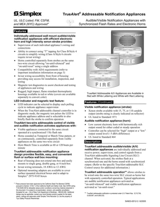
TrueAlert Addressable A/V Appliances are Available in
Red with White Lettering and White with Red Lettering
Features (Continued)
Visible notification appliance (strobe):
x Xenon strobe available with 15, 75, or 110 candela
output (strobe rating is clearly indicated on reflector)
x UL listed to Standard 1971
Audible notification appliance (horn):
x Low current electronic horn with harmonically rich
output sound for either coded or steady operation
x Controller can be selected for “high” output or a “low”
output sound level (~5 dBA difference)
x UL listed to Standard 464
Description
TrueAlert addressable audible/visible (A/V)
notification appliances are individually addressed and
receive power, supervision, and control signals from a
TrueAlert addressable Signaling Line Circuit (SLC)
channel. When activated, the strobes flash at a
synchronized rate and the horns sound with synchronized
output. (Refer to the specific TrueAlert addressable SLC
Control source for additional information.)
TrueAlert addressable operation** allows strobes to
be wired onto the same two-wire SLC circuit as horns but
with separately controlled operation. Typical applications
are audible notification appliances activated as
“on-until-silenced” and visible notification appliances
activated as “on-until-reset.”
** TrueAlert addressable notification is protected under U.S. Patent Nos. 6,313,744;
6,426,697; and 6,693,532.
TrueAlert®
Addressable Notification Appliances
UL, ULC Listed; FM, CSFM, Audible/Visible Notification Appliances with
and MEA (NYC) Approved* Synchronized Flash Rates and Electronic Horns
S4903-0012-3 6/2005
2. TrueAlert Addressable Advantage
Background. Fire alarm control panels typically
activate both audible and visible notification upon receipt
of an alarm. At the direction of an authorized operator (or
by pre-determined program), audible notification
appliances may be silenced before the alarm condition is
reset (on-until-silenced) while the visible notification
appliances are kept activated until the alarm condition is
reset (on-until-reset). This operation has traditionally
required two different circuits (four-wire operation).
TrueAlert addressable operation provides separate
audible and visible appliance control functions using a
single two-wire circuit that also confirms connection to
the individual notification appliance’s electronic circuit.
This operation increases circuit supervision integrity by
providing supervision that extends beyond the appliance
wiring connections.
Opportunities for Reducing Installation and
Testing Time. Allowing separate controls to be carried
on the same two-wire SLC can significantly reduce
installation time and expense for both retrofit and new
construction. When Class B (Style 4) wiring is used,
wiring can be “T” tapped, allowing even more savings in
distance, wire, junction boxes, and overall installation
efficiency. The magnetic test feature (see next paragraph)
also can provide improved installation efficiency.
TrueAlert Addressable Control
TrueAlert addressable notification appliances are
controlled by:
x The 4009-9401 TrueAlert Addressable Controller
interface panel connected between the host fire alarm
control panel and the addressable notification appliances
(refer to data sheet S4009-0003 for further information
about the TrueAlert Addressable Controller)
x A TrueAlert Addressable Power Supply in a 4100U fire
alarm control panel (refer to data sheet S4100-0031)
TrueAlert Addressable Diagnostics
Test Features. The TrueAlert Addressable Controller
can be selected to pulse each appliance’s LED when that
appliance receives a supervision poll. When the
Controller is selected for diagnostic mode, the addressable
appliance magnetic test feature provides a response at the
individual appliance being tested.
Silent Appliance Testing. In this test mode, in
response to the magnetic test, the appliance LED pulses
sequentially to conveniently indicate the appliance’s
address.
Operational Appliance Testing. The LED diagnostic
test mode can be selected at the TrueAlert Addressable
Controller such that after the address is indicated, the
strobe will briefly flash and the horn will briefly sound to
indicate proper operation.
2 S4903-0012-3 6/2005
TrueAlert Addressable Audible/Visible Notification Appliances
Strobe Output Rating
Model Number
15 cd 75 cd 110 cd
Housing Color
4903-9450
4903-9451
4903-9452
Red with white
“FIRE” lettering
4903-9453
4903-9454
4903-9455
White with red
“FIRE” lettering
Mounting Adapters
Model Description Dimensions
4905-9937 Surface mount red adapter skirt
4905-9940 Surface mount white adapter skirt
Use to cover 1-1/2” deep
surface mounted boxes
5-3/8” H x 5-1/4” W x 1-5/8” D
(136 mm x 133 mm x 41 mm)
Total depth with horn = 3-1/8” (79 mm)
4905-9931
Adapter plate, red, for mounting to Simplex 2975-9145 Box
(typically for retrofit, may be mounted vertical or horizontal)
8-5/16” x 5-3/4” x 0.060” Thick
(211 mm x 146 mm x 1.5 mm)
2975-9145 Red mounting box, requires 4905-9931 adapter plate
7-7/8 x 5-1/8 x 2-3/4 D
(200 mm x 130 mm x 70 mm)
Optional Covers and Guard
Model Description Dimensions
4905-9994 Red A/V cover with white “FIRE” lettering
4905-9995 White A/V cover with red “FIRE” lettering
For replacement or
color conversion
5-1/8” H x 5” W x 1-1/2” D
(130 mm x 127 mm x 38 mm)
4905-9961
Wire guard with mounting plate, red, compatible with surface or
semi-flush mounted boxes*
6-1/16” H x 6-1/16” W x 3-1/8” D
(154 mm x 154 mm x 79 mm)
* UL listing in process as of document revision date (by Space Age Electronics Inc.).
Product Selection
3. 3 S4903-0012-3 6/2005
2
1
3
4
Removable cover
(tool required)
Mounting is compatible with
single gang, double gang, and
4 (102 mm) square boxes,
1-1/2 (38 mm) deep, by others
Mounting Holes:
4 square (4)
Single gang (2)
Double gang (3)
Wiring access hole
Wiring terminals
Transparent housing
and lens assembly
LED indicator
Address setting dipswitch
Magnetic test location
Optional
4905-9961
Wire Guard
4 square box profile,
1-1/2 (38 mm) deep
(Surface mount conduit and
box shown for reference)
Optonal surface mount adapter skirt,
1-1/2 deep: 4905-9937, Red; 4905-9940, White
(conduit knockouts are provided on all four sides)
TrueAlert
Addressable A/V
2975-9145 Box Mounting Side View, Adapter Skirt
and Wire Guard
2975-9145 Box
4905-9931 Adapter Plate
4905-9931 Adapter Plate
4905-9961 Optional Wire Guard
(shown here for reference only, can be used on other mounting options)
TrueAlert
Addressable A/V
IMPORTANT ! INSTALLATION
MOUNTING HEIGHT REFERENCE
a
NFPA 72 requires
that the entire lens
be not less than
80 and not greater
than 96 above the
finished floor.
Electrical
box outline
80 (2.03 m)
minimum
Bottom of lens
is either even
with, or slightly
above bottom
of compatible
boxes
Installation Reference
Adapter Plate and Wire Guard Installation Reference