Call for Papers - Educational Administration: Theory and Practice, E-ISSN: 21...
Chapter 5.pdf
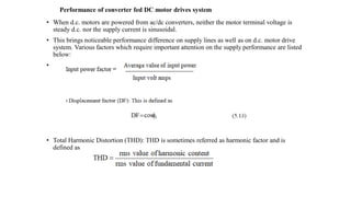
1. Performance of converter fed DC motor drives system
• When d.c. motors are powered from ac/dc converters, neither the motor terminal voltage is
steady d.c. nor the supply current is sinusoidal.
• This brings noticeable performance difference on supply lines as well as on d.c. motor drive
system. Various factors which require important attention on the supply performance are listed
below:
• .
• Total Harmonic Distortion (THD): THD is sometimes referred as harmonic factor and is
defined as
2. Single phase full converter fed drive
• Assuming that the motor current is ripple-free and its amplitude is , the supply voltage, and
source current is are plotted in Fig.5.7(a).
π t
s
2
a
I
s
v
0
2
s
s i
v ,
s
i
a
I
0
ia=Ia
t
s
a
a i
v ,
π
α
2
(a)
(b)
Fig.5.7. (a) Supply voltage and current with full converter fed d.c. motor.
(b) Waveforms of va and ia
a
v
6. Single-phase semi-converter fed drive
• In a single-phase semi-converter, free-wheeling is inherent and
during this interval, source current is zero.
• With a constant armature current, Ia, the supply voltage and current
of a single-phase semi-converter is sketched in Fig.5.8.
Fig.5.8. (a) Supply voltage and current waveforms with semiconverter.
(b) Waveforms of va and ia
(a)
(b)
ia=Ia
t
s
a
a i
v ,
π
2
α
0
-Ia
Ia
0 π
2 t
s
s
s i
v ,
a
v
10. Comparison of input performance parameters of single-phase full converter
and semi-converter fed DC motor drive
• From the expressions derived in previous sections, now it is possible to compare the input performance of a d.c. motor drive
with full and semi converters.
• The comparison is performed by taking output voltage of the converter as an independent variable, since this value is different
for the two converters for the same α.
• The average value of output voltage of a full converter with continuous motor current is taken from equation is
11. • For different values of α, p.u. output voltages of full and
semi converters are evaluated using equation (5.38) and
equation(5.39).
• Input performance parameters of the two converters are
then evaluated using equations (5.26), (5.27), (5.28),
(5.35), (5.36) and (5.37).
• The variation of performance parameters of the two
converters is shown in Fig.5.9.
• It is evident that semi-converter exhibits improved power
factor and displacement factors. It possesses higher THD
at reduced voltage (up to 0.5 p.u.), but THD falls
thereafter.
(a)
(b) (c)
Fig.5.9. Plot between performance parameters and per-unit voltage for semi-converter and full converter. (a) Input power factor versus p.u. voltage.
(b) Displacement factor versus p.u. voltage. (c) Total Harmonic Distortion versus p.u. voltage