ABSTRACT
The switching mode power supply market is flourishing quickly in today’s world. Design engineers aren’t always supplied with the desired amount of voltage they need in order to make their design function properly. Adding an extra voltage supply to a design is not always cost efficient. This project is proposed to provide a method of boosting DC voltage from 5 Volts to 15 Volts, by using a boost converter designed specifically for this task. All aim, calculations, tests, data and conclusions have been documented within this project. Results of simulation show that the switching converter will boost voltage from 5 volts to 15 volts with power conversion efficiency of 94.16 percent.
1. Boost Converter and analysis its
characteristics
ABSTRACT
The switching mode power supply market is flourishing quickly in today’s
world. Design engineers aren’t always supplied with the desired amount of
voltage they need in order to make their design function properly. Adding an
extra voltage supply to a design is not always cost efficient. This project is
proposed to provide a method of boosting DC voltage from 5 Volts to 15 Volts,
by using a boost converter designed specifically for this task. All aim,
calculations, tests, data and conclusions have been documented within this
project. Results of simulation show that the switching converter will boost
voltage from 5 volts to 15 volts with power conversion efficiency of 94.16
percent.
INTRODUCTION
In many technical applications, it is required to convert a set voltage DC source
into a variable-voltage DC output. A DC-DC switching converter converts
voltage directly from DC to DC and is simply known as a DC Converter. A DC
converter is equivalent to an AC transformer with a continuously variable turns
ratio. It can be used to step down or step up a DC voltage source, as a
transformer.
DC converters are widely used for traction motor control in electric
automobiles, trolley cars, marine hoists, forklifts trucks, and mine haulers. They
provide high efficiency, good acceleration control and fast dynamic response.
They can be used in regenerative braking of DC motors to return energy back
into the supply. This attribute results in energy savings for transportation
systems with frequent steps. DC converters are used in DC voltage regulators;
and also, are used, with an inductor in conjunction, to generate a DC current
source, specifically for the current source inverter
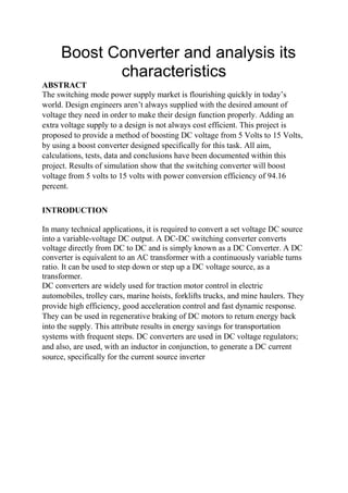
2. GENERAL BOOST CONVERTER CONFIGURATION
In a boost converter, the output voltage is greater than the input voltage – hence the name
“boost”. A boost converter using a power MOSFET is shown below.
Fig.-1 Circuit diagram of Boost Converter
The function of boost converter can be divided into two modes, Mode 1 and Mode 2. Mode 1
begins when transistor M1 is switched on at time t=0. The input current rises and flows through
inductor L and transistor M1.
Mode 2 begins when transistor M1 is switched off at time t=t1. The input current now flows
through L, C, load, and diode Dm. The inductor current falls until the next cycle. The energy
stored in inductor L flows through the load
The circuits for the two modes of operation are shown below:
4. Fig. 3
BLOCK DIAGRM
Fig-4 shows the basic blocks of building a boost converter circuit:
Fig.-4 Block diagram Boost Converter
The voltage source provides the input DC voltage to the switch control, and also to the magnetic
field storage element. The block which contains switch control directs the action of the
switching element, whereas the output rectifier and filter deliver an acceptable DC voltage to
the output.
Magnetic Field Storage
Element
Voltage source
Switch
Control
Switching
Element
Output
Rectifier
5. 3.3 SPECIFICATIONS
Engineers working in today’s high-tech environment have to deal with a rapidly changing market
of electronic products and equipment. As new technologies are invented, integrated circuits
function faster and are smaller in size and shape. But, many integrated circuits still require a
voltage of 15 volts to function. The DC-DC Switching Boost Converter will take a 5 Volt DC
voltage supply with 10 % tolerance and deliver 15 Volts to the load. The maximum current
delivered to the load will be 0.4 A. The circuit will operate with a minimum efficiency of 94.16%.
Input DC Voltage = 15V
Load Resistance= 37.5Ω
Capacitance C= 2.2mF
Inductance L= 76.8µH
Simulink diagram of boost converter:
Fig-5 Circuit Diagram of Boost Converterr in MATLAB
6. Fig-6 wave form of load current and load voltage
CONCLUSION
All of the specifications stated previously have been met by this boost converter design.
MATLAB using parameters were performed and corresponding waveforms were obtained. The
output voltage across the output capacitor or load should be 15V but we have got it is approx.
18V, and current through the load is 0.5A. The power efficiency of the circuit exceeds 94 %.
However, an additional constraint needs to be put on the load. The load must not exceed 0.75kΩ.
This will cause the efficiency to fall below the specified value of 94.16%. Hardware design of
BOOST CONVERTER was done. It is observed, by varying duty cycle output voltage also
changes.
REFERENCES
[1] Dr. P.S. Bhmibra, “Power Electronics,” Third Edition, 2004
[2] Muhammad H. Rashid, “Power Electronics, Circuits, Devices, and Applications”, Third
Edition, Pearson Education, Inc., 2004.
[3] G. Seguier, “Power Electronic Converters: DC-DC Conversion”, New York, Springer-
Verlag,
[4] www.ieeexplore.ieee.org/Proposition and performance analysis of a DC/DC boost converter