
Recommended
More Related Content
Similar to 16 mt6201 industrial automation and control qb
Similar to 16 mt6201 industrial automation and control qb (20)
Recently uploaded
Recently uploaded (20)
16 mt6201 industrial automation and control qb
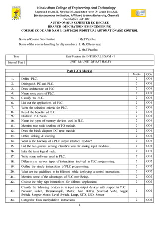
- 1. 1 Hindusthan College of Engineering And Technology Approved by AICTE, New Delhi, Accredited with ‘A’ Grade by NAAC (An Autonomous Institution, Affiliated to Anna University, Chennai) Coimbatore – 641 032 AUTONOMOUS SEMESTER UG DEGREE BRANCH: MECHATRONICS ENGINEERING COURSE CODE AND NAME: 16MT6201 INDUSTRIAL AUTOMATION AND CONTROL Name of Course Coordinator : Mr.T.Prabhu Name of the course handling faculty members : 1. Mr.K.Kesavaraj 2. Mr.T.Prabhu Test Unit/Portions for INTERNAL EXAM - I Internal Test 1 UNIT 1 & UNIT 2(FIRST HALF) PART A (2 Marks) Marks COs 1. Define PLC. 2 CO1 2. Distinguish PC and PLC. 2 CO1 3. Draw architecture of PLC 2 CO1 4. Name some parts of PLC. 2 CO1 5. Classify the PLC. 2 CO1 6. List out the applications of PLC. 2 CO1 7. Write the selection criteria for PLC. 2 CO1 8. Recall the benefits of PLC. 2 CO1 9. Illustrate PLC Scan. 2 CO1 10. Name the types of memory devices used in PLC. 2 CO1 11. Mention two basic sections of I/O module. 2 CO1 12. Draw the block diagram DC input module 2 CO1 13. Define sinking & sourcing 2 CO1 14. What is the function of a PLC output interface module? 2 CO1 15. List the two general sensing classifications for analog input modules. 2 CO1 16. Infer the term logical rack. 2 CO1 17. Write some software used in PLC. 2 CO1 18. Differentiate various types of instructions involved in PLC programming. 2 CO2 19. Outline the simple instructions of PLC programming. 2 CO2 20. What are the guidelines to be followed while deploying a control instructions 2 CO2 21. Mention some of the advantages of PLC over Relays. 2 CO2 22. Choose the relay type instructions for different applications 2 CO2 23. Classify the following devices in to input and output devices with respect to PLC. Pressure switch, Thermocouple, Motor, Push Button, Solenoid Valve, toggle Switch, Stepper Motor, Level Switch, Lamp, RTD, LED, Sensor 2 CO2 24. Categorize Data manipulation instructions 2 CO2
- 2. 2 25. Write the ladder logic diagram for XOR 2 CO2 PART B(14 Marks) Marks COs 1. Draw and explain the basic architecture of PLC with neat block diagram. 14 CO1 2. Explain the principle of operation of discrete AC input and output modules used in PLC with suitable diagrams. 14 CO1 3. (i) Draw diagram of DC input module and write the operation of isolation of optical Isolator. (ii) Illustrate the concept of sinking type of DC input module 14 CO1 4. Describe the scan cycle with neat diagram in detail. 14 CO1 5. Compare discrete and analog I/O modules with respect to the type of input or output devices which they can be used. 14 CO1 6. Construct the relay ladder logic for mixer process control with neat diagram 14 CO1 7. Elaborate the different types of Communication networks of PLC with neat diagram 14 CO1 8. Explain the main function of each of the following major components of a PLC: a. Processor module (CPU) b. I/O modules c. Programming device d. Power supply module 14 CO1 9. Summarize the I/O PLC wiring with neat diagram. 14 CO1 10. List out the special I/O modules of PLC and explain any two modules in detail. 14 CO1 11. Describe basic instructions of ladder programming. 14 CO2 12. Discuss the use of math instructions of PLC for automatic control of upper and lower set point limits. 14 CO2 13. Classify the data manipulation instructions and explain in detail with logic diagram. 14 CO2 14. Explain Converting Simple Relay Diagram into PLC Relay Ladder Diagram for control process with neat sketch. 14 CO2 15. Discuss master control and Immediate I/O operations in program control instructions. 14 CO2 PART C( 10 Marks) 1. List few advantages of a PLC system over the traditional hardware control system. 10 CO1 2. Explain the PLC size and applications. 10 CO1 3. Discuss the installation of PLC in detail. 10 CO1 4. Discuss the various steps of verifications of PLC during installation. 10 CO1 5. How to connect the external components to PLC system 10 CO1 6. Write ladder logic for the following instructions A) Input in series B) Input in parallel C) Inputs in combination D) Inputs in multiple output action 10 CO2 7. Summarize the Math instructions used in PLC with Examples 10 CO2 8 Explain the selectable timed interrupt function. 10 CO2
- 3. 3 Test Unit/Portions for INTERNAL EXAM - II Internal Test 2 UNIT 2(SECOND HALF) &UNIT 3 PART A (2 Marks) 1. Write XIC in input instructions 2 CO2 2. Define OTE and OTL 2 CO2 3. What is ladder logic and ladder diagram? 2 CO2 4. Recall XIO in input instructions 2 CO2 5. Relate the following terms: i) Data transfer ii) Data Comparison 2 CO2 6. Give an example of a ladder diagram of simple ON OFF instructions 2 CO2 7. List any four commonly available relay ladder diagram instructions. 2 CO2 8. Infer Timer. 2 CO3 9. Select Counter for different applications. 2 CO3 10. What is retentive timer in PLC? 2 CO3 11. Differentiate On-delay and Off-delay timer instruction in PLC. 2 CO3 12. Classify the types of timers. 2 CO3 13. Sketch the ladder logic diagram for ON delay timer. 2 CO3 14. Define non retentive timer. 2 CO3 15. Relate the role of counter functions in PLC programming. 2 CO3 16. Compare TON and TOFF timer. 2 CO3 17. Where Cascading Counters are used? 2 CO3 18. Name some industrial applications of Counters. 2 CO3 19. Differentiate incremental and absolute encoder. 2 CO3 20. List the types of counters. 2 CO3 21. Define Encoder. 2 CO3 22. What is necessity for cascade timers? 2 CO3 PART B(14 Marks) 1. Describe the various programming languages used for PLC with neat diagram 14 CO2 2. Explain the safety circuitry of PLC installation in detail with logic diagram. 14 CO2 3. Explain the logical instructions in detail with an example. 14 CO2 4. Describe the EXAMINE ON and EXAMINE OFF with ladder program. 14 CO2 5. Discuss jump and subroutine operations in program control instructions. 14 CO2 6. Classify timers. Write briefly about each types of timers. 14 CO3 7. Explain the timer instructions along with an example. 14 CO3 8. Explain Retentive on delay timer instructions in a PLC with example 14 CO3 9. Explain up-counter instructions in a PLC with example. 14 CO3 10. When push button PB5 is pressed, start mixer M1 and M2 at an interval of 30 seconds each. During this time gap, ovens O1 and O2 are be turned on. Stop the mixers when PB5 is switched OFF. Draw the ladder diagram for this condition. 14 CO3 11. How are counters classified? Write briefly about each types of counters. 14 CO3
- 4. 4 12. A main conveyor has two conveyors, A and B, feeding it. Feeder conveyor A puts six-packs of canned soda on the main conveyor. Feeder conveyor B puts eight-packs of canned soda on the main conveyor. Both the feeder conveyor has counters that count the number of packs leaving them. Construct a PLC program to give a total can count on the main conveyor. 14 CO3 13. Close a valve V08, 20 seconds after a switch S08, is set OFF. During this time, motor M5 should run. Which instructions will you use for this condition? Draw the relevant ladder diagram. 14 CO3 14. Write a program that switches ON a light L1 if conveyor C1 runs 10times. If L1 is switched ON five times, motor M2 should switch ON. 14 CO3 15. An output K is turned by closing a momentary pushbutton switch PB1. Another output L is to go on 8 seconds after K goes on. L is then to remain no for an interval of 19 seconds and then turn off. Additionally, at times L is to be turned off and back on, during the 19 seconds run time. This is accomplished by closing another momentary pushbutton switch PB3 before PB1 is activated to turn on output K. the optional imbedded off time during the L 19 seconds interval starts 4 seconds after 19 seconds interval has started and continues for 6 seconds. The entire system is reset by a momentary push button switch PB2. 14 CO3 PART C(10 Marks) 1. Explain the purpose of math instructions applied to the PLC. 10 CO2 2. Discuss the purpose of the move with mask instructions. 10 CO2 3. When switch S3 is switched ON, start the solenoid coil C1.When S3 is switched OFF, stop C1 after 0.5 Sec. Draw the ladder diagram for this condition. 10 CO3 4. Write a program that will turn a light on when count reaches 20. The light is then to go off when a count of 30 is reached. 10 CO3 5. When a switch is turned on, ‘C’ goes on immediately and ‘D’ goes on 9 seconds later. Opening the switch turns both C&D off. 10 CO3 6. Explain the types of counters in detail with a proper example. 10 CO3 7. With an example explain programming counters in ladder logic diagram. 10 CO3 8. When switch S3 is switched ON, start the solenoid coil C1.When S3 is switched OFF, stop C1 after 0.5 Sec. Draw the ladder diagram for this condition. 10 CO3 Test Unit/Portions for MID SEMESTER EXAM Mid-Sem Test UNIT 1,2,3 & UNIT 4(FIRST HALF) PART A (2 Marks) Marks Cos 1. List a few industrial applications of PLC. 2 CO4 2. Classify the sensors used in PLC applications. 2 CO4 3. What is the purpose of Photoelectric sensor in PLC applications? 2 CO4 4. Write the applications of PLC in industrial applications. 2 CO4 5. Infer the grey painting system. 2 CO4 6. Draw a simple ladder logic diagram for bottle filling system. 2 CO4 7. Classify sensors used to find out the object presence I conveyor system in PLC. 2 CO4
- 5. 5 8. How limit switches are used in the Conveyor belt applications. 2 CO4 9. Write ladder logic diagram for material detection in running conveyor 2 CO4 10. Write ladder logic diagram for motor forward and reverse direction. 2 CO4 PART B( 14 Marks) Marks COs 1. Write a ladder logic for traffic light control for following conditions: I1: start I2: stop Q1: Red light Q2: Green light Q3: Yellow light When start button pressed RED light should ON& remain ON for 5 Sec. RED light should become OFF & GREEN light should ON & remain ON for 7 Sec. GREEN light should become OFF& YELLOW light should ON& remain ON for 3 Sec. After 3sec YELLOW light should become off. & again RED light should become ON & cycle is repeated. 14 CO4 2. Write a ladder program for following conditions. A) When start button is pressed, motor M1 is started B) After 5 sec motor M1 stops and motor M2 starts. C) After 5 sec motor M2 stops and motor M3 starts. D) When stop button is pressed motor M3 stops. 14 CO4 3. Two simultaneous processes are to be performed in two separate tanks which are connected through a valve. Process 1 takes place in the 1st tank and Process 2 takes in the 2nd tank. Control level of these tanks in PLC using Ladder Diagram programming language. 14 CO4 4. Implement controlling of Traffic Lights and Pedestrian Lights using PLC in Ladder Diagram programming language. 14 CO4
- 6. 6 5. Material A and Material B are collected in a tank. These materials are mixed for a while. Mixed product is then drained out through Outlet valve. Implement this in PLC using Ladder Logic programming language 14 CO4 PART C(10 Marks) 1. Parts are moved on the conveyor. Count the number of parts collected at the end of the conveyor and display it on the display in PLC using Ladder Diagram programming language. 10 CO4 2. Implement controlling of Traffic Lights in PLC using Ladder Diagram programming language. 10 CO4
- 7. 7 Test Unit/Portions for INTERNAL EXAM - III Internal Test 3 UNIT 4 & UNIT 5(FIRST HALF) PART A (2 Marks) 1. Develop ladder logic that will turn on a light, after switch A has been closed 10 times. Push button B will reset the counter. 2 CO4 2. Develop ladder logic diagram for A output is on if count value is between 20 to 30. 2 CO4 3. List out the sift register applications 2 CO4 4. Draw a simple ladder logic diagram for detecting and picking of the object. 2 CO4 5. How limit switches are used in the lift applications. 2 CO4 11. Define SCADA. 2 CO5 12. Write the basic functions of SCADA. 2 CO5 13. Recall polling. 2 CO5 14. What is the process present is channel scanning? 2 CO5 15. Define data processing in SCADA. 2 CO5 16. Give any four editors available in SCADA package 2 CO5 17. List the functionalities of SCADA 2 CO5 18. Give some applications of SCADA 2 CO5 19. What is the necessity of SCADA in industry? 2 CO5 20. Role of interrupt canning in SCADA system. 2 CO5 21. How conversion taken place into engineering system in SCADA? 2 CO5 22. Summarize Data processing. 2 CO5 23. Mention the features of SCADA. 2 CO5 24. Define Alarm handling 2 CO5 25. List some protocols used in SCADA. 2 CO5 PART B(14 Marks) Marks COs 1. Controlling heating of Liquid in the tank using heater. Implement this process in PLC using Ladder Diagram programming language. 14 CO4
- 8. 8 2. Objects are moving on a conveyor belt 1. When an empty box is detected, conveyor belt starts and 5pcs are packed in a box. When box is filled, it is carried to the storage area via conveyor belt 2. Implement automation of this process in PLC using Ladder Diagram programming language. 14 CO4 3. Bottle filling has a constant speed of filling 20 bottles per minute. This speed depends on level of the tank due to its head pressure. To maintain this speed, pressure head of the filling tank has to be maintained at a particular. Implement this automation in PLC using Ladder Diagram programming language. 14 CO4
- 9. 9 4. Two tanks are connected in parallel with a stream line. Heat and Cool the same material and control level of both tanks. Implement this in PLC using Ladder Diagram programming language. 14 CO4 5. Two different sized particles are being moved on the conveyor belt. To pack these particles, two different boxes are used separately. These products must not be packed in the same box. Separation of these particles is to be controlled. Implement automation to perform this operation in PLC using Ladder Diagram programming language. 14 CO4
- 10. 10 6. Control Spray-Painting operation in PLC using Ladder Diagram programming language. 14 CO4 7. Describe history of SCADA. 14 CO5 8. Explain in detail about SCADA and write down its applications 14 CO5 9. Explain the hardware architecture of SCADA in detail 14 CO5 10. Explain the Software architecture of SCADA in detail 14 CO5 11. Describe about HMI in detail 14 CO5 12. Explain about Master Terminal Unit in detail with necessary diagram. 14 CO5 13. Explain about Remote Terminal Unit in detail with its hardware structure. 14 CO5 14. Discuss about SCADA data transfer through PLC. 14 CO5 15. Explain the various communication technologies for used in SCADA systems. 14 CO5 PART C(10 Marks) 1. A motor is connected to PLC. Run this motor in the Forward and Reverse direction using Ladder Diagram programming language. 10 CO4 2. Implement controlling of 3 way density based Traffic Lights in PLC using Ladder Diagram programming language. 10 CO4 3. Describe about SCADA with example 10 CO5 4. Draw and explain the SCADA architecture. 10 CO5 5. Write short notes on HMI, MTU & RTU. 10 CO5 6. State advantages and disadvantages of SCADA system. 10 CO5 7. Explain in detail about the key features of SCADA. 10 CO5 8. Discuss the communication system in detail. 10 CO5 SIGNATURES: Name of the course coordinator : Mr.T.Prabhu Name of the course handling faculty : Mr.K.Kesavaraj HOD/MCT DEAN ADVISOR