
Recommended
Recommended
More Related Content
What's hot
What's hot (19)
Similar to 6 fhwa designing complex interchanges public roads
Similar to 6 fhwa designing complex interchanges public roads (20)
More from Sierra Francisco Justo
More from Sierra Francisco Justo (20)
Recently uploaded
Recently uploaded (20)
6 fhwa designing complex interchanges public roads
- 1. Search Research & Technology ARTICLES DEPARTMENTS Editor's Notes Along the Road Internet Watch Training Update Communication Product Updates Conferences/Special Events Calendar U.S. Department of Transportation Federal Highway Administration 1200 New Jersey Avenue, SE Washington, DC 20590 202-366-4000 Federal Highway Administration Research and Technology Coordinating, Developing, and Delivering Highway Transportation Innovations PUBLIC ROADSThis magazine is an archived publication and may contain dated technical, contact, and link information. Public Roads Home | Current Issue | Past Issues | Subscriptions | Article Reprints | Author's Instructions and Article Submissions | Search Public Roads Federal Highway Administration > Publications > Publicroads 09novdec Public Roads Publication Number: FHWA-HRT-10-001 Vol. 73 No. 3 Date: Nov/Dec 2009 Publication Number: FHWA-HRT-10-001 Vol. 73 No. 3 Date: Nov/Dec 2009 Designing Complex Interchanges by Mark Doctor, George Merritt, and Steve Moler Highway engineers address numerous challenges when planning the elaborate freeway interchanges needed in densely populated urban areas. Page 1 of 14Public Roads - Designing Complex Interchanges , Nov/Dec 2009 - FHWA-HRT-10-0... 16/3/2018https://www.fhwa.dot.gov/publications/publicroads/09novdec/01.cfm
- 2. Reconstruction of complex interchanges, such as the Springfield Interchange (shown here) near Washington, DC, often requires design choices for which there are few, if any, formal written guidelines. Imagine a hypothetical motorist driving on a freeway in an unfamiliar big city. As the motorist approaches an interchange in heavy traffic, the freeway that he is traveling widens from four to six lanes. An overhead sign stretching across all lanes gives him choices for multiple destinations. But before he realizes it, the sign disappears behind him. Anxiety sets in as he wonders which lane to take. Adrenaline rushes through his bloodstream as he makes a series of quick lane changes. Seconds later, at the interchange, he steers abruptly onto a connector ramp, hoping that he is going in the right direction. This motorist has just experienced driving through a "complex interchange," a facility that typically contains many lanes, usually four or more in each direction, and carries high traffic volumes through a maze of tightly spaced ramps and connectors. Drivers often have to make multiple lane changes requiring intense attention and rapid decisionmaking. Navigating complex interchanges can present challenges for most motorists, especially aging drivers and those unfamiliar with the area. As the Federal Highway Administration (FHWA) and State departments of transportation (DOTs) plan improvements to complex interchanges, they face the challenges of making those facilities more efficient and easier to use. At the same time, FHWA and DOTs confront the additional needs to meet higher traffic demands, adopt modern engineering standards, and improve safety. Many interchange improvement projects are constructed in major metropolitan areas where high traffic volumes, dense land use, and local access requirements are the norm. Under these circumstances, many new and reconstructed interchanges will become more complex than ever before, creating additional challenges for those who design, operate, and use those facilities. The following guidance and tips gleaned from the literature and from field experience could help highway designers deal with a few of the more important issues they face when designing complex interchanges. System and Service Interchanges Transportation officials broadly classify interchanges based on their functionality. A system interchange carries traffic from one freeway to another via a network of ramps and connectors. A service interchange connects a freeway with local surface streets or arterials. Diamond, cloverleaf, Page 2 of 14Public Roads - Designing Complex Interchanges , Nov/Dec 2009 - FHWA-HRT-10-0... 16/3/2018https://www.fhwa.dot.gov/publications/publicroads/09novdec/01.cfm
- 3. and partial cloverleaf interchanges are typical examples of service interchanges. Both system and service interchanges must provide an appropriate balance between regional mobility and local road access. "In certain ways, the current guidance and practices utilized for the majority of system interchanges are not always sufficient for more complex conditions," says Jeffrey Shaw, a safety and design engineer with the FHWA Resource Center. "The complexities of some newer and larger system interchanges, particularly those in major metropolitan areas, may require engineers to make design choices for which there are few, if any, formal written guidelines." One of the primary design issues is that complex interchanges usually do not have conventional layout patterns like diamond and cloverleaf service interchanges. Instead, each complex interchange is unique, customized by State DOTs to meet the specific transportation needs of that location and region. According to Shaw, adding to the challenge is the uncertainty regarding how motorists will comprehend the completed design — geometry, signing, pavement markings — and whether they will be able to perform the driving maneuvers safely and appropriately. Success Story: The Marquette Interchange The Wisconsin Department of Transportation (WisDOT) faced these kinds of guidance issues when in mid-2005 the agency began reconstructing the Marquette Interchange, which links three interstates (I-94, I-43, and I-794) in downtown Milwaukee. The interchange, originally built in 1968, was carrying twice the traffic volume it was designed for and had reached the end of its design life. The reconstruction involved adding additional lanes to increase capacity, eliminating all left-side (fast-lane) exits and entrances by reconfiguring ramps and connectors, improving ramp design and spacing to minimize conflicts involving vehicles entering and exiting the mainline, and improving the aesthetics of bridges, bridge piers, retaining walls, and fencing. The $810 million reconstruction was completed in August 2008, ahead of schedule and under budget. "The challenge is that no two complex interchanges are alike," says David Nguyen, a WisDOT design engineer who supervised the project's design and planning phase. "You have to develop designs that fit the environment in which the complex interchange is going to be constructed or reconstructed." Developing designs sometimes requires incorporating complex accesses to local roads and streets and eventually connecting the new system to the older network on the project fringes, Nguyen said. "If you're building a new interchange with increased capacity, you eventually have to merge those extra new lanes back into the old system. How you accomplish this is the big question for which there is sometimes not a lot of formal written guidance," he says. Many complex interchanges, such as Milwaukee's Marquette Interchange, shown here, are located in metropolitan areas where reconstruction is difficult and complex. Page 3 of 14Public Roads - Designing Complex Interchanges , Nov/Dec 2009 - FHWA-HRT-10-0... 16/3/2018https://www.fhwa.dot.gov/publications/publicroads/09novdec/01.cfm
- 4. Four key issues for interchange designers' attention are ramp spacing, guide signing, route continuity, and lane balance. These issues, either individually or combined, can affect the project's design, traffic flow, safety, and cost. Satisfying the competing needs of system and service interchanges (regional mobility and local access) becomes even more critical at complex interchanges. Ramp Spacing To attain an appropriate balance between regional mobility and local access, entrance and exit ramps must be adequately spaced. When the spacing is too close, poor safety performance and traffic operations often result. Heavy traffic entering and exiting the freeway at adjacent ramps typically leads to congestion. This aerial shows a system interchange northeast of Atlanta, GA, that carries traffic from one freeway to another and a service interchange just to the north that connects the freeway with a local surface road. In addition, adequate ramp separation is needed for clear and simple guide signing. The Institute of Transportation Engineers' (ITE) Freeway and Interchange Geometric Design Handbook states that combining system and service interchanges can contribute to sign message overload, lead to inconsistent sign designs for geographically dispersed locations, and introduce movements that surprise or contradict the expectations of motorists. The use of ramp braids, in which entrance and exit ramps cross paths but are physically separated with one ramp crossing over the other, is one option for improving operations at closely spaced interchanges. Meeting Driver Expectations Of all the recently completed interchange improvements in the United States, the reconstruction of the I-85/SR-316 complex interchange in suburban Atlanta, GA, by the Georgia Department of Transportation (GDOT) exemplifies what can be accomplished to improve safety and mobility at this kind of interchange. The I-85/SR-316 interchange is located in Gwinnett County where the average commute times are the highest in the Atlanta metropolitan area and the 18th highest nationwide. In just 2 years, Page 4 of 14Public Roads - Designing Complex Interchanges , Nov/Dec 2009 - FHWA-HRT-10-0... 16/3/2018https://www.fhwa.dot.gov/publications/publicroads/09novdec/01.cfm
- 5. from 2004 to 2006, the average daily traffic (ADT) on I-85 at SR-316 jumped from 177,932 to 206,700. Afternoon peak period speeds at the interchange before reconstruction averaged a little more than 34 miles per hour, mi/h (55 kilometers per hour, km/h) on northbound I-85, compared with about 56 mi/h (90 km/h) after reconstruction. To meet these heavy traffic demands, improve safety, and minimize impacts on three shopping malls in the area, GDOT, in partnership with FHWA and Gwinnett County, began reconstructing the interchange in early 2006. The I-85/SR-316 interchange consists of a system interchange that carries traffic from one freeway to another and a service interchange that connects the freeways with local surface streets and roads. Several service interchanges are in close proximity to the I-85/SR- 316 system interchange, including ramps at Pleasant Hill Road and Steve Reynolds Boulevard to the south and the Duluth Highway and Sugarloaf Parkway to the north. Boggs Road cuts nearly perpendicular through the heart of the system interchange. Before the reconstruction, local traffic entering at the Pleasant Hill Road service interchange going northbound on I-85 conflicted with mainline traffic trying to exit I-85 onto eastbound SR-316, a classic example of local traffic conflicting with through or regional traffic. Traffic headed westbound on SR-316 entered I-85 on the left side of the freeway and conflicted with the faster moving southbound I-85 traffic. The resulting weaving (lane changing) conflicts in both directions, including at a shopping mall exit, caused major congestion and delays during peak hours. The absence of high-occupancy vehicle (HOV) lanes within the system interchange was also a major concern. Physical limitations such as the left-side entrance of westbound SR-316 to southbound I-85 prevented the HOV system from being expanded beyond this location. Increasing interchange capacity with additional general- purpose lanes raised air quality compliance issues. The only way to solve these safety, congestion, and air quality problems was to reconstruct the entire system interchange and upgrade some of the service interchanges. After several years of planning, GDOT awarded a $147 million contract to a joint venture in November 2005. Constructing a network of 17.6 miles (28 kilometers) of new HOV lanes and ramps separated local and general-purpose traffic. To eliminate the left-side entrance from westbound SR-316 to southbound I-85, GDOT constructed a new "flyover" ramp over I-85 so traffic could enter on the interstate's right-hand side. To mitigate the weaving at entrances and exits from Pleasant Hill Road, GDOT constructed a network of 11 lane miles (18 kilometers) of collector- distributor (C-D) roads to prevent local traffic from entering the freeway mainline until after passing through the I-85/SR-316 system interchange. By the time the reconstruction was complete in October 2008, GDOT had built 13 new bridges, the new HOV lanes, the C-D roads, extensive pavement resurfacing, hundreds of new drainage structures, erosion control infrastructure, and new retaining and barrier walls. GDOT kept the system interchange fully operational during the entire 3-year reconstruction with no lane closures during peak commute times. All work requiring lane closures was done at night or on weekends, and GDOT allowed no work in the travel lanes during holiday weekends. The combination of the new flyover ramps, HOV lanes, C-D roads, and other improvements enhanced the overall safety and efficiency Page 5 of 14Public Roads - Designing Complex Interchanges , Nov/Dec 2009 - FHWA-HRT-10-0... 16/3/2018https://www.fhwa.dot.gov/publications/publicroads/09novdec/01.cfm
- 6. of the system interchange and nearby service interchanges. Postconstruction traffic studies show afternoon peak period (4 p.m. to 7 p.m.) vehicle speeds have increased on average from 34.3 mi/h to 56 mi/h (55.2 km/h to 90 km/h), a 64 percent increase. Average noon to 8 p.m. vehicle speeds have increased from about 49 mi/h before reconstruction to 60 mi/h (79 km/h to 97 km/h) after construction. GDOT estimates that these speed improvements save motorists about $18,000 per day on northbound I-85 during the evening rush hour. This calculation resulted from measuring the reduced trip time through the corridor and assigning a value of $10 per hour or about 17 cents per minute for every minute saved per commuter. The result translates into a savings of about $400,000 per month using about 22 work days per month, or $4.85 million annually, according to GDOT figures. With completion of the I-85/SR-316 interchange, the public has a safer and more operationally efficient regional transportation system today — and for years to come. Steve Moler The system of collector-distributor roads shown here at the recently reconstructed I-85/SR-316 interchange northeast of Atlanta, GA, are auxiliary lanes separated from the freeway mainline to avoid conflicts between through traffic and local entering and exiting vehicles. Another is the introduction of collector-distributor (C-D) roads, which use auxiliary lanes separated from the freeway mainline so that local entering and exiting traffic will avoid conflicts with through traffic. A C-D system reduces weaving movements on the mainline while minimizing entrance and exit points on the through lanes. C-D roads were a major component in the recent reconstruction of the I-85/SR-316 complex interchange northeast of Atlanta, GA. The reconstruction incorporated a network of C-D roads that separated the local traffic from entering the freeway mainline until after the I-85/SR-316 system interchange. (See "Meeting Driver Expectations" on page 6.) Page 6 of 14Public Roads - Designing Complex Interchanges , Nov/Dec 2009 - FHWA-HRT-10-0... 16/3/2018https://www.fhwa.dot.gov/publications/publicroads/09novdec/01.cfm
- 7. But care must be taken with the design of C-D roads because some drivers might be unfamiliar with this type of roadway configuration. Guide signing requirements for complex C-D systems can be unique and challenging. For example, if a C-D road has one physical exit from the freeway but then splits off into various directions later on, clearly signing these multiple choices is critical. Guide signing requirements for complex collector-distributor systems can be unique and challenging, as shown in this signing sprawl on a Georgia highway. Guide Signing Service ramps embedded within or close to a system interchange generally increase the complexity of the overall design, requiring clear signing so that drivers can understand the correct way to navigate through the interchange and take their intended route. The 2003 edition of FHWA's Manual on Uniform Traffic Control Devices (MUTCD) offers standards and guidance for interchange signing. The manual provides an example of guide signing for a simple C-D roadway that serves two exit ramps within the same interchange. However, the MUTCD does not specifically illustrate signing for application on more complex C-D systems that serve multiple interchanges. Appropriate freeway signing principles and practices should be followed. Diagrammatic style signs for the purpose of displaying successive exits should be avoided on freeway C-D systems due to the excessive amount of information that is presented. Early coordination of signing and geometric alternatives can be useful in refining a concept or eliminating geometric alternatives that cannot be signed effectively. For example, DOTs might want to consider additional entry points to a C-D road for longer C-D systems. The use of a supplemental guide sign also might be effective when the number of destinations served by a C-D system exceeds that recommended for display on the primary guide signs to minimize the informational load on drivers. The American Association of State Highway and Transportation Officials' A Policy on Geometric Design of Highways and Streets — the AASHTO Green Book — offers this advice: "The signing of each design should be tested to determine if it can provide for the smooth, safe flow of traffic. The need to simplify interchange design from the standpoint of signing and driver understanding cannot be overstated." "In sum, remember the signing golden rule: clarify and simplify," says Fred Ranck, a safety design engineer with FHWA's Resource Center Safety and Design Team. Page 7 of 14Public Roads - Designing Complex Interchanges , Nov/Dec 2009 - FHWA-HRT-10-0... 16/3/2018https://www.fhwa.dot.gov/publications/publicroads/09novdec/01.cfm
- 8. This view of Virginia's Springfield Interchange after a recent reconstruction shows how a motorist seeing three traffic lanes split to the right and two to the left might become confused over which is the main route. Designers should not rely on guide signing alone but should strive to provide a geometric design consistent with route continuity principles. Route Continuity The AASHTO Green Book defines this concept as providing a route on which changing lanes is not necessary to continue on the through route. Interchange designs that adhere to route continuity make the driving task simpler by reducing the need for through drivers to change lanes and typically result in simpler signing and improved traffic operations. Guidance for route continuity in typical interchanges is well documented in the AASHTO Green Book. But strategies for providing appropriate route continuity are less defined for complex interchanges. Consider the example of the Springfield Interchange, about 15 miles (24 kilometers) southwest of Washington, DC, where I-95, I-395, and I-495 merge near Alexandria, VA. State transportation officials observed drivers making late lane changes, sometimes missing their desired exits at this fork, presumably because they intuitively perceived the split with the most number of lanes as the through or main route. Adding to the potential confusion was a divergence that could be mistaken for a left-hand ramp. The Virginia Department of Transportation modified the advance guide signing to help clarify the divergence. Because of the geometry of the interchange, route continuity is perhaps counterintuitive to drivers. Ideally, the cues provided by the geometry and the information provided by guide signing will be in harmony. Designers should not rely on guide signing alone but should strive for a geometric design that is consistent with route continuity principles. "An interchange, like any roadway segment, communicates information to motorists through its geometry and signs," says Thomas Granda, a senior psychologist with FHWA's Office of Research, Development, and Technology at the Turner-Fairbank Highway Research Center in McLean, VA. "For instance, when drivers see three lanes splitting to the right and two lanes splitting to the left, they might interpret the split with more lanes as the main route," says Granda. "The highway geometry could communicate that message to the driver despite guide signs clearly indicating otherwise. This apparent information discrepancy can delay driver decisionmaking, cause the driver to take the wrong route, or even worse, cause the driver to radically change lanes at the last second in order to correct his or her mistake." The AASHTO Green Book provides additional guidance on designing to achieve consistency with this principle: "In the process of maintaining route continuity, particularly through cities and bypasses, interchange configurations need not always favor the heavy movement but rather the through route. In this situation, heavy movements can be designed on flat curves with reasonably direct connections and auxiliary lanes, equivalent operationally to through movements." The ITE Freeway and Interchange Geometric Design Handbook provides additional advice: "It is the through facility (the designated route) that should always maintain its directional character. However, any predominant movement separating from the freeway should form a well-aligned exit on the right, operationally equivalent to the through movement." Page 8 of 14Public Roads - Designing Complex Interchanges , Nov/Dec 2009 - FHWA-HRT-10-0... 16/3/2018https://www.fhwa.dot.gov/publications/publicroads/09novdec/01.cfm
- 9. Adhering to the principle of route continuity becomes particularly challenging when the through route carries substantially less traffic than the exiting movement. To allow the through route to "maintain its directional character," it is desirable for the through route to have at least as many lanes as the route exiting on the right. In a constrained urban setting, it is often difficult to construct additional lanes. Even when this principle is satisfied, the overall composition can influence the frequency of errant driver behavior, such as sudden lane changes and abrupt braking. Interior optional lanes such as the one forking here can require quick driver decisions over a short distance. Some designers prefer using all dedicated lanes due to simpler signing and better driver understanding. Designers should strive to define, anticipate, understand, and consider the cumulative effects of a design in working to meet the intent of the AASHTO guidance on route continuity. In unusual or complex situations, applying a strict and narrow interpretation of the concept of route continuity may not provide the intended operational benefits. Lane Balance The lane changing and traffic shifting that occurs in advance of an interchange can be disruptive to free-flowing traffic and can add to the complexity of the driving task. Lane balance is a design principle involving the proper arrangement of traffic lanes on the freeway and ramps in order to realize efficient traffic operation by minimizing the required number of lane shifts. To achieve lane balance at an exit, according to the AASHTO Green Book, "The number of approach lanes on the highway should be equal to the number of lanes on the highway beyond the exit, plus the number of lanes on the exit, minus one." Simply stated, the lane balance principle for exits provides for one more lane going away that will help flush traffic away from the divergence area. Highway designers achieve lane balance configurations through the appropriate use of auxiliary lanes and optional lanes. An optional lane on the approach to an interchange allows the driver the choice of exiting or staying on the through route. Although optional lanes offer operational advantages, they can pose challenges with regard to signing, driver understanding, and utilization. This is particularly true at complex interchanges that have four or more lanes approaching a major fork or an exit where more than two lanes diverge from the main route. The AASHTO Green Book defines a major fork as "a bifurcation of a directional roadway of a terminating freeway route into two directional multilane ramps that connect to another freeway, or of a freeway route into two separate freeway routes of about equal importance." At these locations, a designer must choose whether to employ the optional lane design or use a split with dedicated lanes. A dedicated lane does not offer drivers a choice, but rather commits them to choosing and staying in a certain lane to reach their desired destination. The text in the AASHTO Green Book strongly suggests a need to provide an optional lane at a major fork: "Operational difficulties invariably develop unless traffic in one of the interior lanes has an option of taking either of the diverging roadways. This guidance is driven partially by the need to provide lane balance through an interchange. Use of an optional lane makes achieving lane balance a more Page 9 of 14Public Roads - Designing Complex Interchanges , Nov/Dec 2009 - FHWA-HRT-10-0... 16/3/2018https://www.fhwa.dot.gov/publications/publicroads/09novdec/01.cfm
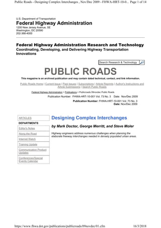
- 10. straightforward exercise. However, lane balance also can be achieved through the dedicated lane style with the application of an auxiliary lane on approach to the divergence. In complex conditions, signing for an optional lane may be confusing to drivers and fail to positively communicate the presence of an optional lane. Overhead guide signs, especially the long truss signs with multiple panels that extend across all lanes, need to clearly convey which is the optional lane. In some cases where down arrows are not properly aligned with their respective lanes, drivers might have difficulty differentiating the optional lane. The sign design should be congruent with the motorist's three-dimensional view from behind the wheel. The lane that the driver is in, or lane perspective, also can make a significant difference. Horizontal and vertical curvature can add to the difficulty in discerning which arrows belong to which lanes. Because of these challenges, the optional lane may then be underutilized or create a potential safety concern since it can introduce a rapid driver decision point within a limited sight preview distance. The context of the location as well as consideration of the geometry and ability to effectively sign should influence whether an optional lane or dedicated style is used. The MUTCD illustrates signing schemes for major forks with dedicated lanes and an optional lane. In a recent notice of proposed amendment to the MUTCD, FHWA offered a change to the diagrammatic signs for splits with an optional lane. The proposed new design provides an arrow shaft for each lane. The change is based on a recommendation with supporting evidence found in the FHWA Highway Design Handbook for Older Drivers and Pedestrians (FHWA-RD-01-103). Because the MUTCD does not specifically illustrate how to provide effective signing in complex environments, the provisions for guide signing should be applied holistically and systemically rather than individually. Ultimately, sound engineering judgment should be applied with a clear understanding of what the view will be from the driver's perspective. Signing also should be consistent with the pavement markings and the visual foreground and background. The top diagram shows guidance for signing optional lanes from the 2003 edition of the MUTCD. The lower diagram shows a suggested new design for diagrammatic guide signing of optional lanes whereby the number of arrow shafts matches the number of lanes on the roadway at the sign's location, and each arrow is placed directly above the lane to which it applies. Page 10 of 14Public Roads - Designing Complex Interchanges , Nov/Dec 2009 - FHWA-HRT-10... 16/3/2018https://www.fhwa.dot.gov/publications/publicroads/09novdec/01.cfm
- 11. Advance Guide Signing Perhaps the most critical strategy for assisting drivers through complex interchanges is signing placed ahead of the interchange to provide information that prepares drivers to make decisions and maneuvers in advance. Improper or inadequate signing can impair a driver's ability to read and understand critical guidance information because of mental overload and other factors. The results can include delayed decisionmaking, erratic driver behavior, and maneuvering errors at the decision point. Proper placement and use of advance guide signs is just as important as signs displayed at the decision point. Proper placement will enable drivers to execute more gradual lane changes over a longer distance. Signs at the decision point serve to confirm the lane decisions made on the approach. Advance guide signing also must be adequately spaced to give drivers time to read and comprehend the information. Signs with too much detail or spaced too closely can cause information overload. According to a National Cooperative Highway Research Program report, Additional Investigations on Driver Information Overload, the load imposed by a given array of information is not simply a function of the total number of "bits" of information contained in the array. The tasks the driver is engaged in, the roadway situation, and the driver's skill level are essential, interacting factors. Mental overload also depends on driver expectations, experience, and familiarity with the roadway. The presence of interacting traffic, roadway geometry, navigational choice points, and other traffic control devices and information sources also are critical factors that contribute to driver overload. Sign Consistency Sign consistency includes layout technique, legend details, and sign material quality. Achieving consistency within an entire corridor in lane assignment arrows, diagrammatic legends, and even Page 11 of 14Public Roads - Designing Complex Interchanges , Nov/Dec 2009 - FHWA-HRT-10... 16/3/2018https://www.fhwa.dot.gov/publications/publicroads/09novdec/01.cfm
- 12. letter height can reduce the driver's workload. DOTs should even evaluate materials, including retroreflectivity, lighting, and the age and condition of signs, on a corridor basis. Agencies also should position signs where they can communicate with motorists most effectively rather than at the most convenient or least costly locations. Sometimes existing sign trusses and supports are used to minimize costs, even though the location might not be ideal. Other times the condition of the support structure prevents upgrading panels with new and needed information because of the additional weight. Designers and traffic engineers should emphasize proper sign location early in a project life cycle so that if additional costs are incurred, the scope and budget can absorb the added work. In complex conditions, such as at this interchange, the amount of information can overwhelm some drivers. Highway designers should pursue interchange geometry that facilitates using clear, logical, and simple signing that complements driver expectations. Proper selection of control cities and destinations is critical in communicating with drivers unfamiliar with a region. Despite temptations to add local destinations, using AASHTO control cities and destinations is the proper approach. Those cities are nationally recognized destinations that give important directional guidance to almost all drivers and especially to unfamiliar drivers at critical diverge points. Local destinations might be important to local drivers, but they provide little, if any, guidance to unfamiliar drivers and can add to their confusion. For example, when traveling eastbound on I-80 approaching the I-580/I-880 interchange in Oakland, CA, destinations such as Sacramento (I-80), Stockton or Los Angeles (I-580), and San José (I-880) provide better directional guidance for unfamiliar drivers than local California destinations such as Richmond, Walnut Creek, or San Leandro. "An important philosophy of interchange design is that if it cannot be clearly and simply signed, it should not be built," says Shaw of FHWA's Resource Center. Providing draft signing and marking plans with each conceptual geometric alternative can help vet the interstate access proposal. In some cases, this approach has resulted in eliminating alternatives that otherwise would have met nominal AASHTO geometric design criteria but would have resulted in awkward advance guide signing. "The goal for complex interchange locations should be for the geometry and the guide signing to complement each other," says Shaw. Page 12 of 14Public Roads - Designing Complex Interchanges , Nov/Dec 2009 - FHWA-HRT-10... 16/3/2018https://www.fhwa.dot.gov/publications/publicroads/09novdec/01.cfm
- 13. Overhead guide signs such as this multipaneled truss sign at the MacArthur Maze interchange in Oakland, CA, need to make the optional lane clear. A driver traveling in the far right lane might have difficulty discerning the interior optional lanes. Two Techniques for Improved Design The use of design visualization in the decisionmaking process could improve complex interchange projects. Design visualization employs techniques such as computer graphics, driving simulators, and animation to provide a representation of proposed alternatives and their associated impacts. Designers traditionally have used visualization to convey the final design to decisionmakers, stakeholders, and the public. Some transportation agencies are finding new ways to integrate visualization into project development, such as using visualization not just for public involvement, but also in the design phase. The use of road safety audits (RSAs) during the planning and preliminary design also could improve complex interchanges. An RSA is a formal safety performance examination of an existing or future road or intersection, carried out by an independent, multidisciplinary team. The RSA team estimates and reports on potential road safety issues and identifies opportunities for overall safety improvements. Highway engineers do not have to wait until a complex interchange is built and put into operation before doing an RSA. In fact, the greatest benefit of an RSA comes during the planning and early design stages, when the scope, schedule, and budget are able to absorb changes resulting from the review. Since complex interchanges typically involve large scopes and costs, application of RSAs can serve to reduce scope creep and cost overruns, while ensuring that safety is not compromised. Wisconsin performed an RSA during the final design phase of the Marquette Interchange. Even though the design was more than 90 percent complete, an RSA team identified potential safety issues and provided recommendations that could still be implemented at a low cost. Among the recommendations were extending a concrete barrier to prevent undesirable movements across lanes, enhancing advance guide signing in an area of limited weave distance, restricting certain crossroad intersection movements during peak periods, and posting advisory speed signs along some ramp curves. Although the RSA came late in the project, the State agreed that it added value to the final design. Because of this positive experience, WisDOT crafted a policy that encourages performing an RSA on interchange projects much earlier in the design process, allowing for greater flexibility when responding to potential safety issues identified by the RSA team. What Next? First, the transportation community needs to expand knowledge of driver performance as a function of various design configurations and associated signing at complex interchanges. Researchers and Page 13 of 14Public Roads - Designing Complex Interchanges , Nov/Dec 2009 - FHWA-HRT-10... 16/3/2018https://www.fhwa.dot.gov/publications/publicroads/09novdec/01.cfm
- 14. Page Owner: Office of Research, Development, and Technology, Office of Corporate Research, Technology, and Innovation Management Topics: Public Roads, Research,Safety, Infrastructure, Operations, Environment, Policy, Materials, Pavements, Asphalt, Concrete, Bridges Keywords: Public Roads, Research,Safety, Infrastructure, Operations, Environment, Policy, Materials, Pavements, Asphalt, Concrete, Bridges TRT Terms: Public Roads, Research,Safety, Infrastructure, Operations, Environment, Policy, Materials, Pavements, Asphalt, Concrete, Bridges Scheduled Update: Archive - No Update needed This page last modified on 01/31/2017 designers need to evaluate various lane management techniques — such as optional versus dedicated lanes and techniques for ending auxiliary lanes — to better understand operational and safety performance. Researchers also need to clarify and quantify the relationship between speed, the composition of traffic flow, and the frequency and severity of crashes at interchanges with complex geometric designs. Finally, quantifying the relationship between signing and quality of operations is needed. When designing complex interchanges, taking the entire corridor into consideration, not just the interchange itself, can improve the overall safety and efficiency of the regional transportation system. Understand the sum of the parts. Keep in mind that access to the local network might be competing against achievement of regional mobility. Establishing appropriate project goals for balancing conflicting interests is highly recommended. Think in terms of a performance-driven design, not simply a standards-driven design. As designers implement these recommendations, perhaps drivers, in the end, will feel far less uncertainty and distress when driving through a complex interchange. Mark Doctor is a safety and geometric design engineer in the FHWA Resource Center in Atlanta, GA. Since 1988 he has served with FHWA as area engineer in the Florida Division, intelligent transportation systems (ITS) and traffic management engineer in the former FHWA Region 4 office in Atlanta, and field operations and safety-ITS team leader in the Tennessee Division. He has a B.S. in civil engineering from Clemson University and an M.S. in transportation engineering from the University of Florida. George Merritt has been a safety and design engineer at the FHWA Resource Center in Atlanta since 2008, after joining FHWA in 2001. He started his career as a pavement engineer for the Indiana DOT before becoming an assistant area engineer in FHWA's Alabama Division and then a transportation engineer in the Georgia Division. He earned a B.S. in civil engineering from Trine University in Angola, IN. Steve Moler is a public affairs specialist at the FHWA Resource Center in San Francisco, CA. He has been with FHWA since 2001, assisting the agency's field offices and partners with media relations, public relations, and public involvement communications. He has a B.S. in journalism from the University of Colorado at Boulder. The policy of FHWA is to maintain the interstate highway system to provide the highest level of service in terms of safety and mobility. Additional information about FHWA's policy on interstate access (Federal Register February 11, 1998, FR Vol. 63, Number 28, pages 7045-7047) is available at www.fhwa.dot.gov/programadmin/fraccess.cfm. Also contact Mark Doctor at 404-562-3732 or mark.doctor@dot.gov, or George Merritt at 404-562- 3911 or george.merritt@dot.gov, or Steve Moler at 415-744-3103 or steve.moler@dot.gov. Page 14 of 14Public Roads - Designing Complex Interchanges , Nov/Dec 2009 - FHWA-HRT-10... 16/3/2018https://www.fhwa.dot.gov/publications/publicroads/09novdec/01.cfm