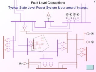
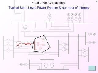
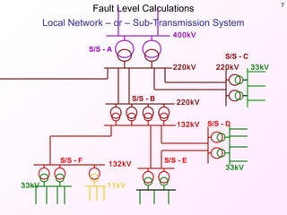
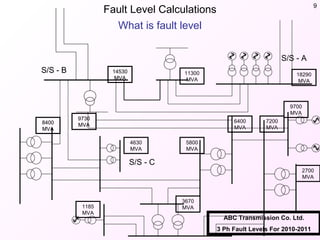
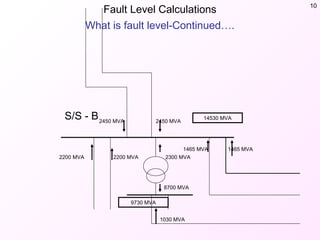
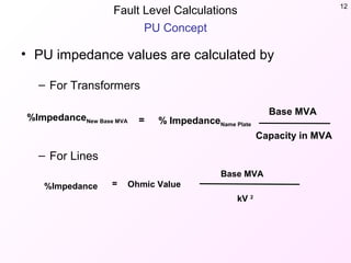
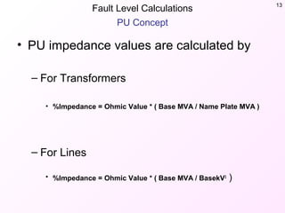
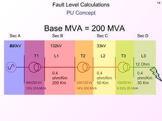
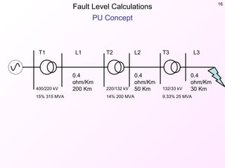
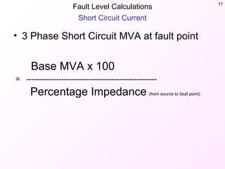
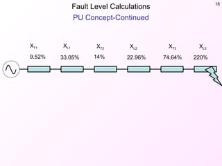
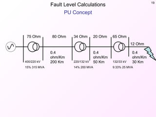
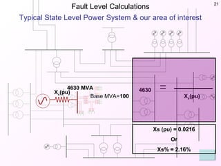
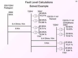
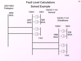
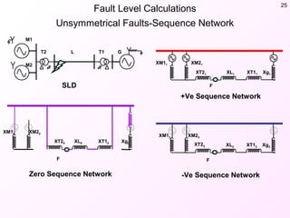
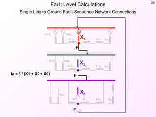
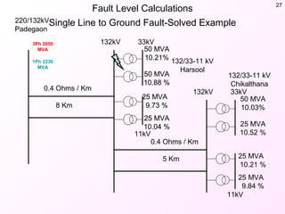
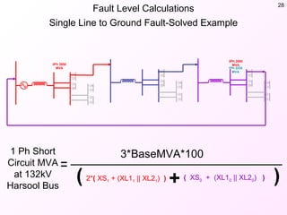
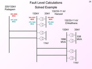
SlideShare a Scribd company logo
1 of 30
Today’s Session
• Fault Level Calculations
– Power-system Overview
– PU Concept
– 3 Ph. Fault Level Calculations
– 1 Ph Fault Level Calculations
• O/C E/F Relay Time Coordination
– General information about relay characteristic
– Worked out example
• Directional Relay
– What is MTA
– How to confirm direction of relay reach while in
service
What is ahead?
Fault Level
Calculations
Fault Level Calculations 3
What is ahead?
• Overview of transmission network.
• What is mean by fault level
• PU Concept
• Network Modeling
• Fault Level Calculation & Worked out
example
– Three Phase Fault
– SLG Fault
Fault Level Calculations 4
Step-1
Overview of power system
grid and transmission
network
Fault Level Calculations 5
Typical State Level Power System & our area of interest
Fault Level Calculations 6
Typical State Level Power System & our area of interest
Fault Level Calculations 7
400kV
220kV
220kV
132kV
33kV
33kV220kV
132kV
11kV33kV
S/S - A
S/S - F S/S - E
S/S - B
S/S - C
S/S - D
Local Network – or – Sub-Transmission System
Fault Level Calculations 8
Step-2
What is mean by fault level
Fault Level Calculations 9
What is fault level
ABC Transmission Co. Ltd.
3 Ph Fault Levels For 2010-2011
14530
MVA
18290
MVA
9700
MVA
8400
MVA
11300
MVA
4630
MVA
5800
MVA
6400
MVA
7200
MVA
2700
MVA
1185
MVA
3670
MVA
9730
MVA
S/S - B
S/S - A
S/S - C
14530
MVA
8400
MVA
9730
MVA
S/S - B
Fault Level Calculations 10
What is fault level-Continued….
14530 MVA
9730 MVA
S/S - B
2200 MVA 2200 MVA 2300 MVA
2450 MVA 2450 MVA
1465 MVA1465 MVA
8700 MVA
1030 MVA
Fault Level Calculations 11
Step-3
Understanding Per-Unit
Measurements
Fault Level Calculations 12
PU Concept
• PU impedance values are calculated by
– For Transformers
– For Lines
%ImpedanceNew Base MVA = % ImpedanceName Plate
Base MVA
Capacity in MVA
%Impedance = Ohmic Value
Base MVA
kV 2
Fault Level Calculations 13
PU Concept
• PU impedance values are calculated by
– For Transformers
• %Impedance = Ohmic Value * ( Base MVA / Name Plate MVA )
– For Lines
• %Impedance = Ohmic Value * ( Base MVA / BasekV2
)
Fault Level Calculations 14
PU Concept
400/220 kV
15% 315 MVA
12 Ohm
Sec DSec CSec B
0.4
ohm/Km
200 Km
0.4
ohm/Km
50 Km220/132 kV
14% 200 MVA
132/33 kV
9.33% 25 MVA
0.4
ohm/Km
30 Km
Sec A
Base MVA = 200 MVA
400kV 33kV132kV220kV
T1 L1 T2 L2 T3 L3
Fault Level Calculations 15
Step-4
Network Modeling
Fault Level Calculations 16
PU Concept
400/220 kV
15% 315 MVA
L3T3L2T2L1T1
0.4
ohm/Km
200 Km
0.4
ohm/Km
50 Km220/132 kV
14% 200 MVA
132/33 kV
9.33% 25 MVA
0.4
ohm/Km
30 Km
Fault Level Calculations 17
Short Circuit Current
• 3 Phase Short Circuit MVA at fault point
Base MVA x 100
= ----------------------------------------------------
Percentage Impedance (from source to fault point)
Fault Level Calculations 18
PU Concept-Continued
9.52% 33.05% 14% 22.96% 74.64% 220%
XT1 XL1 XL2 XL3XT2 XT3
Fault Level Calculations 19
PU Concept
400/220 kV
15% 315 MVA
12 Ohm
65 Ohm20 Ohm34 Ohm80 Ohm75 Ohm
0.4
ohm/Km
200 Km
0.4
ohm/Km
50 Km220/132 kV
14% 200 MVA
132/33 kV
9.33% 25 MVA
0.4
ohm/Km
30 Km
Fault Level Calculations 20
Step-5
Finding Source Impedance,
Worked out Example
Fault Level Calculations 21
Typical State Level Power System & our area of interest
4630
Base MVA=
Xs(pu)
MVA
100 Xs(pu)
4630
Xs (pu) = 0.0216
Or
Xs% = 2.16%
Fault Level Calculations 22
Solved Example
2850
MVA
8 Km
0.4 Ohms / Km
5 Km
0.4 Ohms / Km
50 MVA
10.21%
50 MVA
10.88 %
25 MVA
9.73 %
25 MVA
10.04 %
50 MVA
10.21%
50 MVA
10.88 %
25 MVA
9.73 %
25 MVA
10.04 %
50 MVA
10.03%
25 MVA
10.52 %
25 MVA
10.21 %
25 MVA
9.84 %
220/132kV
Padegaon
132/33-11 kV
Harsool
132/33-11 kV
Chikalthana
132kV 33kV
11kV
132kV 33kV
11kV
Fault Level Calculations 23
Solved Example
2850
MVA
668
MVA
2257
MVA
220/132kV
Padegaon
132/33-11 kV
Harsool
132/33-11 kV
Chikalthana
132kV 33kV
11kV
132kV 33kV
11kV
1998
MVA
538
MVA
Fault Level Calculations 24
Unsymmetrical Faults-Sequence Network
• Up till now we have discussed 3 Phase
faults which are rear. Most of the fault in
power system are single line to ground
faults.
• To find out the short circuit MVA due to
single phase to ground fault it is necessary
to use Sequence Network
• Let us have a closer look of sequence
network
Fault Level Calculations 25
Unsymmetrical Faults-Sequence Network
M1
M2
T2 L GT1
Xg1XT11XL1XT21
XM21XM11
Xg2XT12XL2
XT22
XM22XM12
Xg0XT10XL0XT20
XM20XM10
F
FF
SLD
+Ve Sequence Network
-Ve Sequence NetworkZero Sequence Network
Fault Level Calculations 26
Single Line to Ground Fault-Sequence Network Connections
Xg1XT11XL1XT21
XM21XM11
F
Xg2XT12XL2
XT22
XM22XM12
F
Xg0XT10XL0XT20
XM20
F
X1
X2
X0
Ia = 3 / (X1 + X2 + X0)
Fault Level Calculations 27
Single Line to Ground Fault-Solved Example
3Ph 2850
MVA
8 Km
0.4 Ohms / Km
5 Km
0.4 Ohms / Km
50 MVA
10.21%
50 MVA
10.88 %
25 MVA
9.73 %
25 MVA
10.04 %
50 MVA
10.21%
50 MVA
10.88 %
25 MVA
9.73 %
25 MVA
10.04 %
50 MVA
10.03%
25 MVA
10.52 %
25 MVA
10.21 %
25 MVA
9.84 %
220/132kV
Padegaon
132/33-11 kV
Harsool
132/33-11 kV
Chikalthana
132kV 33kV
11kV
132kV 33kV
11kV
1Ph 2230
MVA
Fault Level Calculations 28
Single Line to Ground Fault-Solved Example
3Ph 2850
MVA
3Ph 2850
MVA
1Ph 2230
MVA
3*BaseMVA*100
( XS0 + (XL10 || XL20) )2*( XS1 + (XL11 || XL21) )( )+
1 Ph Short
Circuit MVA
at 132kV
Harsool Bus
Fault Level Calculations 29
Solved Example220/132kV
Padegaon
132/33-11 kV
Harsool
132/33-11 kV
Chikalthana
132kV 33kV
11kV
132kV 33kV
11kV
1998
MVA
538
MVA
3Ph 2850
MVA
1Ph 2230
MVA
3Ph 2257
MVA
1Ph 1662
MVA
3Ph 668
MVA
1Ph 604
MVA
Fault Level Calculations 30

More Related Content

What's hot

Testing,maintenance&protection
Testing,maintenance&protectionTesting,maintenance&protection
Testing,maintenance&protectionRakesh Joshi
 
Vacuum Circuit Breaker (VCB) Working and Applications | Uses Of VCB
Vacuum Circuit Breaker (VCB) Working and Applications | Uses Of VCB Vacuum Circuit Breaker (VCB) Working and Applications | Uses Of VCB
Vacuum Circuit Breaker (VCB) Working and Applications | Uses Of VCB System Protection
 
Power Quality and Monitoring
Power Quality and MonitoringPower Quality and Monitoring
Power Quality and Monitoringash08031996
 
industrial training on 132 kv substation
industrial training on 132 kv substationindustrial training on 132 kv substation
industrial training on 132 kv substationpk130992
 
132 kv sub-station, power transmission
132 kv sub-station, power transmission132 kv sub-station, power transmission
132 kv sub-station, power transmissionprasantakcs
 
SWITCHYARD EQUIPMENTS & PROTECTION SYSTEMS
SWITCHYARD EQUIPMENTS & PROTECTION SYSTEMSSWITCHYARD EQUIPMENTS & PROTECTION SYSTEMS
SWITCHYARD EQUIPMENTS & PROTECTION SYSTEMSPartha Parida
 
Substations
SubstationsSubstations
Substationsitfakash
 
400/220 kV SCADA controlled gis based TRANSMISSION SUBSTATION
400/220 kV SCADA controlled gis based TRANSMISSION SUBSTATION400/220 kV SCADA controlled gis based TRANSMISSION SUBSTATION
400/220 kV SCADA controlled gis based TRANSMISSION SUBSTATIONPower System Operation
 
Lv switchgear & lv cable sizing
Lv switchgear & lv cable sizingLv switchgear & lv cable sizing
Lv switchgear & lv cable sizingAsif Eqbal
 
Transformer differential protection
Transformer differential protection Transformer differential protection
Transformer differential protection michaeljmack
 
Switchgear Equipment in a Substation
Switchgear Equipment in a SubstationSwitchgear Equipment in a Substation
Switchgear Equipment in a SubstationMd. Atiqur Rahman
 
Switchgear and protection 1
Switchgear and protection 1Switchgear and protection 1
Switchgear and protection 1Md Irshad Ahmad
 
Unit 03 Protective relays
Unit  03 Protective relaysUnit  03 Protective relays
Unit 03 Protective relaysPremanandDesai
 
Insulation coordination
Insulation coordinationInsulation coordination
Insulation coordinationsarunkutti
 
Power system protection topic 1
Power system protection topic 1Power system protection topic 1
Power system protection topic 1Siswoyo Edo
 
Switchyard design overview
Switchyard design overviewSwitchyard design overview
Switchyard design overviewMilind Punj
 

What's hot (20)

IEEE substation design
IEEE substation designIEEE substation design
IEEE substation design
 
Testing,maintenance&protection
Testing,maintenance&protectionTesting,maintenance&protection
Testing,maintenance&protection
 
Vacuum Circuit Breaker (VCB) Working and Applications | Uses Of VCB
Vacuum Circuit Breaker (VCB) Working and Applications | Uses Of VCB Vacuum Circuit Breaker (VCB) Working and Applications | Uses Of VCB
Vacuum Circuit Breaker (VCB) Working and Applications | Uses Of VCB
 
Motor Protection
Motor ProtectionMotor Protection
Motor Protection
 
Substation
SubstationSubstation
Substation
 
Power Quality and Monitoring
Power Quality and MonitoringPower Quality and Monitoring
Power Quality and Monitoring
 
industrial training on 132 kv substation
industrial training on 132 kv substationindustrial training on 132 kv substation
industrial training on 132 kv substation
 
132 kv sub-station, power transmission
132 kv sub-station, power transmission132 kv sub-station, power transmission
132 kv sub-station, power transmission
 
SWITCHYARD EQUIPMENTS & PROTECTION SYSTEMS
SWITCHYARD EQUIPMENTS & PROTECTION SYSTEMSSWITCHYARD EQUIPMENTS & PROTECTION SYSTEMS
SWITCHYARD EQUIPMENTS & PROTECTION SYSTEMS
 
Substations
SubstationsSubstations
Substations
 
400/220 kV SCADA controlled gis based TRANSMISSION SUBSTATION
400/220 kV SCADA controlled gis based TRANSMISSION SUBSTATION400/220 kV SCADA controlled gis based TRANSMISSION SUBSTATION
400/220 kV SCADA controlled gis based TRANSMISSION SUBSTATION
 
Lv switchgear & lv cable sizing
Lv switchgear & lv cable sizingLv switchgear & lv cable sizing
Lv switchgear & lv cable sizing
 
Transformer differential protection
Transformer differential protection Transformer differential protection
Transformer differential protection
 
Switchgear Equipment in a Substation
Switchgear Equipment in a SubstationSwitchgear Equipment in a Substation
Switchgear Equipment in a Substation
 
Switchgear and protection 1
Switchgear and protection 1Switchgear and protection 1
Switchgear and protection 1
 
Unit 03 Protective relays
Unit  03 Protective relaysUnit  03 Protective relays
Unit 03 Protective relays
 
132kV GSS ppt
132kV GSS ppt132kV GSS ppt
132kV GSS ppt
 
Insulation coordination
Insulation coordinationInsulation coordination
Insulation coordination
 
Power system protection topic 1
Power system protection topic 1Power system protection topic 1
Power system protection topic 1
 
Switchyard design overview
Switchyard design overviewSwitchyard design overview
Switchyard design overview
 

Similar to Fault level calculations

Modelling of 25 kV Electric Railway System
Modelling of 25 kV Electric Railway SystemModelling of 25 kV Electric Railway System
Modelling of 25 kV Electric Railway SystemBérengère VIGNAUX
 
UNDERGROUND CABLE FAULT DISTANCE LOCATOR
UNDERGROUND CABLE FAULT DISTANCE LOCATORUNDERGROUND CABLE FAULT DISTANCE LOCATOR
UNDERGROUND CABLE FAULT DISTANCE LOCATORijiert bestjournal
 
Cahpter_7_Symmetrical_Fault_Analysis.pptx
Cahpter_7_Symmetrical_Fault_Analysis.pptxCahpter_7_Symmetrical_Fault_Analysis.pptx
Cahpter_7_Symmetrical_Fault_Analysis.pptxAbhishekRanjan17318
 
fall00_boone.ppt
fall00_boone.pptfall00_boone.ppt
fall00_boone.pptMarcWorld
 
Voltage Profile Improvement using Switched Capacitors: Case of Single Wire Ea...
Voltage Profile Improvement using Switched Capacitors: Case of Single Wire Ea...Voltage Profile Improvement using Switched Capacitors: Case of Single Wire Ea...
Voltage Profile Improvement using Switched Capacitors: Case of Single Wire Ea...IJMERJOURNAL
 
1660034363151685.pptx
1660034363151685.pptx1660034363151685.pptx
1660034363151685.pptxPradip khatri
 
Rehabilitation of nablus electrical network by adding a new connection point
Rehabilitation of nablus electrical network by adding a new connection pointRehabilitation of nablus electrical network by adding a new connection point
Rehabilitation of nablus electrical network by adding a new connection pointslmnsvn
 
Switching Over Voltages (SOV)_Temporary Over Voltage (TOV).pdf
Switching Over Voltages (SOV)_Temporary Over Voltage (TOV).pdfSwitching Over Voltages (SOV)_Temporary Over Voltage (TOV).pdf
Switching Over Voltages (SOV)_Temporary Over Voltage (TOV).pdfssuserfe5963
 
Partial discharge monitoring of High Voltage Assets - TATA Steel Scunthorpe
Partial discharge monitoring of High Voltage Assets - TATA Steel Scunthorpe Partial discharge monitoring of High Voltage Assets - TATA Steel Scunthorpe
Partial discharge monitoring of High Voltage Assets - TATA Steel Scunthorpe Mikolaj Kukawski
 
ECNG 3015 - PU system and 3Phase Fault calculation
ECNG 3015 - PU system and 3Phase Fault calculation ECNG 3015 - PU system and 3Phase Fault calculation
ECNG 3015 - PU system and 3Phase Fault calculation Chandrabhan Sharma
 
Power transformers rating
Power transformers ratingPower transformers rating
Power transformers ratingLeonardo ENERGY
 
45 16255 ee543_2015_1__2_1_week_1_2
45 16255 ee543_2015_1__2_1_week_1_245 16255 ee543_2015_1__2_1_week_1_2
45 16255 ee543_2015_1__2_1_week_1_2Durga Prasada Rao M
 
EXPERIMENTAL DETERMINATION AND ANALYSIS OF TRANSMISSION LINE PERFORMANCE
EXPERIMENTAL DETERMINATION AND ANALYSIS OF TRANSMISSION LINE PERFORMANCEEXPERIMENTAL DETERMINATION AND ANALYSIS OF TRANSMISSION LINE PERFORMANCE
EXPERIMENTAL DETERMINATION AND ANALYSIS OF TRANSMISSION LINE PERFORMANCEijiert bestjournal
 
BASIC ELECTRO MECHANICAL ARRANGEMENTS.pptx
BASIC ELECTRO MECHANICAL ARRANGEMENTS.pptxBASIC ELECTRO MECHANICAL ARRANGEMENTS.pptx
BASIC ELECTRO MECHANICAL ARRANGEMENTS.pptxVenkataLokeshMamidis
 

Similar to Fault level calculations (20)

Dc and ac fundamentals
Dc and ac fundamentalsDc and ac fundamentals
Dc and ac fundamentals
 
Modelling of 25 kV Electric Railway System
Modelling of 25 kV Electric Railway SystemModelling of 25 kV Electric Railway System
Modelling of 25 kV Electric Railway System
 
UNDERGROUND CABLE FAULT DISTANCE LOCATOR
UNDERGROUND CABLE FAULT DISTANCE LOCATORUNDERGROUND CABLE FAULT DISTANCE LOCATOR
UNDERGROUND CABLE FAULT DISTANCE LOCATOR
 
Cahpter_7_Symmetrical_Fault_Analysis.pptx
Cahpter_7_Symmetrical_Fault_Analysis.pptxCahpter_7_Symmetrical_Fault_Analysis.pptx
Cahpter_7_Symmetrical_Fault_Analysis.pptx
 
fall00_boone.ppt
fall00_boone.pptfall00_boone.ppt
fall00_boone.ppt
 
Voltage Profile Improvement using Switched Capacitors: Case of Single Wire Ea...
Voltage Profile Improvement using Switched Capacitors: Case of Single Wire Ea...Voltage Profile Improvement using Switched Capacitors: Case of Single Wire Ea...
Voltage Profile Improvement using Switched Capacitors: Case of Single Wire Ea...
 
ESDEMC CDE IEEE Symposium 2014
ESDEMC CDE IEEE Symposium 2014ESDEMC CDE IEEE Symposium 2014
ESDEMC CDE IEEE Symposium 2014
 
1660034363151685.pptx
1660034363151685.pptx1660034363151685.pptx
1660034363151685.pptx
 
Rehabilitation of nablus electrical network by adding a new connection point
Rehabilitation of nablus electrical network by adding a new connection pointRehabilitation of nablus electrical network by adding a new connection point
Rehabilitation of nablus electrical network by adding a new connection point
 
Switching Over Voltages (SOV)_Temporary Over Voltage (TOV).pdf
Switching Over Voltages (SOV)_Temporary Over Voltage (TOV).pdfSwitching Over Voltages (SOV)_Temporary Over Voltage (TOV).pdf
Switching Over Voltages (SOV)_Temporary Over Voltage (TOV).pdf
 
Partial discharge monitoring of High Voltage Assets - TATA Steel Scunthorpe
Partial discharge monitoring of High Voltage Assets - TATA Steel Scunthorpe Partial discharge monitoring of High Voltage Assets - TATA Steel Scunthorpe
Partial discharge monitoring of High Voltage Assets - TATA Steel Scunthorpe
 
EIT_Presentation
EIT_PresentationEIT_Presentation
EIT_Presentation
 
4771_doc_1
4771_doc_14771_doc_1
4771_doc_1
 
ECNG 3015 - PU system and 3Phase Fault calculation
ECNG 3015 - PU system and 3Phase Fault calculation ECNG 3015 - PU system and 3Phase Fault calculation
ECNG 3015 - PU system and 3Phase Fault calculation
 
Power transformers rating
Power transformers ratingPower transformers rating
Power transformers rating
 
B1102030610
B1102030610B1102030610
B1102030610
 
45 16255 ee543_2015_1__2_1_week_1_2
45 16255 ee543_2015_1__2_1_week_1_245 16255 ee543_2015_1__2_1_week_1_2
45 16255 ee543_2015_1__2_1_week_1_2
 
EXPERIMENTAL DETERMINATION AND ANALYSIS OF TRANSMISSION LINE PERFORMANCE
EXPERIMENTAL DETERMINATION AND ANALYSIS OF TRANSMISSION LINE PERFORMANCEEXPERIMENTAL DETERMINATION AND ANALYSIS OF TRANSMISSION LINE PERFORMANCE
EXPERIMENTAL DETERMINATION AND ANALYSIS OF TRANSMISSION LINE PERFORMANCE
 
BASIC ELECTRO MECHANICAL ARRANGEMENTS.pptx
BASIC ELECTRO MECHANICAL ARRANGEMENTS.pptxBASIC ELECTRO MECHANICAL ARRANGEMENTS.pptx
BASIC ELECTRO MECHANICAL ARRANGEMENTS.pptx
 
Moizuddin_Mohammed
Moizuddin_MohammedMoizuddin_Mohammed
Moizuddin_Mohammed
 

Recently uploaded

CCS355 Neural Networks & Deep Learning Unit 1 PDF notes with Question bank .pdf
CCS355 Neural Networks & Deep Learning Unit 1 PDF notes with Question bank .pdfCCS355 Neural Networks & Deep Learning Unit 1 PDF notes with Question bank .pdf
CCS355 Neural Networks & Deep Learning Unit 1 PDF notes with Question bank .pdfAsst.prof M.Gokilavani
 
IVE Industry Focused Event - Defence Sector 2024
IVE Industry Focused Event - Defence Sector 2024IVE Industry Focused Event - Defence Sector 2024
IVE Industry Focused Event - Defence Sector 2024Mark Billinghurst
 
Internship report on mechanical engineering
Internship report on mechanical engineeringInternship report on mechanical engineering
Internship report on mechanical engineeringmalavadedarshan25
 
Application of Residue Theorem to evaluate real integrations.pptx
Application of Residue Theorem to evaluate real integrations.pptxApplication of Residue Theorem to evaluate real integrations.pptx
Application of Residue Theorem to evaluate real integrations.pptx959SahilShah
 
Call Girls Narol 7397865700 Independent Call Girls
Call Girls Narol 7397865700 Independent Call GirlsCall Girls Narol 7397865700 Independent Call Girls
Call Girls Narol 7397865700 Independent Call Girlsssuser7cb4ff
 
Artificial-Intelligence-in-Electronics (K).pptx
Artificial-Intelligence-in-Electronics (K).pptxArtificial-Intelligence-in-Electronics (K).pptx
Artificial-Intelligence-in-Electronics (K).pptxbritheesh05
 
Introduction-To-Agricultural-Surveillance-Rover.pptx
Introduction-To-Agricultural-Surveillance-Rover.pptxIntroduction-To-Agricultural-Surveillance-Rover.pptx
Introduction-To-Agricultural-Surveillance-Rover.pptxk795866
 
Sachpazis Costas: Geotechnical Engineering: A student's Perspective Introduction
Sachpazis Costas: Geotechnical Engineering: A student's Perspective IntroductionSachpazis Costas: Geotechnical Engineering: A student's Perspective Introduction
Sachpazis Costas: Geotechnical Engineering: A student's Perspective IntroductionDr.Costas Sachpazis
 
Decoding Kotlin - Your guide to solving the mysterious in Kotlin.pptx
Decoding Kotlin - Your guide to solving the mysterious in Kotlin.pptxDecoding Kotlin - Your guide to solving the mysterious in Kotlin.pptx
Decoding Kotlin - Your guide to solving the mysterious in Kotlin.pptxJoão Esperancinha
 
Heart Disease Prediction using machine learning.pptx
Heart Disease Prediction using machine learning.pptxHeart Disease Prediction using machine learning.pptx
Heart Disease Prediction using machine learning.pptxPoojaBan
 
VICTOR MAESTRE RAMIREZ - Planetary Defender on NASA's Double Asteroid Redirec...
VICTOR MAESTRE RAMIREZ - Planetary Defender on NASA's Double Asteroid Redirec...VICTOR MAESTRE RAMIREZ - Planetary Defender on NASA's Double Asteroid Redirec...
VICTOR MAESTRE RAMIREZ - Planetary Defender on NASA's Double Asteroid Redirec...VICTOR MAESTRE RAMIREZ
 
Architect Hassan Khalil Portfolio for 2024
Architect Hassan Khalil Portfolio for 2024Architect Hassan Khalil Portfolio for 2024
Architect Hassan Khalil Portfolio for 2024hassan khalil
 
Arduino_CSE ece ppt for working and principal of arduino.ppt
Arduino_CSE ece ppt for working and principal of arduino.pptArduino_CSE ece ppt for working and principal of arduino.ppt
Arduino_CSE ece ppt for working and principal of arduino.pptSAURABHKUMAR892774
 
Biology for Computer Engineers Course Handout.pptx
Biology for Computer Engineers Course Handout.pptxBiology for Computer Engineers Course Handout.pptx
Biology for Computer Engineers Course Handout.pptxDeepakSakkari2
 
Effects of rheological properties on mixing
Effects of rheological properties on mixingEffects of rheological properties on mixing
Effects of rheological properties on mixingviprabot1
 
Software and Systems Engineering Standards: Verification and Validation of Sy...
Software and Systems Engineering Standards: Verification and Validation of Sy...Software and Systems Engineering Standards: Verification and Validation of Sy...
Software and Systems Engineering Standards: Verification and Validation of Sy...VICTOR MAESTRE RAMIREZ
 

Recently uploaded (20)

Call Us -/9953056974- Call Girls In Vikaspuri-/- Delhi NCR
Call Us -/9953056974- Call Girls In Vikaspuri-/- Delhi NCRCall Us -/9953056974- Call Girls In Vikaspuri-/- Delhi NCR
Call Us -/9953056974- Call Girls In Vikaspuri-/- Delhi NCR
 
CCS355 Neural Networks & Deep Learning Unit 1 PDF notes with Question bank .pdf
CCS355 Neural Networks & Deep Learning Unit 1 PDF notes with Question bank .pdfCCS355 Neural Networks & Deep Learning Unit 1 PDF notes with Question bank .pdf
CCS355 Neural Networks & Deep Learning Unit 1 PDF notes with Question bank .pdf
 
IVE Industry Focused Event - Defence Sector 2024
IVE Industry Focused Event - Defence Sector 2024IVE Industry Focused Event - Defence Sector 2024
IVE Industry Focused Event - Defence Sector 2024
 
Internship report on mechanical engineering
Internship report on mechanical engineeringInternship report on mechanical engineering
Internship report on mechanical engineering
 
Application of Residue Theorem to evaluate real integrations.pptx
Application of Residue Theorem to evaluate real integrations.pptxApplication of Residue Theorem to evaluate real integrations.pptx
Application of Residue Theorem to evaluate real integrations.pptx
 
Call Girls Narol 7397865700 Independent Call Girls
Call Girls Narol 7397865700 Independent Call GirlsCall Girls Narol 7397865700 Independent Call Girls
Call Girls Narol 7397865700 Independent Call Girls
 
Artificial-Intelligence-in-Electronics (K).pptx
Artificial-Intelligence-in-Electronics (K).pptxArtificial-Intelligence-in-Electronics (K).pptx
Artificial-Intelligence-in-Electronics (K).pptx
 
Introduction-To-Agricultural-Surveillance-Rover.pptx
Introduction-To-Agricultural-Surveillance-Rover.pptxIntroduction-To-Agricultural-Surveillance-Rover.pptx
Introduction-To-Agricultural-Surveillance-Rover.pptx
 
young call girls in Rajiv Chowk🔝 9953056974 🔝 Delhi escort Service
young call girls in Rajiv Chowk🔝 9953056974 🔝 Delhi escort Serviceyoung call girls in Rajiv Chowk🔝 9953056974 🔝 Delhi escort Service
young call girls in Rajiv Chowk🔝 9953056974 🔝 Delhi escort Service
 
Sachpazis Costas: Geotechnical Engineering: A student's Perspective Introduction
Sachpazis Costas: Geotechnical Engineering: A student's Perspective IntroductionSachpazis Costas: Geotechnical Engineering: A student's Perspective Introduction
Sachpazis Costas: Geotechnical Engineering: A student's Perspective Introduction
 
Decoding Kotlin - Your guide to solving the mysterious in Kotlin.pptx
Decoding Kotlin - Your guide to solving the mysterious in Kotlin.pptxDecoding Kotlin - Your guide to solving the mysterious in Kotlin.pptx
Decoding Kotlin - Your guide to solving the mysterious in Kotlin.pptx
 
Heart Disease Prediction using machine learning.pptx
Heart Disease Prediction using machine learning.pptxHeart Disease Prediction using machine learning.pptx
Heart Disease Prediction using machine learning.pptx
 
VICTOR MAESTRE RAMIREZ - Planetary Defender on NASA's Double Asteroid Redirec...
VICTOR MAESTRE RAMIREZ - Planetary Defender on NASA's Double Asteroid Redirec...VICTOR MAESTRE RAMIREZ - Planetary Defender on NASA's Double Asteroid Redirec...
VICTOR MAESTRE RAMIREZ - Planetary Defender on NASA's Double Asteroid Redirec...
 
young call girls in Green Park🔝 9953056974 🔝 escort Service
young call girls in Green Park🔝 9953056974 🔝 escort Serviceyoung call girls in Green Park🔝 9953056974 🔝 escort Service
young call girls in Green Park🔝 9953056974 🔝 escort Service
 
Design and analysis of solar grass cutter.pdf
Design and analysis of solar grass cutter.pdfDesign and analysis of solar grass cutter.pdf
Design and analysis of solar grass cutter.pdf
 
Architect Hassan Khalil Portfolio for 2024
Architect Hassan Khalil Portfolio for 2024Architect Hassan Khalil Portfolio for 2024
Architect Hassan Khalil Portfolio for 2024
 
Arduino_CSE ece ppt for working and principal of arduino.ppt
Arduino_CSE ece ppt for working and principal of arduino.pptArduino_CSE ece ppt for working and principal of arduino.ppt
Arduino_CSE ece ppt for working and principal of arduino.ppt
 
Biology for Computer Engineers Course Handout.pptx
Biology for Computer Engineers Course Handout.pptxBiology for Computer Engineers Course Handout.pptx
Biology for Computer Engineers Course Handout.pptx
 
Effects of rheological properties on mixing
Effects of rheological properties on mixingEffects of rheological properties on mixing
Effects of rheological properties on mixing
 
Software and Systems Engineering Standards: Verification and Validation of Sy...
Software and Systems Engineering Standards: Verification and Validation of Sy...Software and Systems Engineering Standards: Verification and Validation of Sy...
Software and Systems Engineering Standards: Verification and Validation of Sy...
 

Fault level calculations

  • 1. Today’s Session • Fault Level Calculations – Power-system Overview – PU Concept – 3 Ph. Fault Level Calculations – 1 Ph Fault Level Calculations • O/C E/F Relay Time Coordination – General information about relay characteristic – Worked out example • Directional Relay – What is MTA – How to confirm direction of relay reach while in service What is ahead?
  • 3. Fault Level Calculations 3 What is ahead? • Overview of transmission network. • What is mean by fault level • PU Concept • Network Modeling • Fault Level Calculation & Worked out example – Three Phase Fault – SLG Fault
  • 4. Fault Level Calculations 4 Step-1 Overview of power system grid and transmission network
  • 5. Fault Level Calculations 5 Typical State Level Power System & our area of interest
  • 6. Fault Level Calculations 6 Typical State Level Power System & our area of interest
  • 7. Fault Level Calculations 7 400kV 220kV 220kV 132kV 33kV 33kV220kV 132kV 11kV33kV S/S - A S/S - F S/S - E S/S - B S/S - C S/S - D Local Network – or – Sub-Transmission System
  • 8. Fault Level Calculations 8 Step-2 What is mean by fault level
  • 9. Fault Level Calculations 9 What is fault level ABC Transmission Co. Ltd. 3 Ph Fault Levels For 2010-2011 14530 MVA 18290 MVA 9700 MVA 8400 MVA 11300 MVA 4630 MVA 5800 MVA 6400 MVA 7200 MVA 2700 MVA 1185 MVA 3670 MVA 9730 MVA S/S - B S/S - A S/S - C 14530 MVA 8400 MVA 9730 MVA S/S - B
  • 10. Fault Level Calculations 10 What is fault level-Continued…. 14530 MVA 9730 MVA S/S - B 2200 MVA 2200 MVA 2300 MVA 2450 MVA 2450 MVA 1465 MVA1465 MVA 8700 MVA 1030 MVA
  • 11. Fault Level Calculations 11 Step-3 Understanding Per-Unit Measurements
  • 12. Fault Level Calculations 12 PU Concept • PU impedance values are calculated by – For Transformers – For Lines %ImpedanceNew Base MVA = % ImpedanceName Plate Base MVA Capacity in MVA %Impedance = Ohmic Value Base MVA kV 2
  • 13. Fault Level Calculations 13 PU Concept • PU impedance values are calculated by – For Transformers • %Impedance = Ohmic Value * ( Base MVA / Name Plate MVA ) – For Lines • %Impedance = Ohmic Value * ( Base MVA / BasekV2 )
  • 14. Fault Level Calculations 14 PU Concept 400/220 kV 15% 315 MVA 12 Ohm Sec DSec CSec B 0.4 ohm/Km 200 Km 0.4 ohm/Km 50 Km220/132 kV 14% 200 MVA 132/33 kV 9.33% 25 MVA 0.4 ohm/Km 30 Km Sec A Base MVA = 200 MVA 400kV 33kV132kV220kV T1 L1 T2 L2 T3 L3
  • 15. Fault Level Calculations 15 Step-4 Network Modeling
  • 16. Fault Level Calculations 16 PU Concept 400/220 kV 15% 315 MVA L3T3L2T2L1T1 0.4 ohm/Km 200 Km 0.4 ohm/Km 50 Km220/132 kV 14% 200 MVA 132/33 kV 9.33% 25 MVA 0.4 ohm/Km 30 Km
  • 17. Fault Level Calculations 17 Short Circuit Current • 3 Phase Short Circuit MVA at fault point Base MVA x 100 = ---------------------------------------------------- Percentage Impedance (from source to fault point)
  • 18. Fault Level Calculations 18 PU Concept-Continued 9.52% 33.05% 14% 22.96% 74.64% 220% XT1 XL1 XL2 XL3XT2 XT3
  • 19. Fault Level Calculations 19 PU Concept 400/220 kV 15% 315 MVA 12 Ohm 65 Ohm20 Ohm34 Ohm80 Ohm75 Ohm 0.4 ohm/Km 200 Km 0.4 ohm/Km 50 Km220/132 kV 14% 200 MVA 132/33 kV 9.33% 25 MVA 0.4 ohm/Km 30 Km
  • 20. Fault Level Calculations 20 Step-5 Finding Source Impedance, Worked out Example
  • 21. Fault Level Calculations 21 Typical State Level Power System & our area of interest 4630 Base MVA= Xs(pu) MVA 100 Xs(pu) 4630 Xs (pu) = 0.0216 Or Xs% = 2.16%
  • 22. Fault Level Calculations 22 Solved Example 2850 MVA 8 Km 0.4 Ohms / Km 5 Km 0.4 Ohms / Km 50 MVA 10.21% 50 MVA 10.88 % 25 MVA 9.73 % 25 MVA 10.04 % 50 MVA 10.21% 50 MVA 10.88 % 25 MVA 9.73 % 25 MVA 10.04 % 50 MVA 10.03% 25 MVA 10.52 % 25 MVA 10.21 % 25 MVA 9.84 % 220/132kV Padegaon 132/33-11 kV Harsool 132/33-11 kV Chikalthana 132kV 33kV 11kV 132kV 33kV 11kV
  • 23. Fault Level Calculations 23 Solved Example 2850 MVA 668 MVA 2257 MVA 220/132kV Padegaon 132/33-11 kV Harsool 132/33-11 kV Chikalthana 132kV 33kV 11kV 132kV 33kV 11kV 1998 MVA 538 MVA
  • 24. Fault Level Calculations 24 Unsymmetrical Faults-Sequence Network • Up till now we have discussed 3 Phase faults which are rear. Most of the fault in power system are single line to ground faults. • To find out the short circuit MVA due to single phase to ground fault it is necessary to use Sequence Network • Let us have a closer look of sequence network
  • 25. Fault Level Calculations 25 Unsymmetrical Faults-Sequence Network M1 M2 T2 L GT1 Xg1XT11XL1XT21 XM21XM11 Xg2XT12XL2 XT22 XM22XM12 Xg0XT10XL0XT20 XM20XM10 F FF SLD +Ve Sequence Network -Ve Sequence NetworkZero Sequence Network
  • 26. Fault Level Calculations 26 Single Line to Ground Fault-Sequence Network Connections Xg1XT11XL1XT21 XM21XM11 F Xg2XT12XL2 XT22 XM22XM12 F Xg0XT10XL0XT20 XM20 F X1 X2 X0 Ia = 3 / (X1 + X2 + X0)
  • 27. Fault Level Calculations 27 Single Line to Ground Fault-Solved Example 3Ph 2850 MVA 8 Km 0.4 Ohms / Km 5 Km 0.4 Ohms / Km 50 MVA 10.21% 50 MVA 10.88 % 25 MVA 9.73 % 25 MVA 10.04 % 50 MVA 10.21% 50 MVA 10.88 % 25 MVA 9.73 % 25 MVA 10.04 % 50 MVA 10.03% 25 MVA 10.52 % 25 MVA 10.21 % 25 MVA 9.84 % 220/132kV Padegaon 132/33-11 kV Harsool 132/33-11 kV Chikalthana 132kV 33kV 11kV 132kV 33kV 11kV 1Ph 2230 MVA
  • 28. Fault Level Calculations 28 Single Line to Ground Fault-Solved Example 3Ph 2850 MVA 3Ph 2850 MVA 1Ph 2230 MVA 3*BaseMVA*100 ( XS0 + (XL10 || XL20) )2*( XS1 + (XL11 || XL21) )( )+ 1 Ph Short Circuit MVA at 132kV Harsool Bus
  • 29. Fault Level Calculations 29 Solved Example220/132kV Padegaon 132/33-11 kV Harsool 132/33-11 kV Chikalthana 132kV 33kV 11kV 132kV 33kV 11kV 1998 MVA 538 MVA 3Ph 2850 MVA 1Ph 2230 MVA 3Ph 2257 MVA 1Ph 1662 MVA 3Ph 668 MVA 1Ph 604 MVA

Editor's Notes

  1. Typical state level power system is shown here. This power system is consists of Generator, EHV lines, ICTs, Transformer, Distribution Feeders etc, Power generated get injected into the system either at 400kV or at 220kV. We can say that major portion of the power system is of 400kV Grid. (Shown violate) Some portion is of 220kV Grid (Shown brown) Generally most of engineers deals with small portion of the network shown inside. Which we may call as Sub-Transmission network. Majority portion of sub-transmission network is of radial nature. While dealing with such limited portion of the system from fault level calculation point of view we can replace the entire external grid system with a source and a thevinians equivalent impedance.
  2. Here grid is replaced by thevinans equivalent impedance. Or to be more specific, while calculating fault levels we can neglect resistance of the elements Thus this impedance is considered as reactance Then next obvious question is how to determine this equivalent reactance. It is explained afterword. But before to proceed further let us have a closer look at Sub-Transmission network And it is necessary to recall our concepts about pu calculations
  3. Here sub-transmission network enlarged ( and rotated clockwise 900) Though following points are un-important or known it is necessary to have common language while discussing some issues/problems regarding power system. Hence such terminology is reviewed here. S/S voltage levels means highest voltage level at that S/S Hence 400kV S/S – A 200kVS/S – B S/S – C 132kVS/S – D S/S – E S/S – F Sub-Stations are also recognized as 400/220kV or 220/33 kV or 220/132kV or 132/33kV or 132/33-11kV (S/S-F) etc. 400kV and one 220kV line of S/S-A is in grid. S/S-B and S/S-C get supplied through parallel lines. S/S-D and S/S-E are connected in local loop network (S/S-D is having LILO arrangement). S/S-F is of radial nature There may have standby lines too.
  4. We may define fault level as - Fault level at any location is that value of current which is expected to flow upon occurrence of fault considering all other elements in network are in service and all generations are in service and generating their maximum output. FOR FAULT LEVEL STUDY SELECTED LOCATION IS BUS IN THE SYSTEM Every year such calculations are done for the entire network of the company at corporate level using computer programs and results circulated to field offices. Generally these fault levels are expressed in MVA or KA. When expressed in MVA it is also called as Short Circuit MVA. Such a sample result is shown here. Generally while calculating fault levels, two type of faults are considered at every bus in the network (Grid). 3 Phase Fault Single Line to Ground Fault (SLG) Here 3 Ph fault is considered. Fault levels for S/S connected to generation are more (S/S-A). Also fault levels having more lines are more (S/S-B). Fault levels of S/S having higher rating transformers are also more
  5. Let us have a closer look of S/S-B During fault level study not only bus fault levels are given but also contribution of this fault by various elements connected to that bus are also given. Not that arrow marking is not necessary. It is only shown here to get the contribution more clear. Such type of data can be given in SLD form as well as Table form too. However if given in SLD form it is more understandable
  6. ================================================================================ Note :- we are using pu impedance and percentage impedance interchangeably throughout the discussion where Percentage Impedance = Per-Unit Impedance * 100 ================================================================================ While modeling a transmission network for fault level study following points are important. Transmission system (or network) is made up of lines and transformers. Line is characterized by inductance, resistance and line charging capacitance. For small length lines, charging capacitance can be neglected while modeling the transmission system. Small length lines are generally of lower voltage. From transmission point of view that is 132kV and 220kV. While modeling the 400kV line we have to consider line charging capacitance too. For fault level calculations only it is necessary to consider reactive impedance of the line. We can exclude line charging and resistance. Transformer impedances are always expressed in percentage (or PU ). ================================================================================ The per-unit impedance of the transformer is the same regardless of whether it is determined from ohmic values referred to high tension or low tension sides of the transformers. For example consider a 132/33 kV 25 MVA transformer under short circuit test. That means about 3 phase 440 V (i.e. 440/1.732 = 254 V Ph-N) supply is given from 132kV side and 33kV side kept short circuited. This transformer short circuit current at 440 V will be about 3.9 amps. That is its leakage impedance is 254/3.9 = 65.12 Ohms Its PU value (referred to 132kV side) is 65*25/(132*132) = 0.0933 ( or 9.33%) If the leakage reactance had been measured on the low tension side, the value would be 65/16 = 4.0625 ( Where 16 is square of transformation ratio (132/33)2 ) Its PU value (referred to 33kV side) is 4.0625*25/(33*33) = 0.0933 (or 9.33%) same as before Same case is about line modeling where base voltages for the lines connected on HV and LV sides of the transformers shall have same ratio as that of transformation ratio In short while calculating per-unit impedance of the line it’s rated voltage is selected as base voltage and base MVA will be common for entire system.
  7. The per-unit impedance of the transformer is the same regardless of whether it is determined from ohmic values referred to high tension or low tension sides of the transformers. For example consider a 132/33 kV 25 MVA transformer under short circuit test. That means about 3 phase 440 V (i.e. 440/1.732 = 254 V Ph-N) supply is given from 132kV side and 33kV side kept short circuited. This transformer short circuit current at 440 V will be about 3.9 amps. That is its leakage impedance is 254/3.9 = 65.12 Ohms Its PU value (referred to 132kV side) is 65*25/(132*132) = 0.0933 ( or 9.33%) If the leakage reactance had been measured on the low tension side, the value would be 65/16 = 4.0625 ( Where 16 is square of transformation ratio (132/33)2 ) Its PU value (referred to 33kV side) is 4.0625*25/(33*33) = 0.0933 (or 9.33%) same as before Same case is about line modeling where base voltages for the lines connected on HV and LV sides of the transformers shall have same ratio as that of transformation ratio In short while calculating per-unit impedance of the line it’s rated voltage is selected as base voltage and base MVA will be common for entire system.
  8. This will be clear by an example consider a simple system as shown above of 400/220kV T/F 220/132kV Transformer and 132/33kV Transformer. Select base MVA of 200 MVA for entire system. Sectionalize the system as per voltage levels Section A is for 400kV Transformer T1 will get included in this section as pu values of transformer whether referred to primary or secondary are same Section B is for 220kV Transformer T1 and also transformer T2 will get included in this section due to same reason as said above. That means all transformers get overlapped by two sections Similarly section C is for 132kV and section D is for 33kV Select 400kV as base voltage in section A It will be converted into 220kV in section B, 132kV in section C and 33kV in section D =========================================================================== By this way line rated voltage will be base voltage for that line ===========================================================================
  9. Now it is possible to calculate per-unit values of transformer and lines with above said base mva and base kv T1 Percentage Impedance = XT1% = 15*200/315 = 9.52% L1 Percentage Impedance = XL1% = (X/Km)*L*( Base MVA / ( kV2 ) )*100 =0.4*200*(200/(220*220))*100 = 33.05% T2 Percentage Impedance = XT2% = 14% L2 Percentage Impedance = XL2% = 0.4*50*(200/(132*132))*100 = 22.96% T3 Percentage Impedance = XT3% = 9.33 * 200/25 = 74.64% L3 Percentage Impedance = XL3% = 0.4*30*(200/(33*33))*100 = 220.38%
  10. Total percentage impedance up to source 220 + 74.64 + 22.96 + 14 + 33.05 + 9.52 = 374.17% Short circuit MVA = 200*100/374.17 = 53.54 MVA Short Circuit Current = 17.5*53.54 = 936 Amp
  11. Same results we get by considering ohmic values. How ever every time it is necessary to take care of transformation ratio hence pu method is always preferable. More ever when we works with large transmission grid extensive use of matrix is required and there is no alternative to pu values. Still we will calculate same results by ohmic method just to realize simplicity of pu method. 12 ohm referred to 132kV = 12*(4*4) = 192 Ohms ( Where 4 is transformation ratio 132/33kV) L3 + T3 + L2 65 + 192 + 20 = 277 ohms This referred to 220kV = 277*(1.6666*1.6666) = 769 Ohms ( Where 1.6666 is transformation ratio 220/132kV) (L3 + T3 + L2 + T2 + L1) Referred to 220kV = 769 + 34 + 80 = 883 Ohms This referred to 400kV = 883*(1.8181*1.8181) = 2918 Ohms ( Where 1.8181 is transformation ratio 400/220kV) (L3 + T3 + L2 + T2 + L1 + T1) = 2918 + 75 = 2993 Ohms Current at 400kV level = (400000/1.732)/2993 = 77.16 Amp Current at 33kV level = 77.16*400/33 = 935 Amp.
  12. Let us again consider radial part of the part of the power system (Sub-Transmission Network) in which we are interested, Let we know the 3 phase short circuit MVA of the Root Bus. From this we can find out source impedance and from source MVA we can proceed further for calculating short circuit MVA of other busses in the radial Sub-Stations branched from Root Bus. As we have just calculated 3 Phase Fault Level at a bus in the grid = Base MVA / Equivalent Per-Unit Impedance up to source Hence Equivalent Per-Unit Impedance up to source from a bus in the system = Base MVA / 3 Phase Fault Level at that bus For the system under consideration its value is 2.16% which is considerable low as compared to other components pu impedances. Hence in such cases we may neglect it too without hampering further results much more
  13. 3 Ph Fault level calculations Calculate source impedance for 132kV Bus Padegaon from given fault level Consider Base MVA as 100 X1s = 100*100/2850 = 3.51% b) Calculate % impedance of Padegaon-Harsool single circuit XL1 = 0.4*8*(100*100)/(132*132) = 1.84% = XL2 c) Total impedance up to Harsool 132kV Bus = 3.51 + ( 1.84 || 1.84 ) = 3.51 + 1.84/2 = 4.43% d) 3 Phase Fault level at 132kV Harsool = 100*100/4.43 = 2257 MVA e) 132/33 kV 50 MVA Transformer percentage impedances at new base MVA XT1 = 10.21*100/50 = 20.42% XT2 = 10.88*100/50 = 21.76% f) Total impedance from 132kV Harsool S/S up to source X1s= 100*100/2257 = 4.43% g) Total impedance up to Harsool 33kV Bus = X1s + (XT1 || XT2) = 4.43 + ( 20.42 || 21.76) = 14.96% h) Fault level at 33kV Harsool Bus = 100*100/14.96 = 668 MVA Fault level at 132kV Chikalthana Bus XL1 = XL2 = 0.4*5*(100*100/(132*132)) = 1.15% Xeq = 4.43 + 1.15/2 = 5.005 Fault level at 132kV Chikalthana = 100*100/5.005 = 1998 MVA j) Fault level at 33 kV Chikalthana XT1new = 10.03 * 100/50 = 20.06% XT2new = 10.52*100/25 = 42.08 Xeq = 5.005 + ( 20.06 || 42.08 ) = 18.59% Fault Level = 100*100/18.59 = 538 MVA
  14. Like wise fault levels of other busses also can be calculated
  15. Without going into much details of the sequence network concept studied in academic years now we will recall some of them. Consider a SLD of stand alone system where a generator feeding 2 synchronous motor loads through a step up transformer, transmission line and a step down transformer. Let there is a SLG fault at F To find out the value of fault current first we will draw the equivalent sequence networks + Ve sequence network is with a source If all values are expressed in pu this source voltage shall be obviously 1.0 pu Subscript 1 in pu impedances of components stands for +Ve sequence impedances -Ve sequence network is exactly like +Ve sequence network Except there is no voltage source. As generated voltage (behind generator reactance Xg ) is always balance hence –Ve and zero sequence of supply voltage component is zero. Subscript 2 in pu impedances of components stands for -Ve sequence impedances NOTE THE REFERANCE BUS IN THE SEQUENCE NETWORK. It is referred to only that sequence network only. While drawing Zero sequence network special care for earthing provided and transformer winding connections has to be taken. Delta connected side get connected to Zero Bus directly. Where as star side get connected to component against it only if star point is earthed If earthing is done through reactance X , then in zero sequence network it is replaced by 3X For calculating single phase fault current we have to connect these three networks in series as shown in next slide.
  16. After connecting sequence network in series ( with respect to fault point ). it is possible to reduce each sequence network into corresponding equivalent sequence impedance as shown above Here +Ve sequence network caries +Ve sequence current –Ve sequence network caries –Ve sequence current and Zero sequence network caries zero sequence current. Due to series configuration I1 = I2 = I0 And R Ph current involved in fault = I1 + I2 + I0 = 3I1 IR = 3/(X1+X2+X0) Or 1 Phase Short Circuit MVA = 3 * ( Base MVA) / (X1 + X2 + X0) if X is expressed in pu = 3*(BaseMVA)*100/(X1% + X2% + X0%) Note : Positive and negative sequence reactance of network components are equal. Zero sequence reactance for the transformer is same as that of +Ve sequence reactance Zero sequence reactance for line are given in data sheet and it is about 2.5 to 3 times its +Ve sequence reactance
  17. As said previously 3 Phase and 1 Phase fault levels of busses in grid are given by studying the system using computer. With availability of this fault levels and formulae reviewed we can proceed further for calculation of single line to ground fault as below 1 Ph Fault level calculations Calculate positive sequence source impedance for 132kV Bus Padegaon from given fault level as previous Consider Base MVA as 100 X1s = 100*100/2850 = 3.51% b) Now 1 Ph fault level = 3*BaseMVA*100/(X1 + X2 + X0) But X1 = X2 = 3.51% Hence 2230 = 3*100*100/(3.51+3.51+X0) 7.02 + X0 = 30000/2230 X0 = 13.45 – 7.02 X0 = 6.43%
  18. As said previously 3 Phase and 1 Phase fault levels of busses in grid are given by studying the system using computer. With availability of this fault levels and formulae reviewed we can proceed further for calculation of single line to ground fault as below b) Calculate % impedance of Padegaon-Harsool single circuit XL1 = 0.4*8*(100*100)/(132*132) = 1.84% = XL2 Let XL0 = 3*XL1 = 5.52% d) 1 Phase Fault level at 132kV Harsool = 3*100*100/(2*(XS1+(XL1||XL2)) + (XS0+XL0)) = 30000 / ( 2*(3.51 + ( 1.84 || 1.84 )) + ( 6.43 + ( 5.52 || 5.52 )) ) = 30000 / ( 8.86 + 9.19 ) = 30000 / 18.05 = 1662 MVA e) 132/33 kV 50 MVA Transformer percentage impedances at new base MVA XT1 = 10.21*100/50 = 20.42% XT2 = 10.88*100/50 = 21.76% h) 1 Phase Fault level at 33kV Harsool Bus = 30000 / ( 2*( Xs1 + (XL11 || XL21) + ( XT11 || XT21) ) + (Xs0 + (XL10 || XL20) + ( XT10 || XT20) ) ) = 30000 / ( 2*(3.51 + 0.92 + 10.53) + (6.43 + 2.76 + 10.53) ) = 30000 / ( 2*14.96 + 19.72 ) = 30000 / 49.64 = 604MVA Like wise you can proceed
  19. Like wise fault levels of other busses also can be calculated