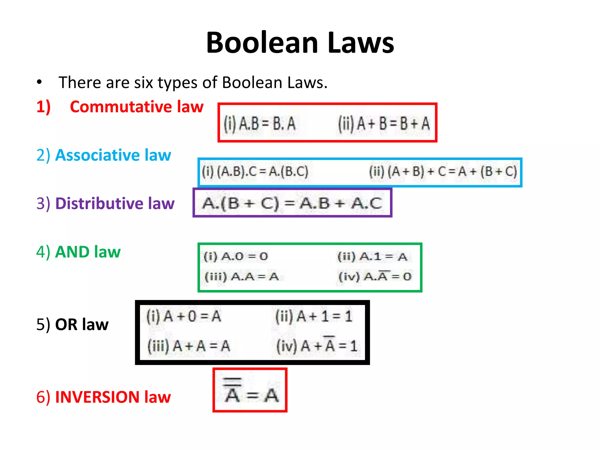
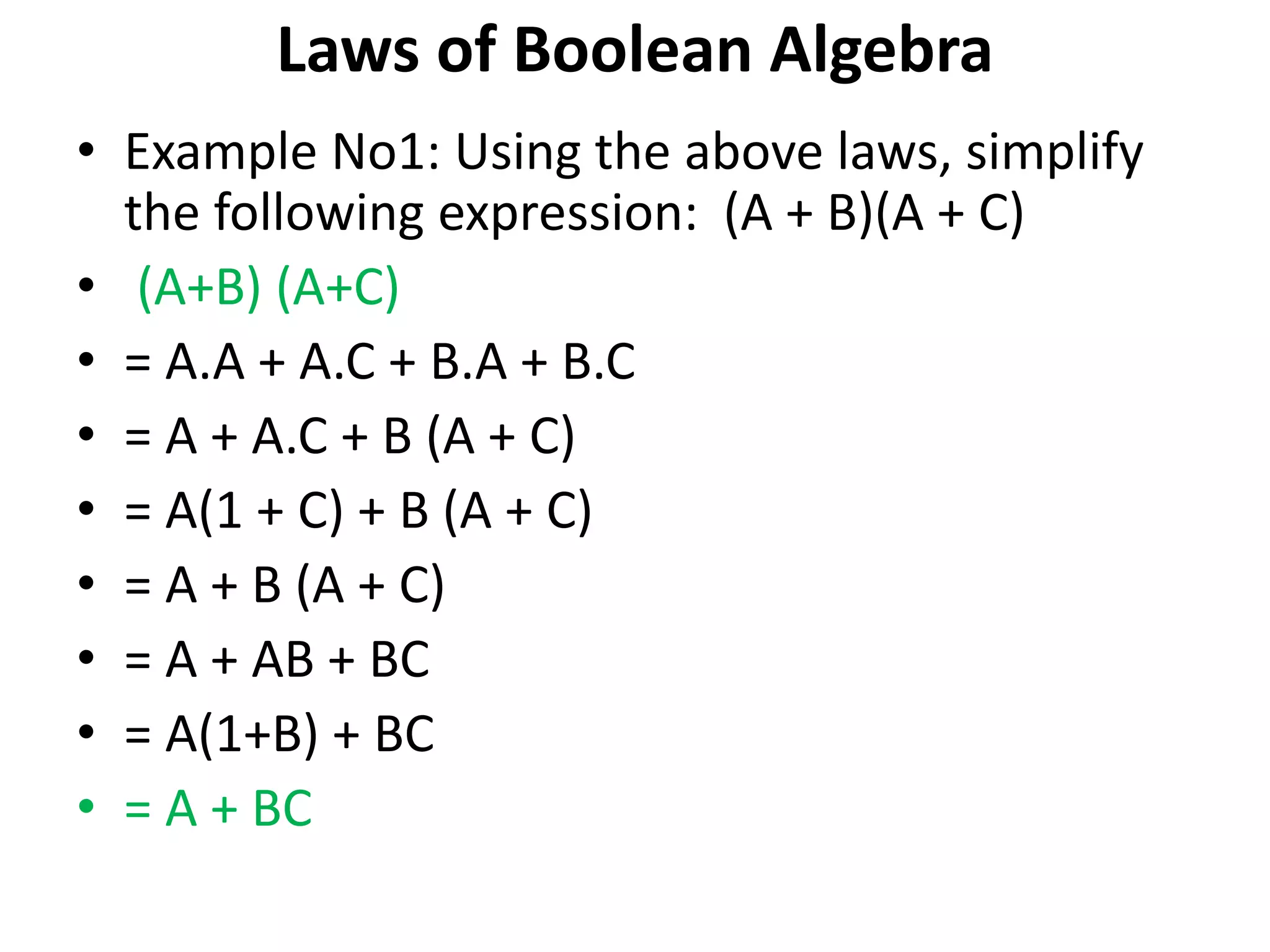
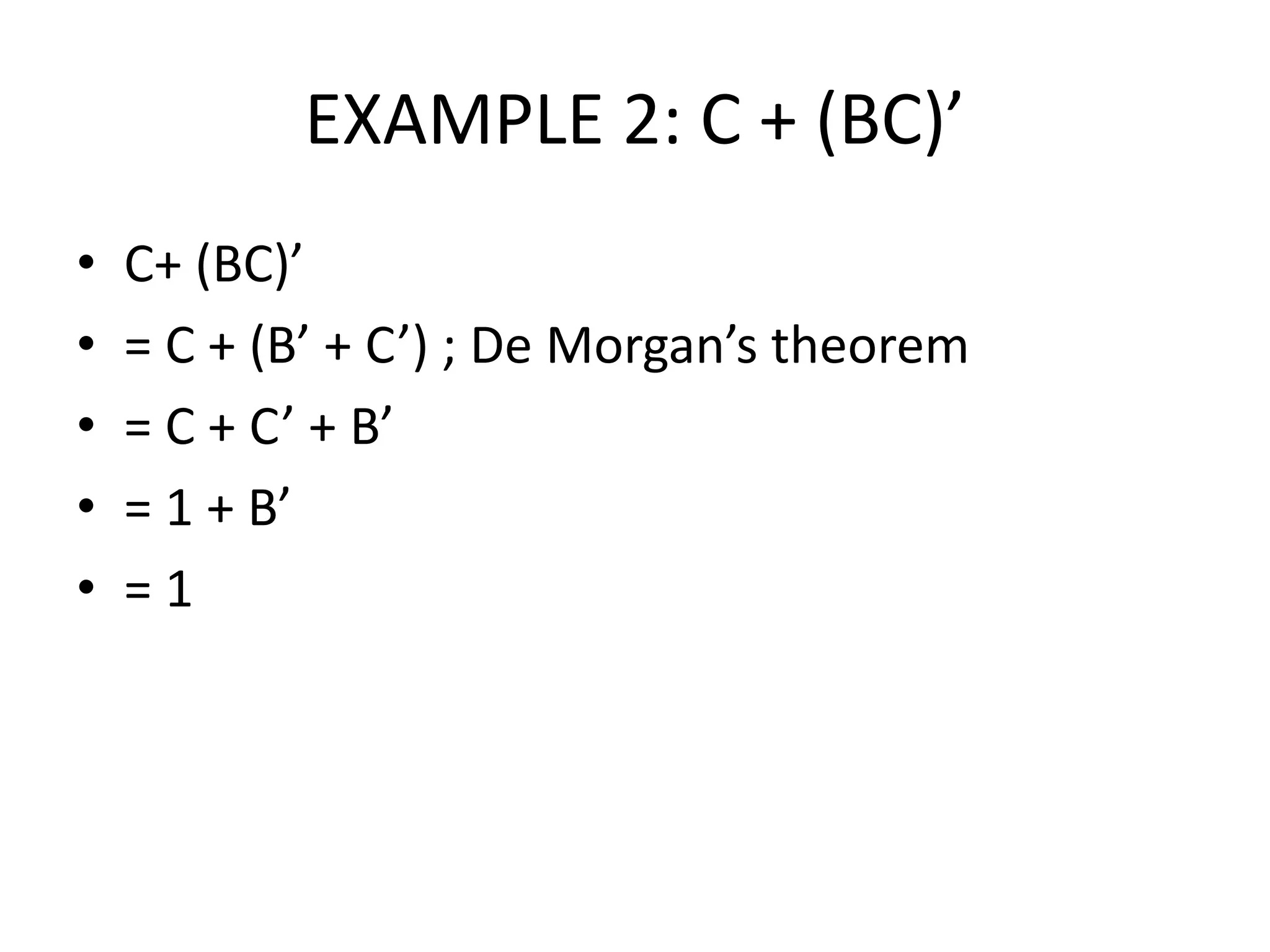
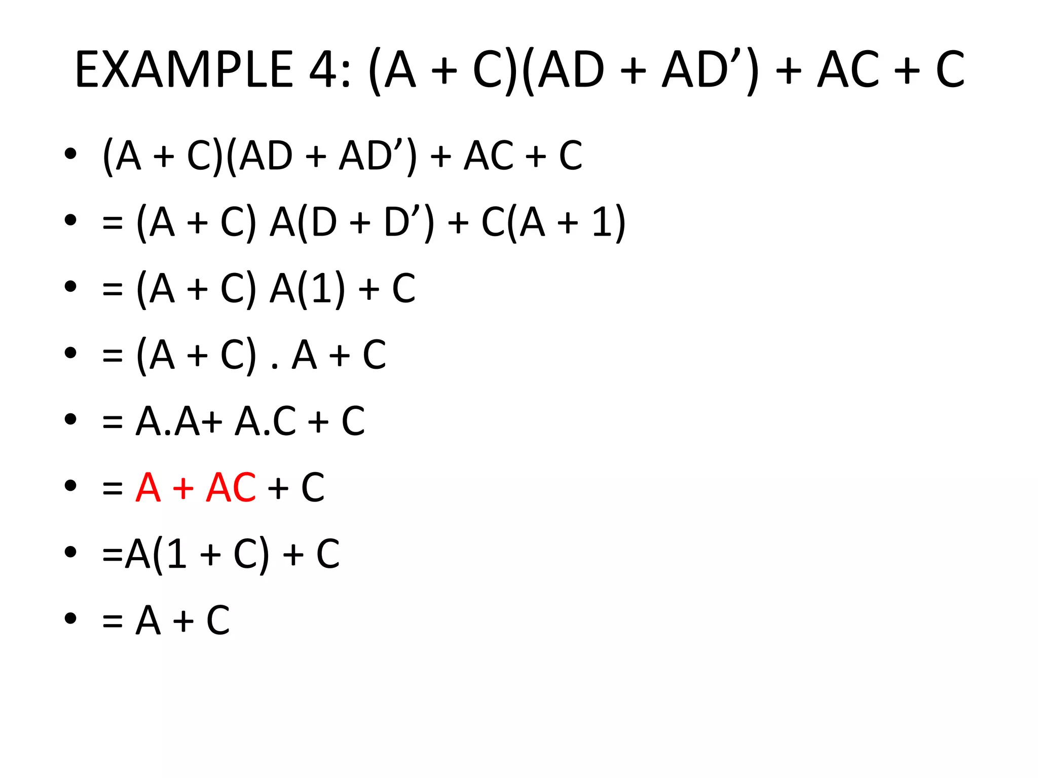
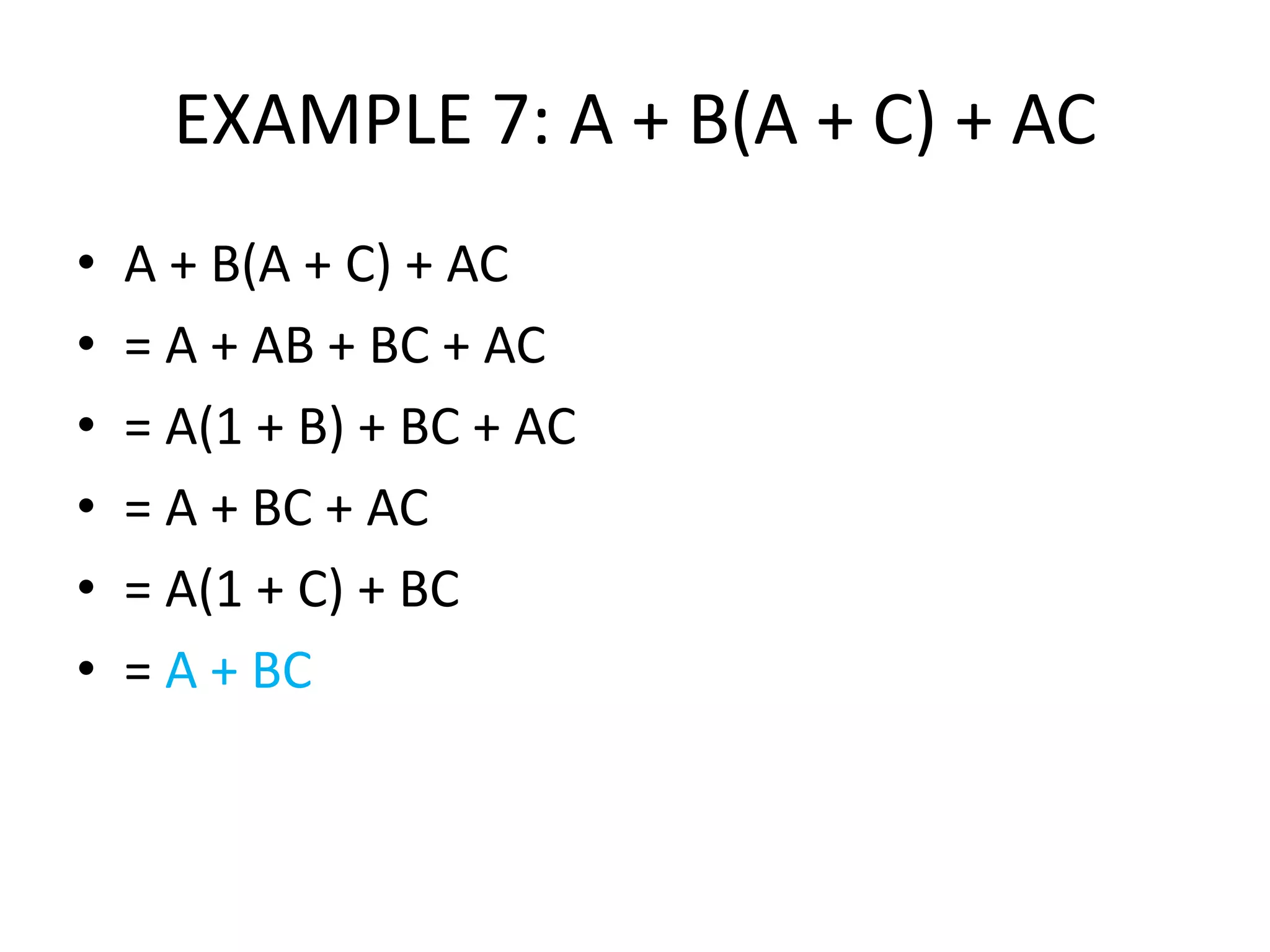
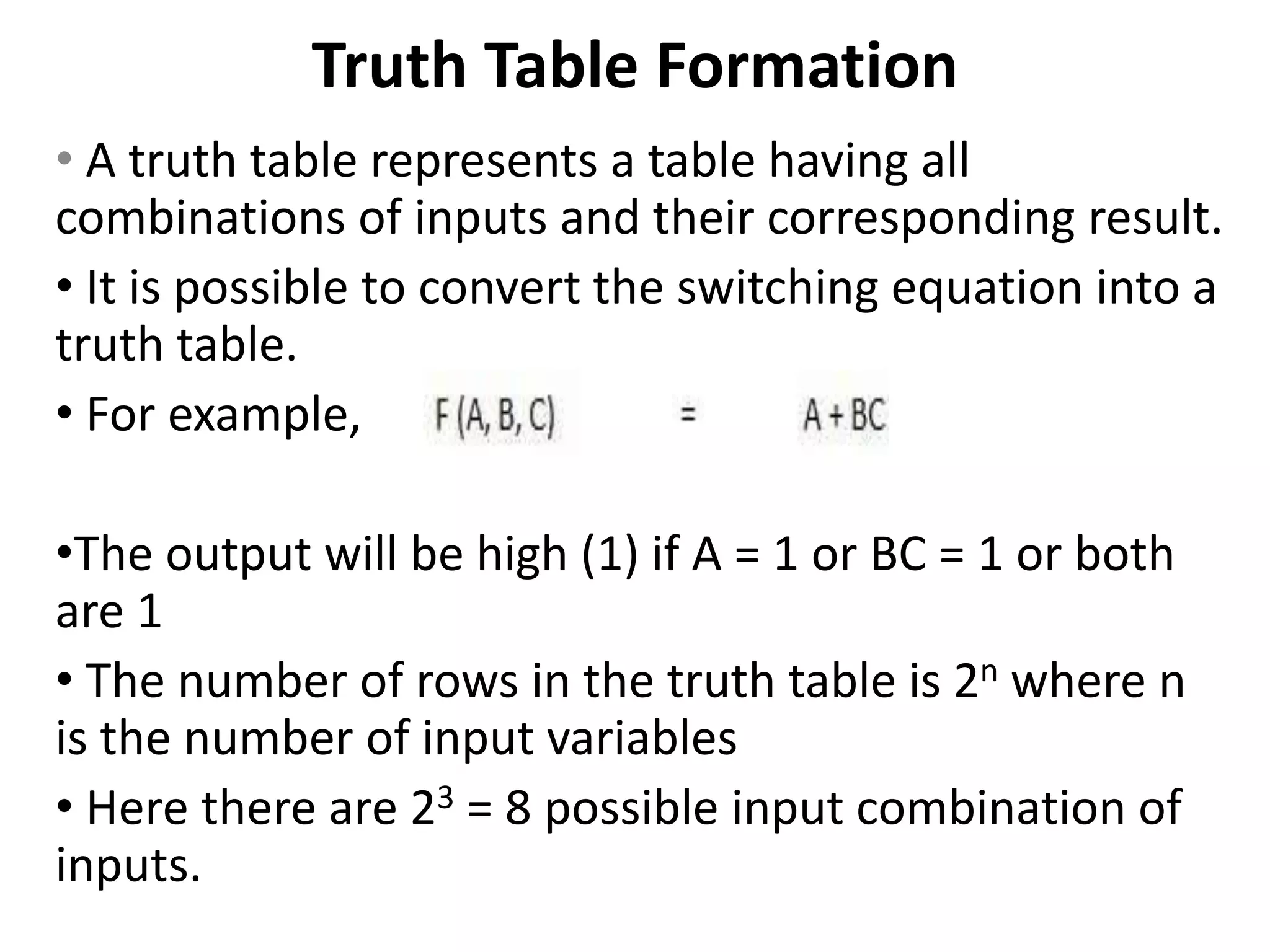
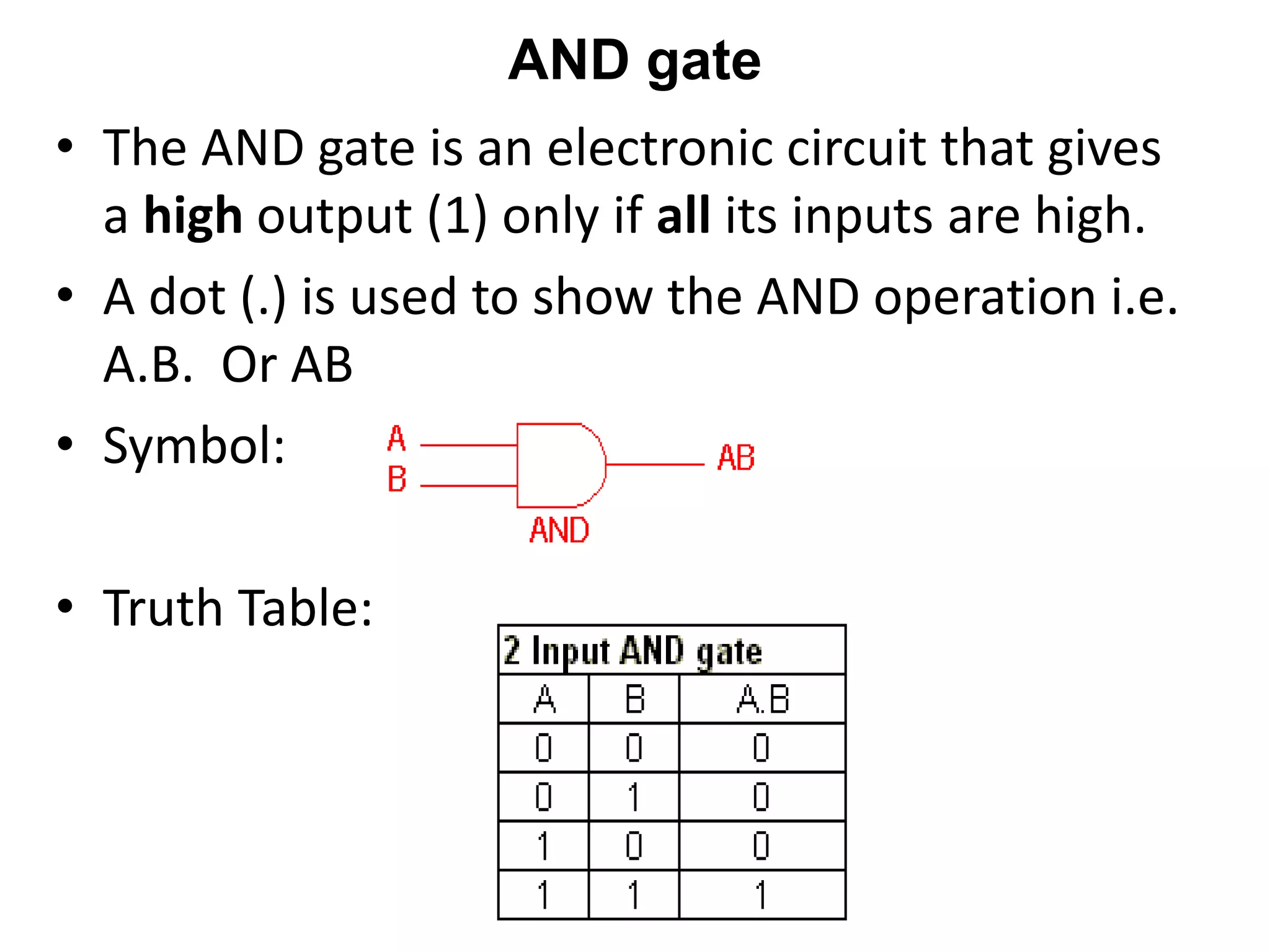
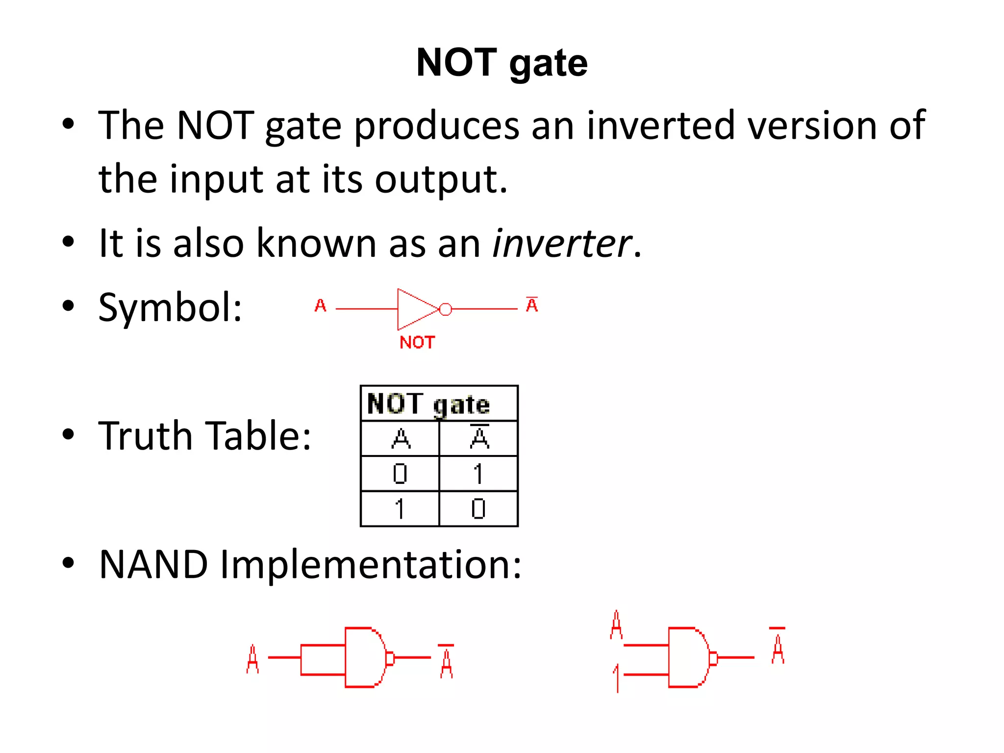
BOOLEAN ALGEBRA
• used to analyze and simplify the digital (logic)
circuits
• uses only the binary numbers i.e. 0 and 1
• called as Binary Algebra or logical Algebra
• invented by George Boole in 1854
Rule in Boolean Algebra
• Variable used can have only two values.
• Binary 1 = HIGH and Binary 0 = LOW.
• Complement of a variable is represented by an
overbar (-)/(‘).
• Thus if B = 0 then B’= 1 and if B = 1 then B’= 0.
• ORing of the variables is represented by a plus (+)
sign between them. Ex- A + B
• Logical ANDing of the two or more variable is
represented by a dot between them. Ex- A.B.C. or
ABC.
Boolean Laws
• There are six types of Boolean Laws.
1) Commutative law
2) Associative law
3) Distributive law
4) AND law
5) OR law
6) INVERSION law
Truth Tables for the Laws of Boolean
Boolean
Expression
Description Equivalent
Switching Circuit
Boolean Algebra
Law or Rule
A + 1 = 1
A in parallel with
closed = “CLOSED” Annulment
A + 0 = A
A in parallel with
open = “A”
Identity
A . 1 = A
A in series with
closed = “A”
Identity
A . 0 = 0
A in series with
open = “OPEN”
Annulment
A + A = A
A in parallel with
A = “A” Idempotent
Boolean
Expression
Description Equivalent
Switching Circuit
Boolean Algebra
Law or Rule
A.B = B.A
A in series with B =
B in series with A
Commutative
(A+B)’ = A’. B’
invert and replace OR
with AND
de Morgan’s Theorem
(A.B)’ = A’ + B’
invert and replace
AND with OR
de Morgan’s Theorem
Laws of Boolean Algebra
• Example No1: Using the above laws, simplify
the following expression: (A + B)(A + C)
• (A+B) (A+C)
• = A.A + A.C + B.A + B.C
• = A + A.C + B (A + C)
• = A(1 + C) + B (A + C)
• = A + B (A + C)
• = A + AB + BC
• = A(1+B) + BC
• = A + BC
EXAMPLE 2: C + (BC)’
• C+ (BC)’
• = C + (B’ + C’) ; De Morgan’s theorem
• = C + C’ + B’
• = 1 + B’
• = 1
EXAMPLE 3: (AB)’(A’ + B)(B’ + B)
• (AB)’(A’ + B)(B’ + B)
• = (A’ + B’) (A’ + B) (1)
• = A’A’ + A’B + A’B’ + B’ B
• = A’ + A’(B + B’) + 0
• = A’ + A’(1)
• = A’ + A’
• = A’
EXAMPLE 4: (A + C)(AD + AD’) + AC + C
• (A + C)(AD + AD’) + AC + C
• = (A + C) A(D + D’) + C(A + 1)
• = (A + C) A(1) + C
• = (A + C) . A + C
• = A.A+ A.C + C
• = A + AC + C
• =A(1 + C) + C
• = A + C
EXAMPLE 5: A’(A + B) + (B + AA)(A + B’)
• A’(A + B) + (B + AA)(A + B’)
• =A’A + A’B + (B + A)(A + B’)
• =0 + A’B + AB + BB’ + AA + AB’
• = B(A’ + A) + 0 + A + AB’
• = B(1) + A( 1 + B’)
• = B + A(1)
• = A + B
EXAMPLE 6: AB + BC(B + C)
• AB + BC(B + C)
• = AB + BBC + BCC
• = AB + BC + BC
• = AB + BC ; BC + BC = BC
• = B(A + C)
EXAMPLE 7: A + B(A + C) + AC
• A + B(A + C) + AC
• = A + AB + BC + AC
• = A(1 + B) + BC + AC
• = A + BC + AC
• = A(1 + C) + BC
• = A + BC
EXAMPLE 8: {(AB)’ + C}’B
• {(AB)’ + C}’B
• = {(A’ + B’) + C }’ B
• = {A’’ . B’’ . C’} B
• = { A . B. C’} B
• = ABC’
Truth Table Formation
• A truth table represents a table having all
combinations of inputs and their corresponding result.
• It is possible to convert the switching equation into a
truth table.
• For example,
•The output will be high (1) if A = 1 or BC = 1 or both
are 1
• The number of rows in the truth table is 2n where n
is the number of input variables
• Here there are 23 = 8 possible input combination of
inputs.
Example 2: Y = (A’ + B) + C
INPUTS OUTPUT
A B C Y
0 0 0 1
0 0 1 1
0 1 0 1
0 1 1 1
1 0 0 0
1 0 1 1
1 1 0 1
1 1 1 1
DIGITAL LOGIC GATES:
• Boolean functions may be practically implemented
by using electronic gates.
• Electronic gates require a power supply.
• Gate INPUTS are driven by voltages having two
nominal values, e.g. 0V and 5V representing logic 0
and logic 1 respectively.
• The OUTPUT of a gate provides two nominal values
of voltage only, e.g. 0V and 5V representing logic 0
and logic 1 respectively. In general, there is only one
output to a logic gate except in some special cases.
• There is always a time delay between an input being
applied and the output responding.
• These gates are the AND, OR, NOT, NAND, NOR,
EXOR and EXNOR gates.
AND gate
• The AND gate is an electronic circuit that gives
a high output (1) only if all its inputs are high.
• A dot (.) is used to show the AND operation i.e.
A.B. Or AB
• Symbol:
• Truth Table:
OR gate
• The OR gate is an electronic circuit that gives a
high output (1) if one or more of its inputs are
high.
• A plus (+) is used to show the OR operation.
• Symbol:
• Truth Table:
NOT gate
• The NOT gate produces an inverted version of
the input at its output.
• It is also known as an inverter.
• Symbol:
• Truth Table:
• NAND Implementation:

PPT 1.pptx

  • 1.
    BOOLEAN ALGEBRA • usedto analyze and simplify the digital (logic) circuits • uses only the binary numbers i.e. 0 and 1 • called as Binary Algebra or logical Algebra • invented by George Boole in 1854
  • 2.
    Rule in BooleanAlgebra • Variable used can have only two values. • Binary 1 = HIGH and Binary 0 = LOW. • Complement of a variable is represented by an overbar (-)/(‘). • Thus if B = 0 then B’= 1 and if B = 1 then B’= 0. • ORing of the variables is represented by a plus (+) sign between them. Ex- A + B • Logical ANDing of the two or more variable is represented by a dot between them. Ex- A.B.C. or ABC.
  • 3.
    Boolean Laws • Thereare six types of Boolean Laws. 1) Commutative law 2) Associative law 3) Distributive law 4) AND law 5) OR law 6) INVERSION law
  • 4.
    Truth Tables forthe Laws of Boolean Boolean Expression Description Equivalent Switching Circuit Boolean Algebra Law or Rule A + 1 = 1 A in parallel with closed = “CLOSED” Annulment A + 0 = A A in parallel with open = “A” Identity A . 1 = A A in series with closed = “A” Identity A . 0 = 0 A in series with open = “OPEN” Annulment A + A = A A in parallel with A = “A” Idempotent
  • 6.
    Boolean Expression Description Equivalent Switching Circuit BooleanAlgebra Law or Rule A.B = B.A A in series with B = B in series with A Commutative (A+B)’ = A’. B’ invert and replace OR with AND de Morgan’s Theorem (A.B)’ = A’ + B’ invert and replace AND with OR de Morgan’s Theorem
  • 7.
    Laws of BooleanAlgebra • Example No1: Using the above laws, simplify the following expression: (A + B)(A + C) • (A+B) (A+C) • = A.A + A.C + B.A + B.C • = A + A.C + B (A + C) • = A(1 + C) + B (A + C) • = A + B (A + C) • = A + AB + BC • = A(1+B) + BC • = A + BC
  • 8.
    EXAMPLE 2: C+ (BC)’ • C+ (BC)’ • = C + (B’ + C’) ; De Morgan’s theorem • = C + C’ + B’ • = 1 + B’ • = 1
  • 9.
    EXAMPLE 3: (AB)’(A’+ B)(B’ + B) • (AB)’(A’ + B)(B’ + B) • = (A’ + B’) (A’ + B) (1) • = A’A’ + A’B + A’B’ + B’ B • = A’ + A’(B + B’) + 0 • = A’ + A’(1) • = A’ + A’ • = A’
  • 10.
    EXAMPLE 4: (A+ C)(AD + AD’) + AC + C • (A + C)(AD + AD’) + AC + C • = (A + C) A(D + D’) + C(A + 1) • = (A + C) A(1) + C • = (A + C) . A + C • = A.A+ A.C + C • = A + AC + C • =A(1 + C) + C • = A + C
  • 11.
    EXAMPLE 5: A’(A+ B) + (B + AA)(A + B’) • A’(A + B) + (B + AA)(A + B’) • =A’A + A’B + (B + A)(A + B’) • =0 + A’B + AB + BB’ + AA + AB’ • = B(A’ + A) + 0 + A + AB’ • = B(1) + A( 1 + B’) • = B + A(1) • = A + B
  • 12.
    EXAMPLE 6: AB+ BC(B + C) • AB + BC(B + C) • = AB + BBC + BCC • = AB + BC + BC • = AB + BC ; BC + BC = BC • = B(A + C)
  • 13.
    EXAMPLE 7: A+ B(A + C) + AC • A + B(A + C) + AC • = A + AB + BC + AC • = A(1 + B) + BC + AC • = A + BC + AC • = A(1 + C) + BC • = A + BC
  • 14.
    EXAMPLE 8: {(AB)’+ C}’B • {(AB)’ + C}’B • = {(A’ + B’) + C }’ B • = {A’’ . B’’ . C’} B • = { A . B. C’} B • = ABC’
  • 15.
    Truth Table Formation •A truth table represents a table having all combinations of inputs and their corresponding result. • It is possible to convert the switching equation into a truth table. • For example, •The output will be high (1) if A = 1 or BC = 1 or both are 1 • The number of rows in the truth table is 2n where n is the number of input variables • Here there are 23 = 8 possible input combination of inputs.
  • 17.
    Example 2: Y= (A’ + B) + C INPUTS OUTPUT A B C Y 0 0 0 1 0 0 1 1 0 1 0 1 0 1 1 1 1 0 0 0 1 0 1 1 1 1 0 1 1 1 1 1
  • 18.
    DIGITAL LOGIC GATES: •Boolean functions may be practically implemented by using electronic gates. • Electronic gates require a power supply. • Gate INPUTS are driven by voltages having two nominal values, e.g. 0V and 5V representing logic 0 and logic 1 respectively. • The OUTPUT of a gate provides two nominal values of voltage only, e.g. 0V and 5V representing logic 0 and logic 1 respectively. In general, there is only one output to a logic gate except in some special cases. • There is always a time delay between an input being applied and the output responding. • These gates are the AND, OR, NOT, NAND, NOR, EXOR and EXNOR gates.
  • 19.
    AND gate • TheAND gate is an electronic circuit that gives a high output (1) only if all its inputs are high. • A dot (.) is used to show the AND operation i.e. A.B. Or AB • Symbol: • Truth Table:
  • 20.
    OR gate • TheOR gate is an electronic circuit that gives a high output (1) if one or more of its inputs are high. • A plus (+) is used to show the OR operation. • Symbol: • Truth Table:
  • 21.
    NOT gate • TheNOT gate produces an inverted version of the input at its output. • It is also known as an inverter. • Symbol: • Truth Table: • NAND Implementation: