INTRODUCTION
Developed by EnglishMathematician
George Boole in between 1815 - 1864.
It is described as an algebra of logic or an
algebra of two values i.e True or False.
The term logic means a statement having
binary decisions i.e True/Yes or False/No.
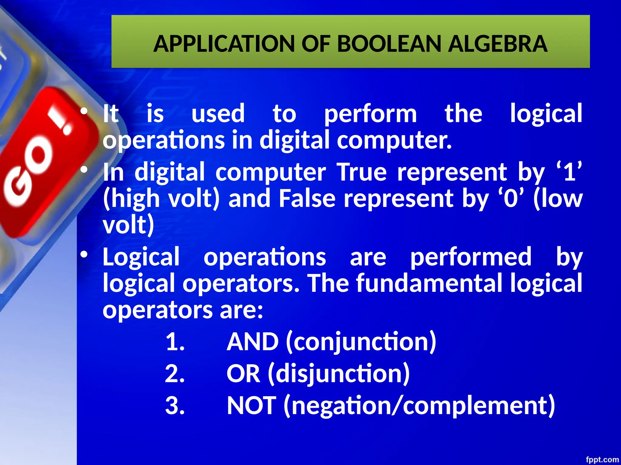
APPLICATION OF BOOLEANALGEBRA
• It is used to perform the logical
operations in digital computer.
• In digital computer True represent by ‘1’
(high volt) and False represent by ‘0’ (low
volt)
• Logical operations are performed by
logical operators. The fundamental logical
operators are:
1. AND (conjunction)
2. OR (disjunction)
3. NOT (negation/complement)
6.
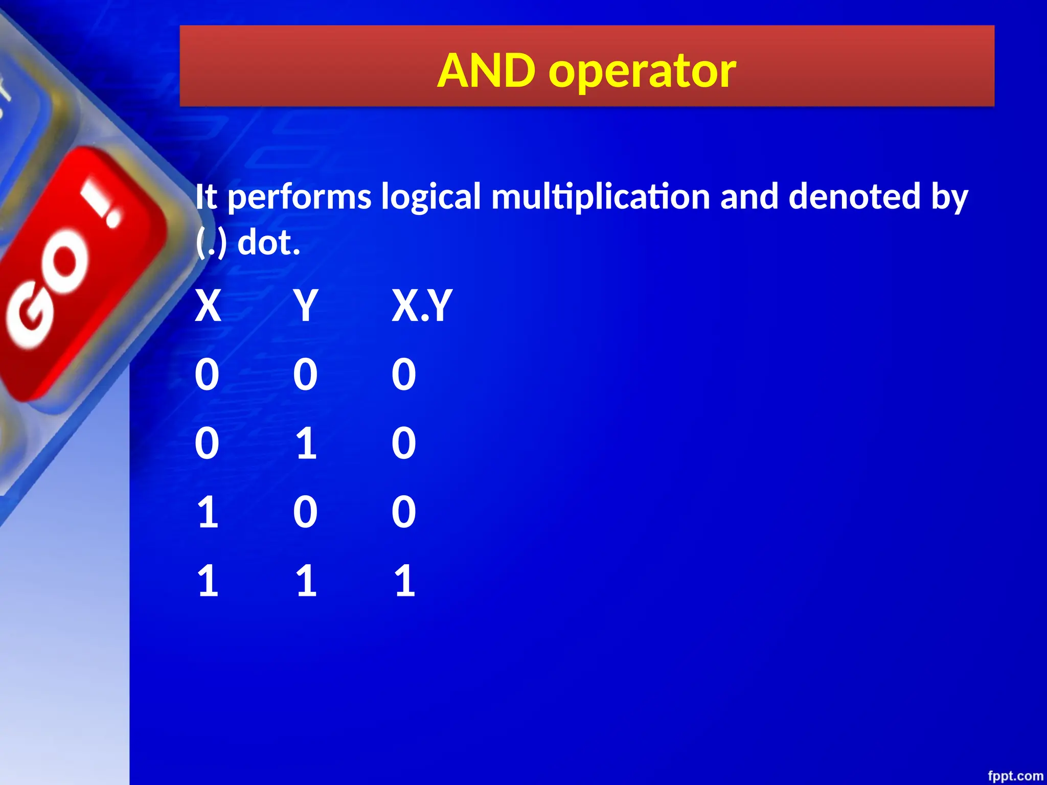
AND operator
It performslogical multiplication and denoted by
(.) dot.
X Y X.Y
0 0 0
0 1 0
1 0 0
1 1 1
7.
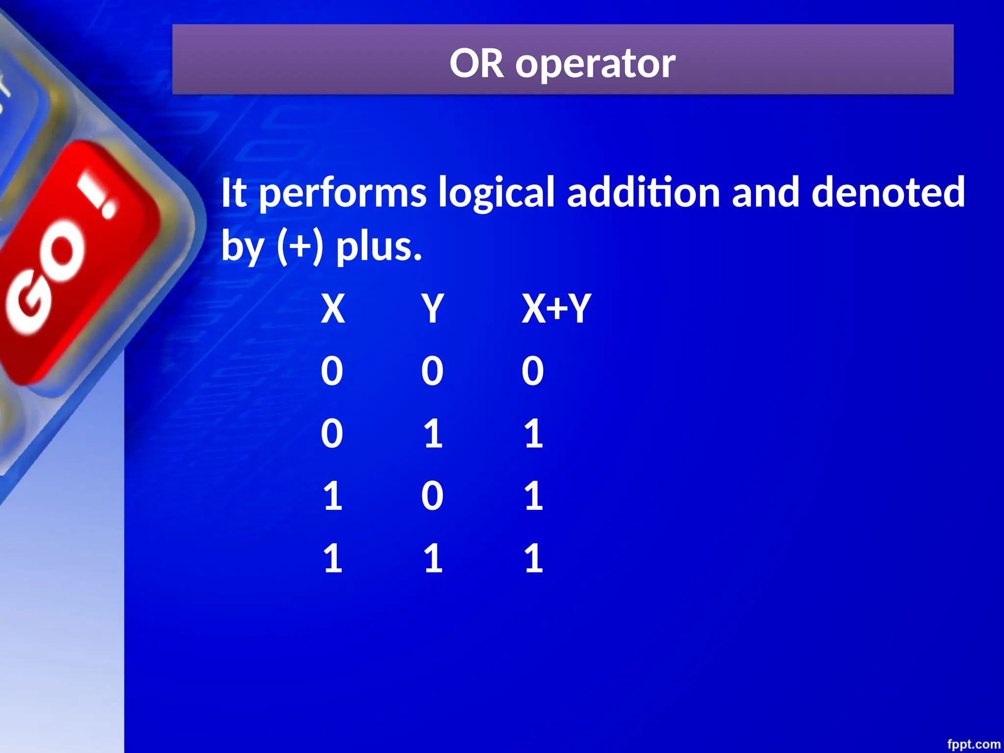
OR operator
It performslogical addition and denoted
by (+) plus.
X Y X+Y
0 0 0
0 1 1
1 0 1
1 1 1
8.
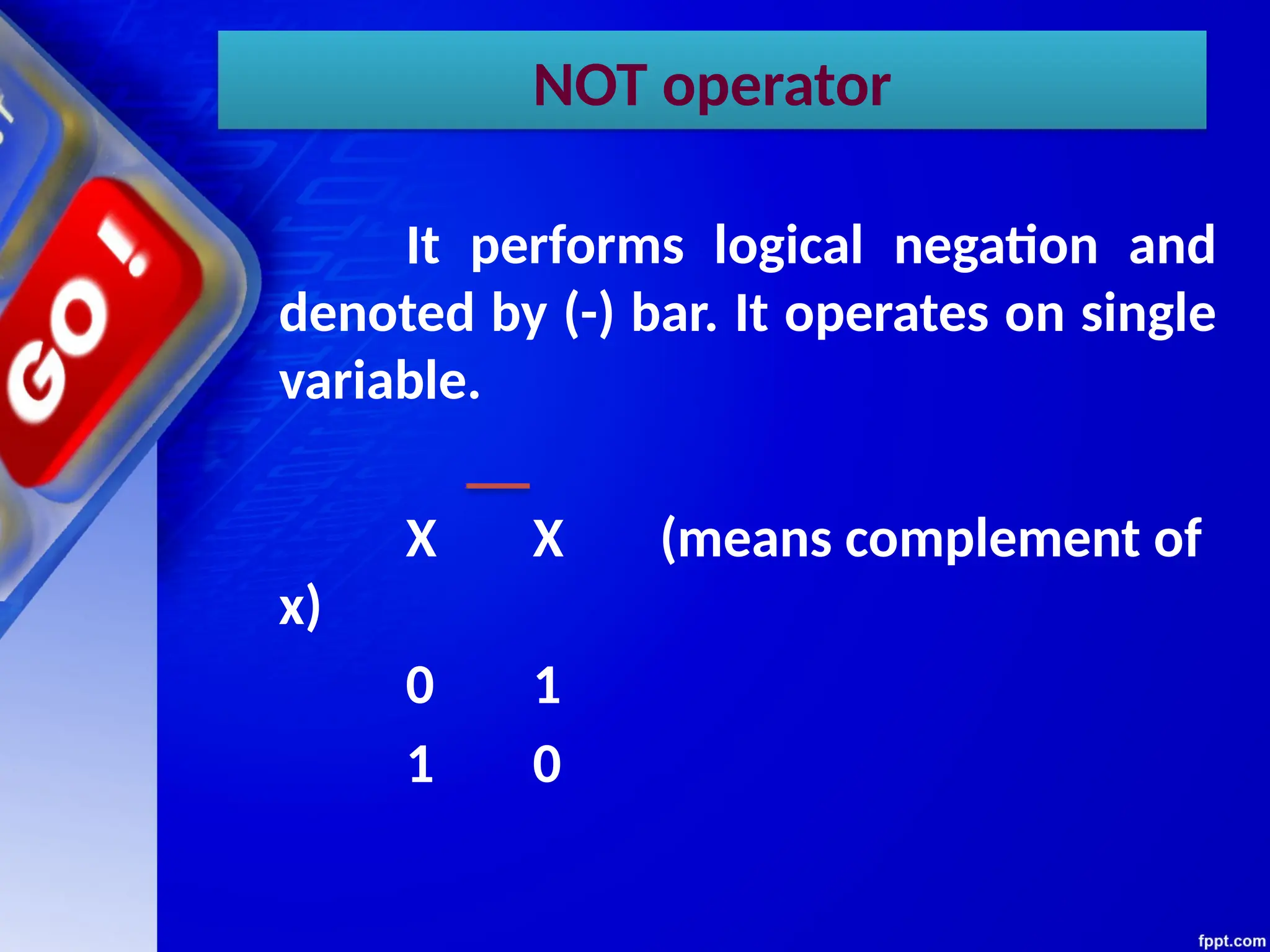
NOT operator
It performslogical negation and
denoted by (-) bar. It operates on single
variable.
X X (means complement of
x)
0 1
1 0
9.
Truth Table
• Truthtable is a table that contains all
possible values of logical
variables/statements in a Boolean
expression.
No. of possible combination =
2n
, where n=number of variables used in
a Boolean expression.
10.
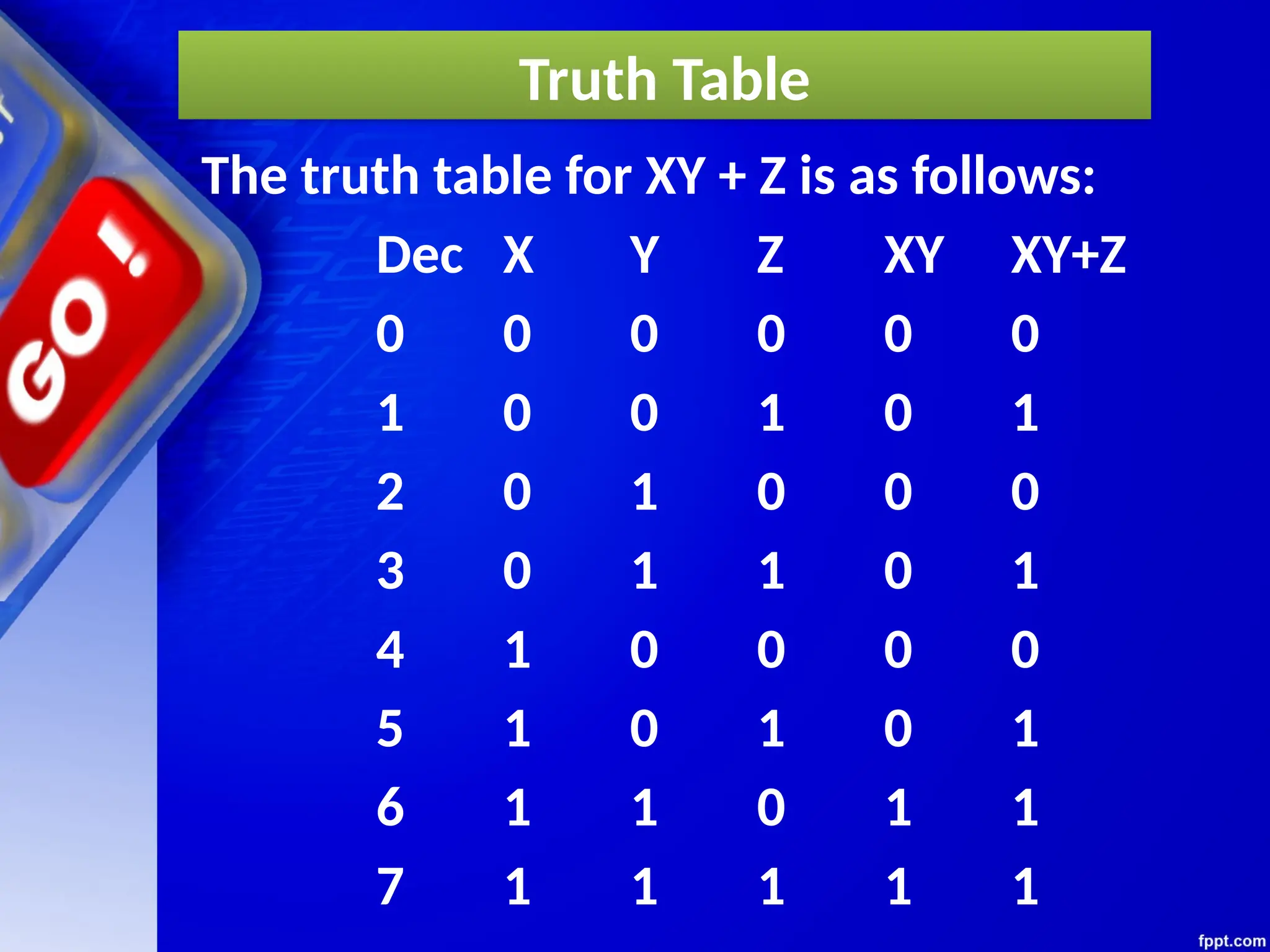
Truth Table
The truthtable for XY + Z is as follows:
Dec X Y Z XY XY+Z
0 0 0 0 0 0
1 0 0 1 0 1
2 0 1 0 0 0
3 0 1 1 0 1
4 1 0 0 0 0
5 1 0 1 0 1
6 1 1 0 1 1
7 1 1 1 1 1
11.
Tautology & Fallacy
Ifthe output of Boolean
expression is always True or 1 is
called Tautology.
If the output of Boolean
expression is always False or 0 is
called Fallacy.
Exercise
1. Evaluate thefollowing Boolean
expression using Truth Table.
(a) X’Y’+X’Y (b) X’YZ’+XY’
(c) XY’(Z+YZ’)+Z’
2. Verify that P+(PQ)’ is a Tautology.
3. Verify that (X+Y)’=X’Y’
14.
Implementation
Boolean Algebra appliedin
computers electronic circuits. These
circuits perform Boolean operations
and these are called logic circuits or
logic gates.
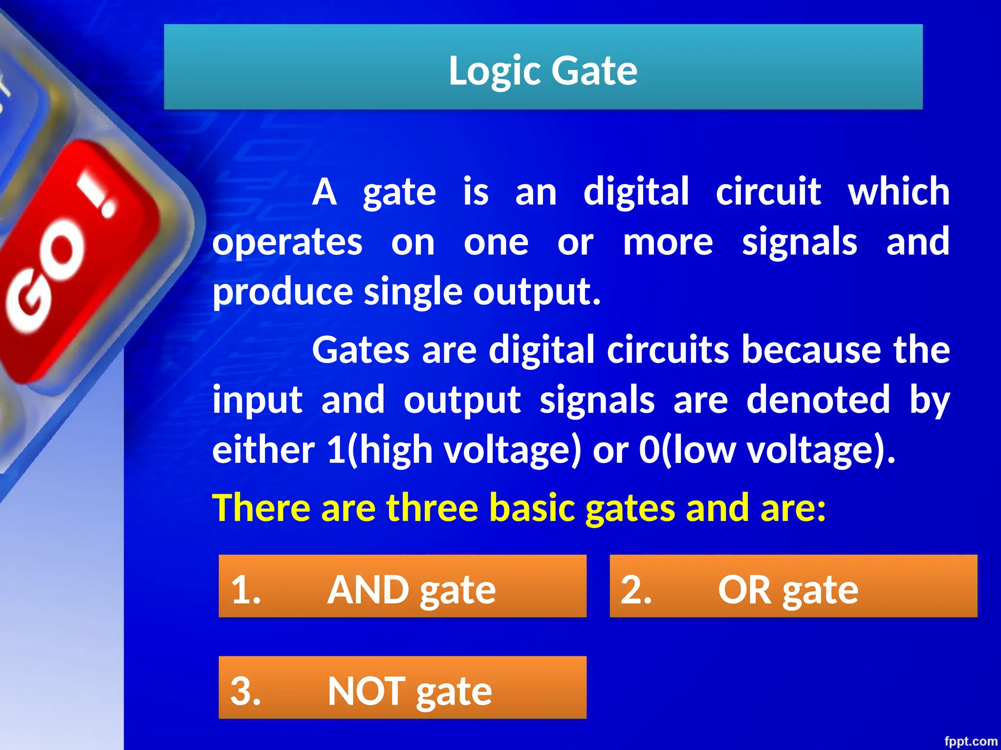
Logic Gate
A gateis an digital circuit which
operates on one or more signals and
produce single output.
Gates are digital circuits because the
input and output signals are denoted by
either 1(high voltage) or 0(low voltage).
There are three basic gates and are:
1. AND gate 2. OR gate
3. NOT gate
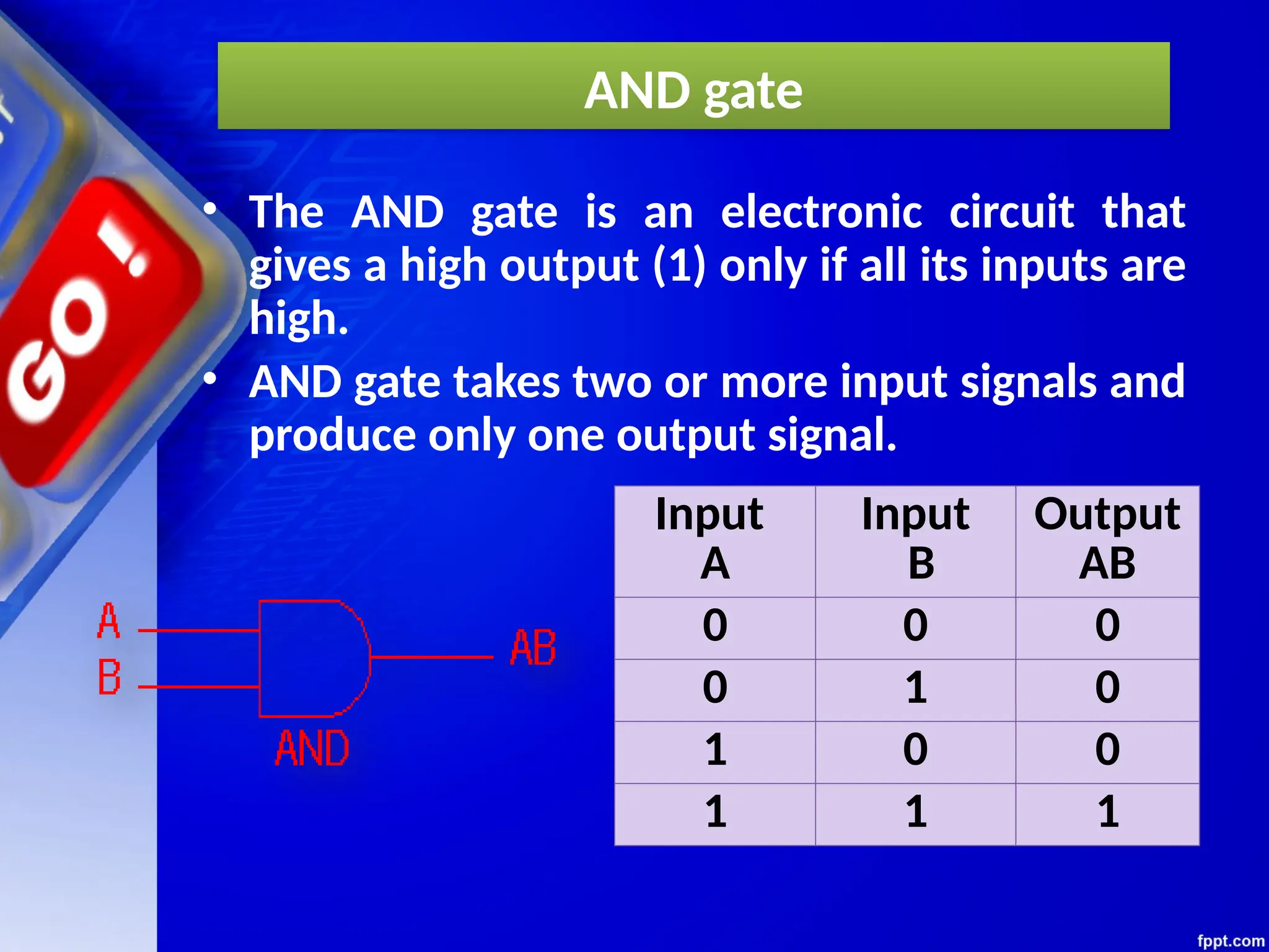
AND gate
• TheAND gate is an electronic circuit that
gives a high output (1) only if all its inputs are
high.
• AND gate takes two or more input signals and
produce only one output signal.
Input
A
Input
B
Output
AB
0 0 0
0 1 0
1 0 0
1 1 1
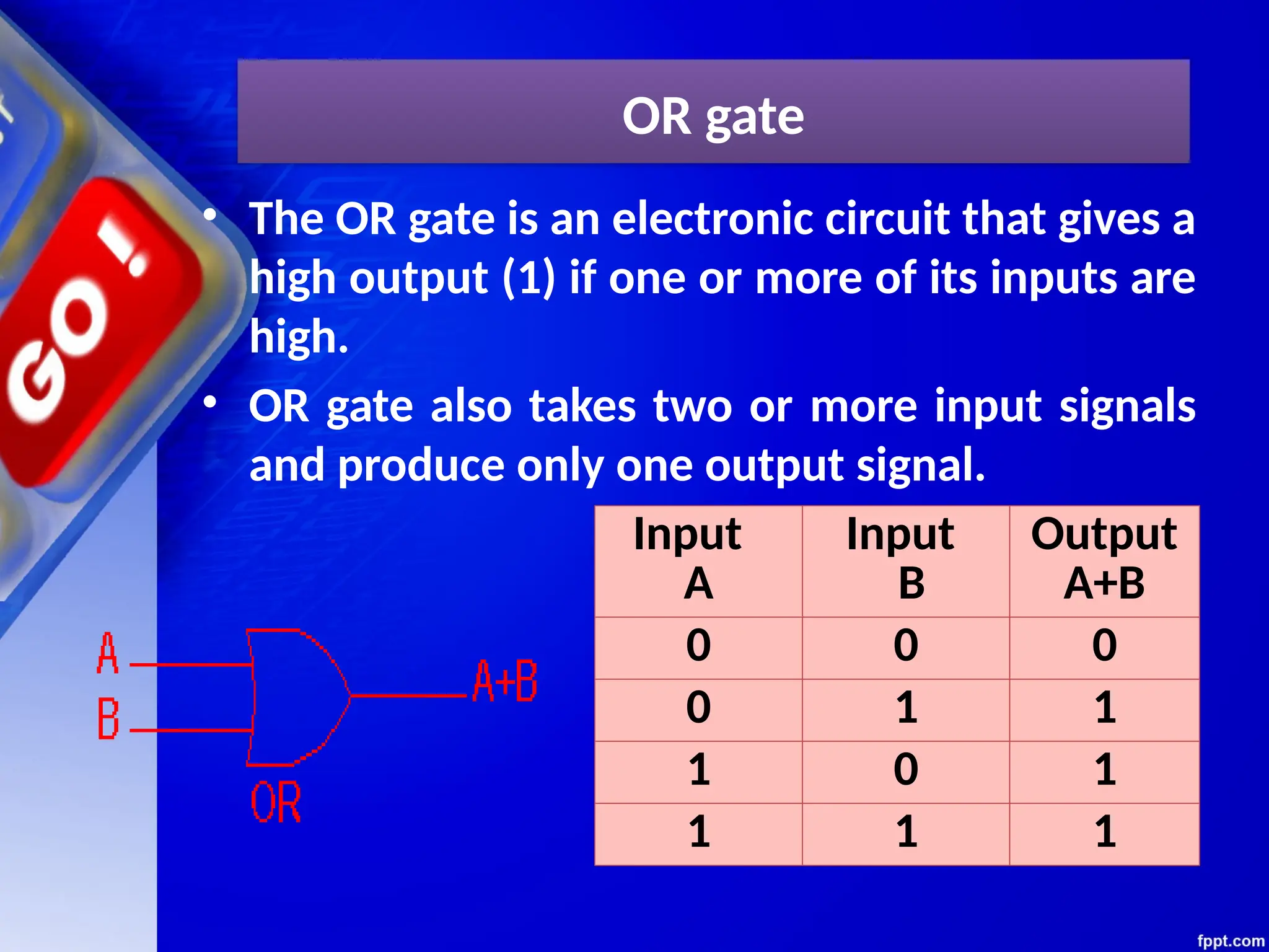
OR gate
• TheOR gate is an electronic circuit that gives a
high output (1) if one or more of its inputs are
high.
• OR gate also takes two or more input signals
and produce only one output signal.
Input
A
Input
B
Output
A+B
0 0 0
0 1 1
1 0 1
1 1 1
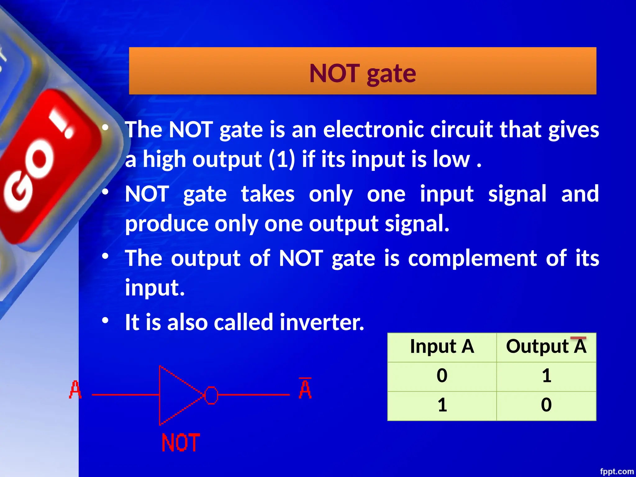
NOT gate
• TheNOT gate is an electronic circuit that gives
a high output (1) if its input is low .
• NOT gate takes only one input signal and
produce only one output signal.
• The output of NOT gate is complement of its
input.
• It is also called inverter.
Input A Output A
0 1
1 0
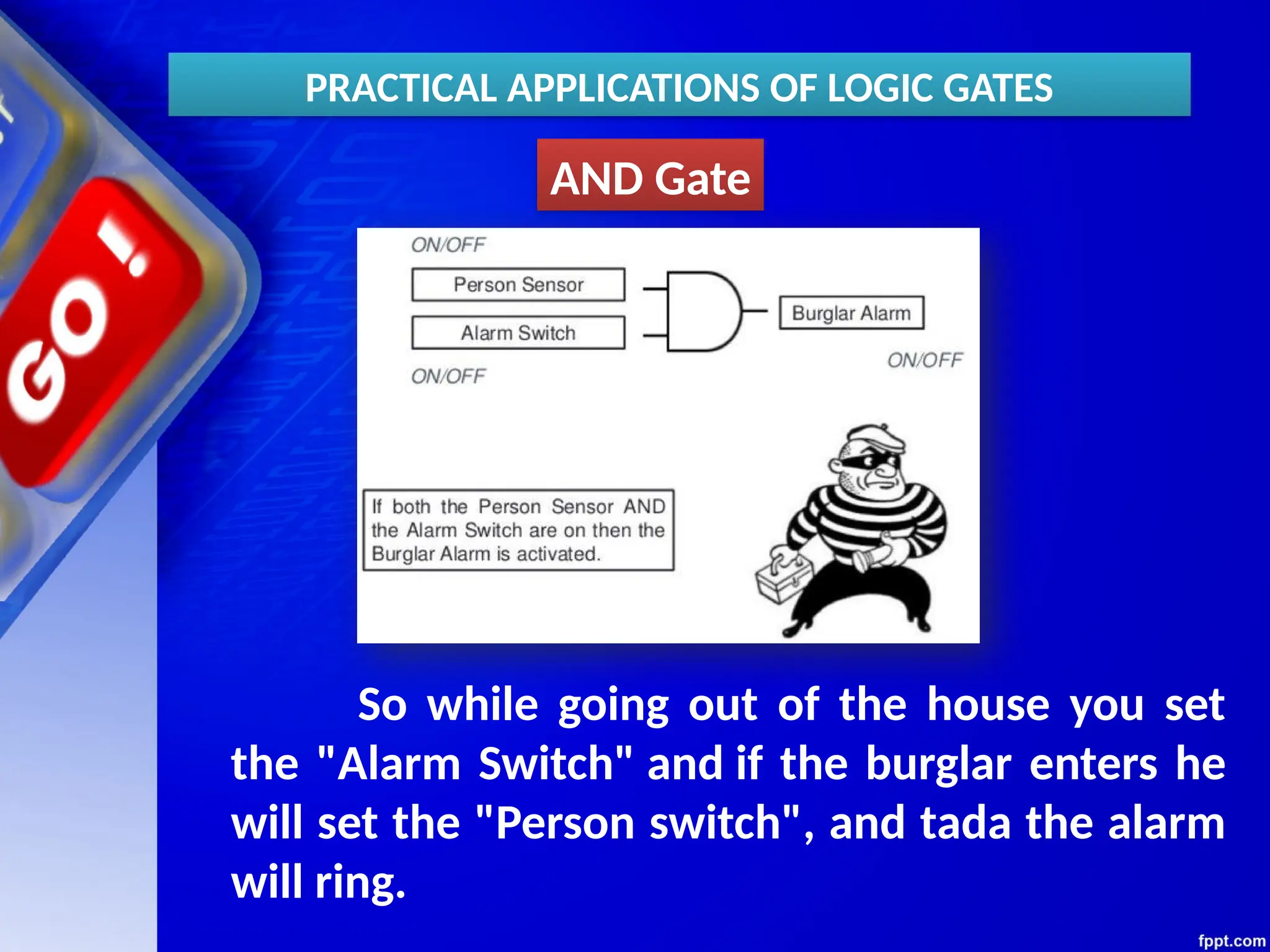
AND Gate
So whilegoing out of the house you set
the "Alarm Switch" and if the burglar enters he
will set the "Person switch", and tada the alarm
will ring.
PRACTICAL APPLICATIONS OF LOGIC GATES
25.
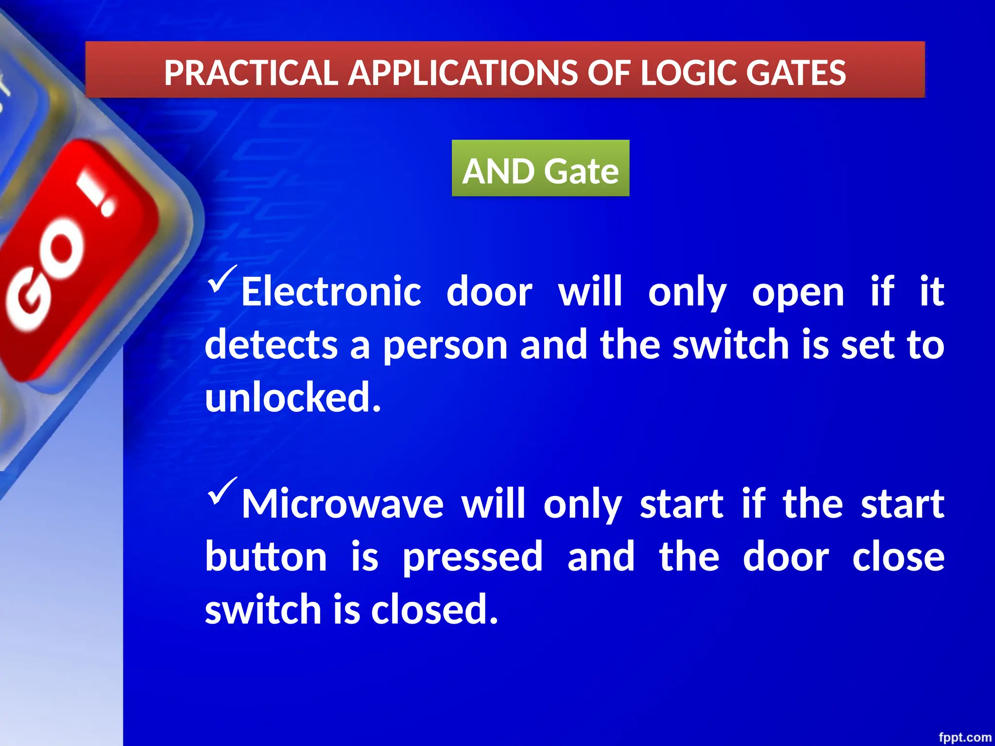
AND Gate
PRACTICAL APPLICATIONSOF LOGIC GATES
Electronic door will only open if it
detects a person and the switch is set to
unlocked.
Microwave will only start if the start
button is pressed and the door close
switch is closed.
26.
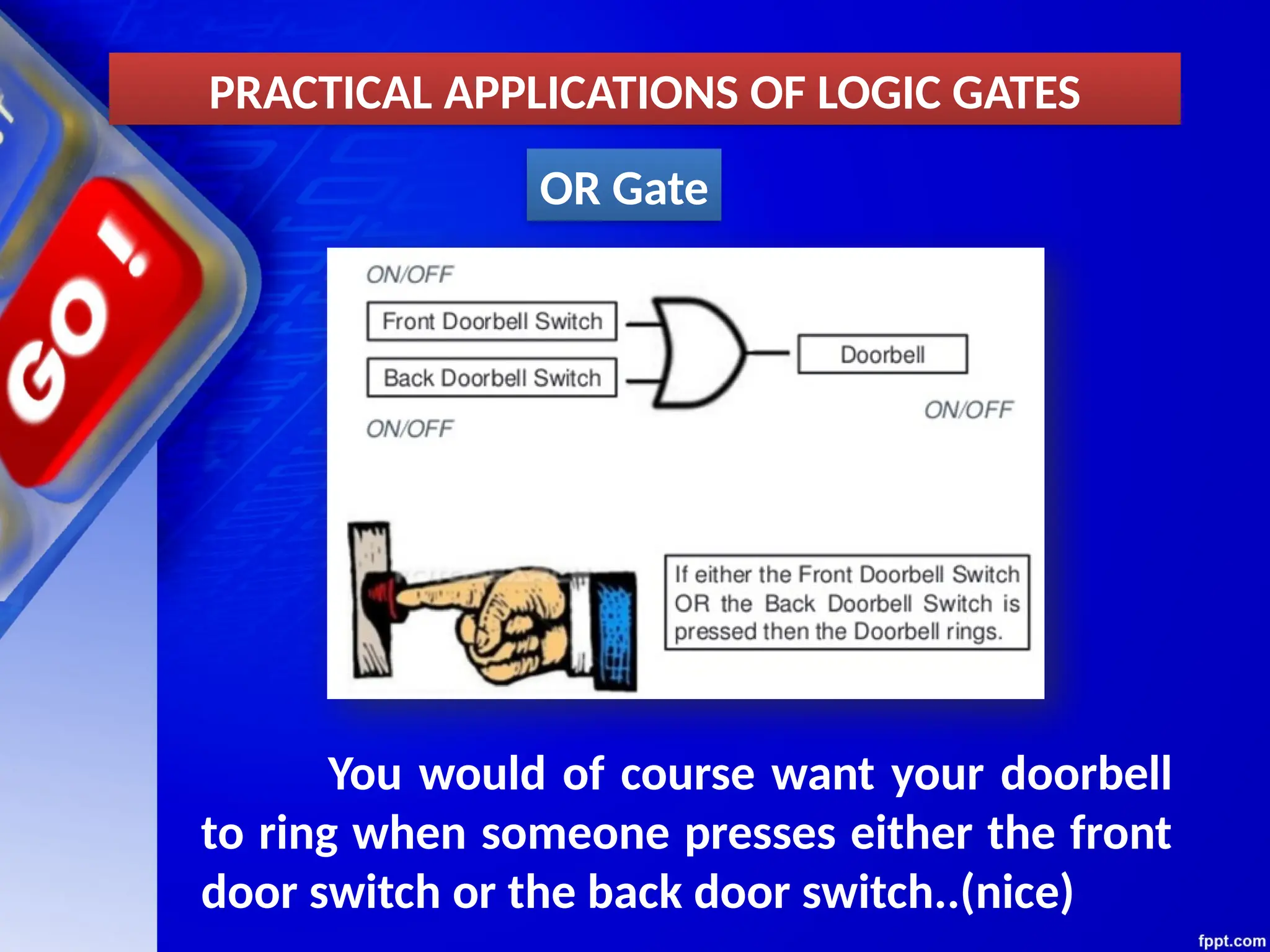
OR Gate
You wouldof course want your doorbell
to ring when someone presses either the front
door switch or the back door switch..(nice)
PRACTICAL APPLICATIONS OF LOGIC GATES
27.
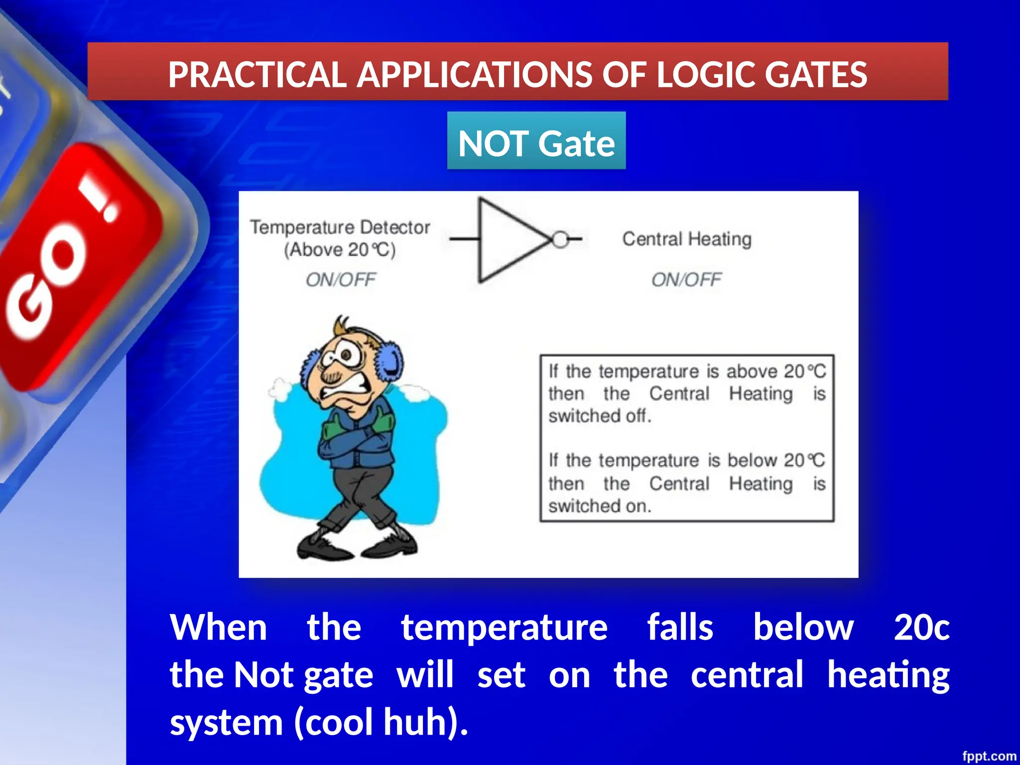
NOT Gate
When thetemperature falls below 20c
the Not gate will set on the central heating
system (cool huh).
PRACTICAL APPLICATIONS OF LOGIC GATES
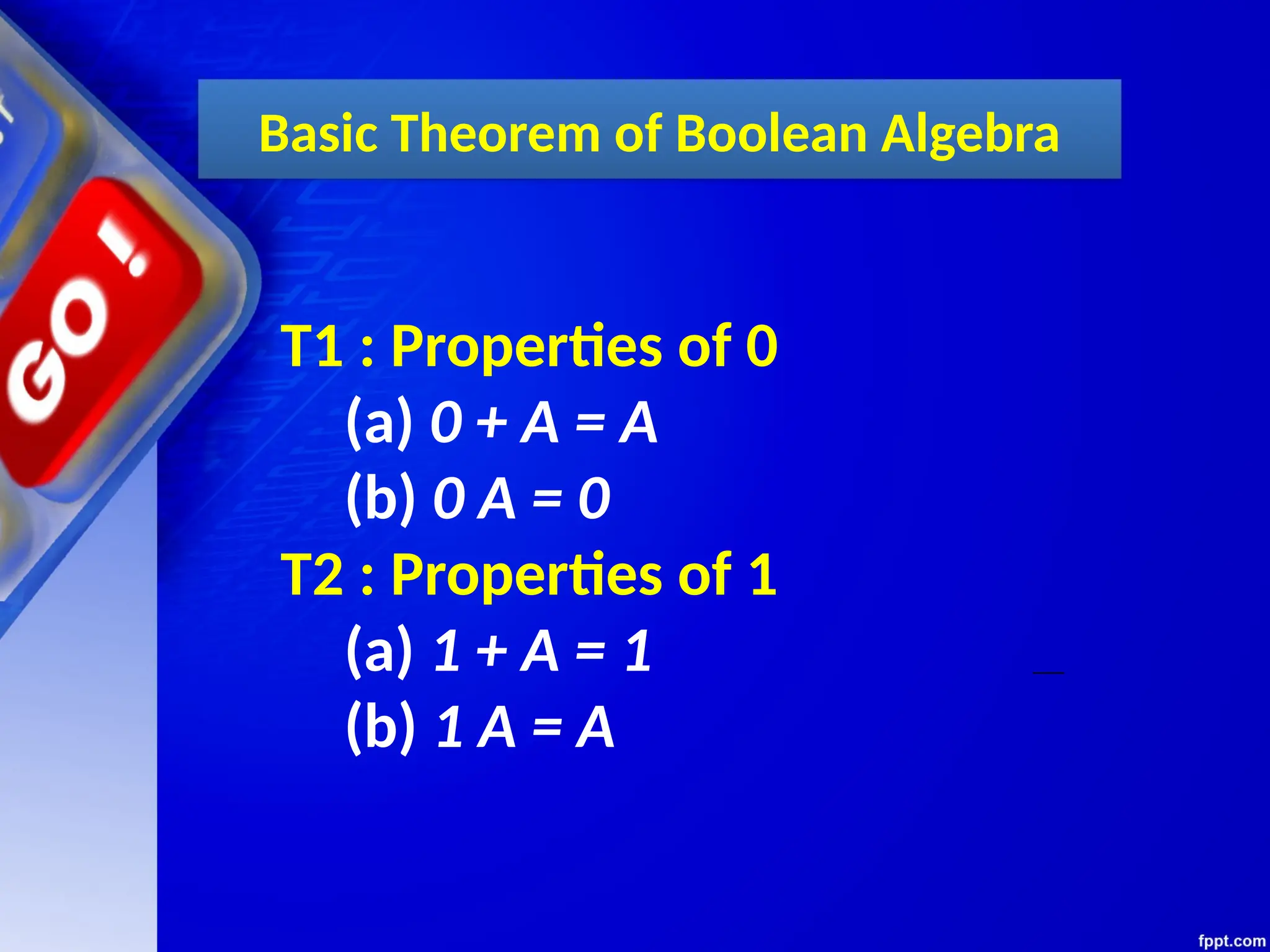
Basic Theorem ofBoolean Algebra
T1 : Properties of 0
(a) 0 + A = A
(b) 0 A = 0
T2 : Properties of 1
(a) 1 + A = 1
(b) 1 A = A
40.
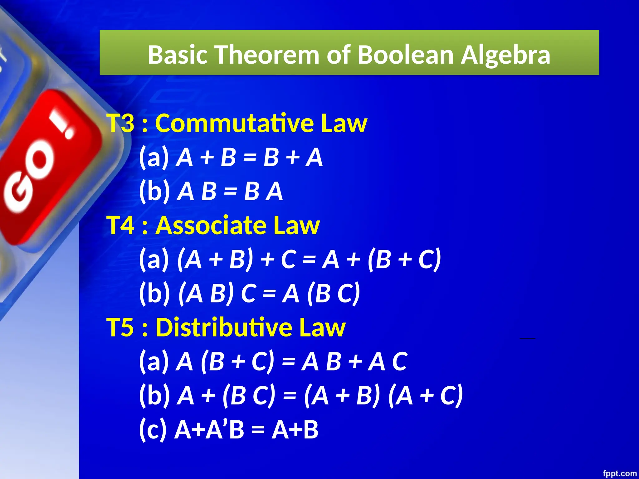
Basic Theorem ofBoolean Algebra
T3 : Commutative Law
(a) A + B = B + A
(b) A B = B A
T4 : Associate Law
(a) (A + B) + C = A + (B + C)
(b) (A B) C = A (B C)
T5 : Distributive Law
(a) A (B + C) = A B + A C
(b) A + (B C) = (A + B) (A + C)
(c) A+A’B = A+B
41.
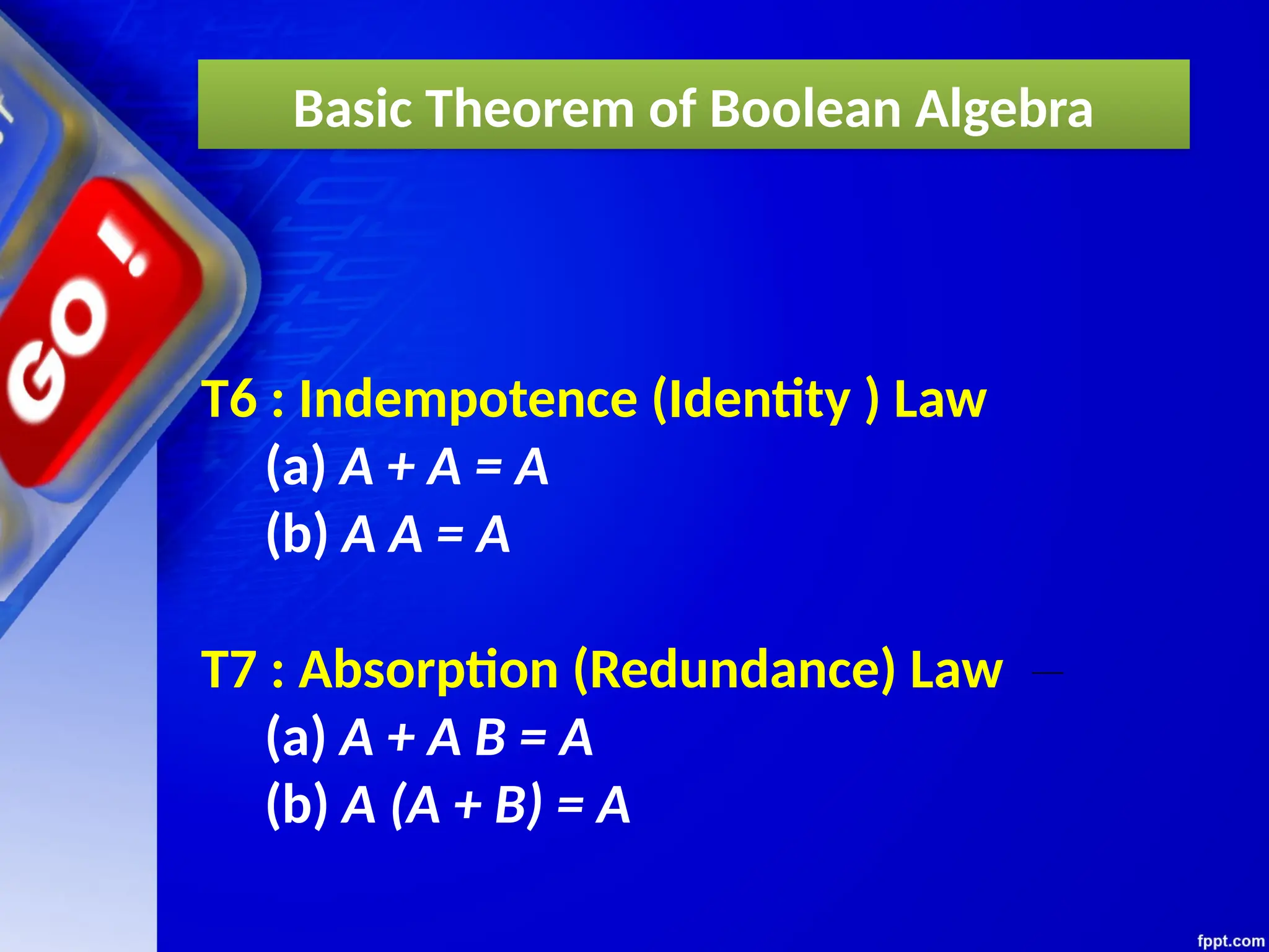
T6 : Indempotence(Identity ) Law
(a) A + A = A
(b) A A = A
T7 : Absorption (Redundance) Law
(a) A + A B = A
(b) A (A + B) = A
Basic Theorem of Boolean Algebra
42.
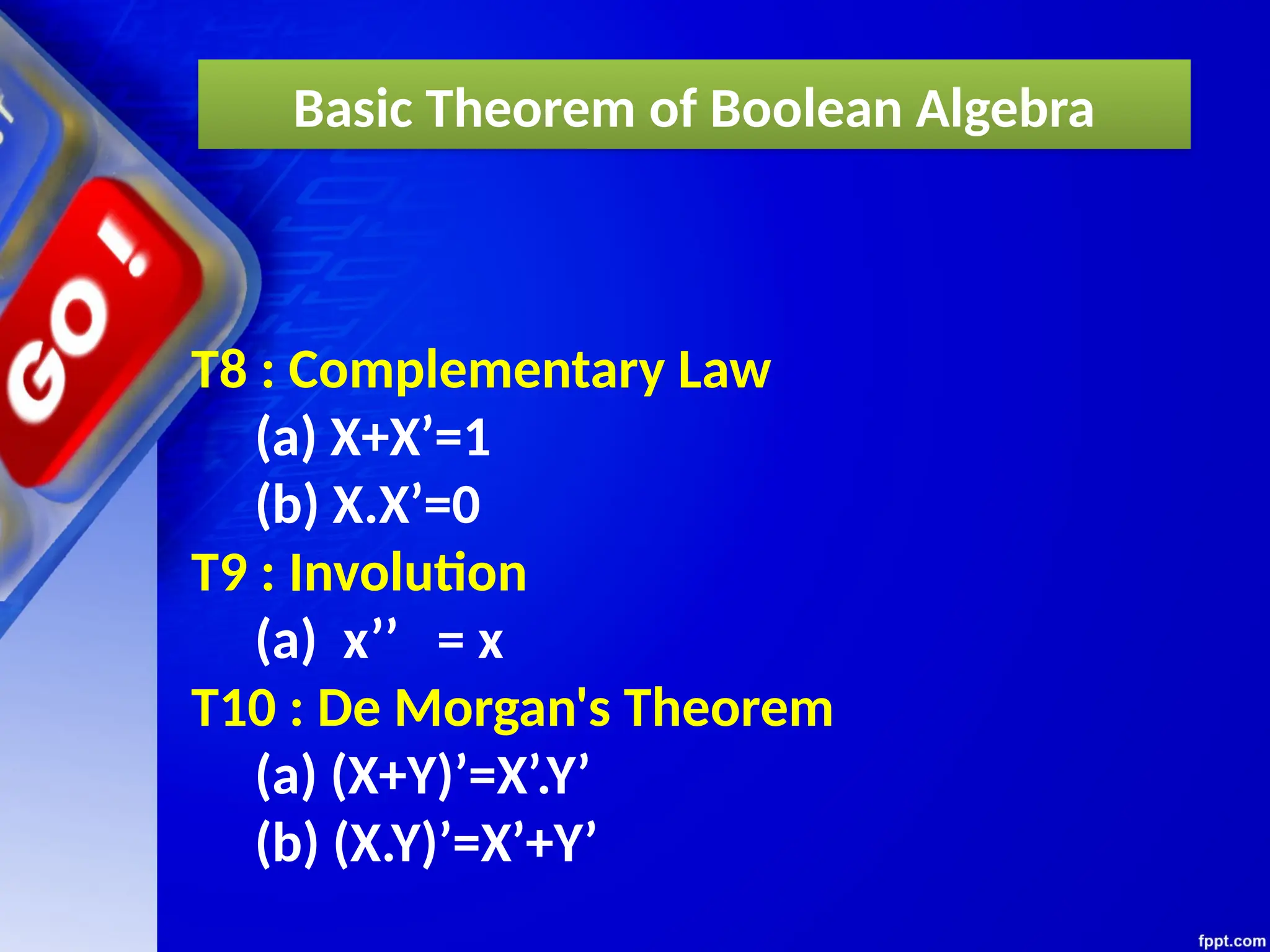
T8 : ComplementaryLaw
(a) X+X’=1
(b) X.X’=0
T9 : Involution
(a) x’’ = x
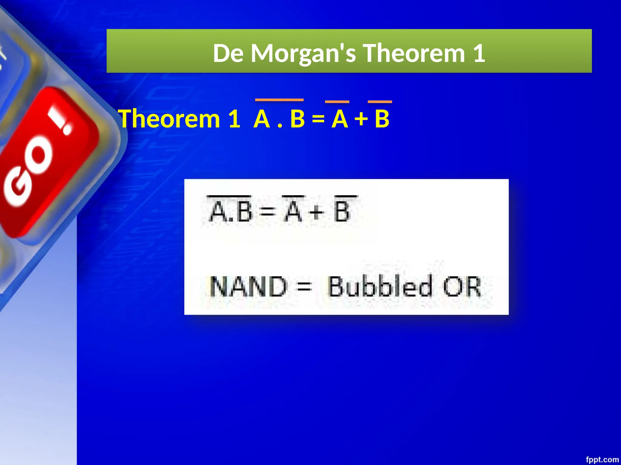
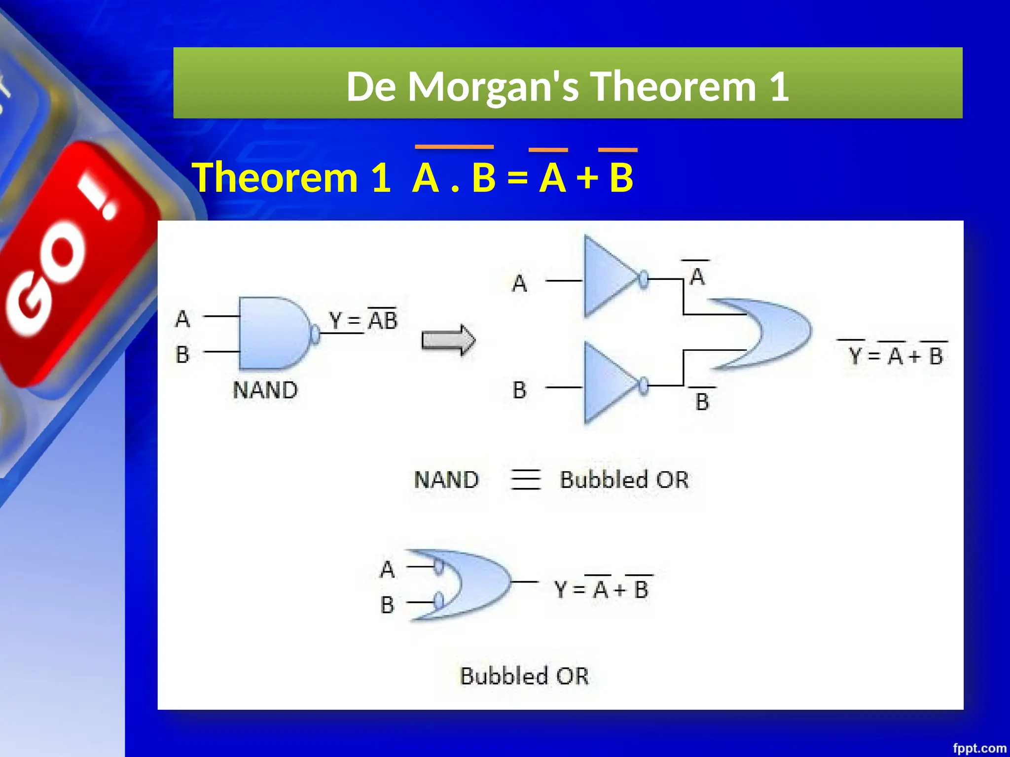
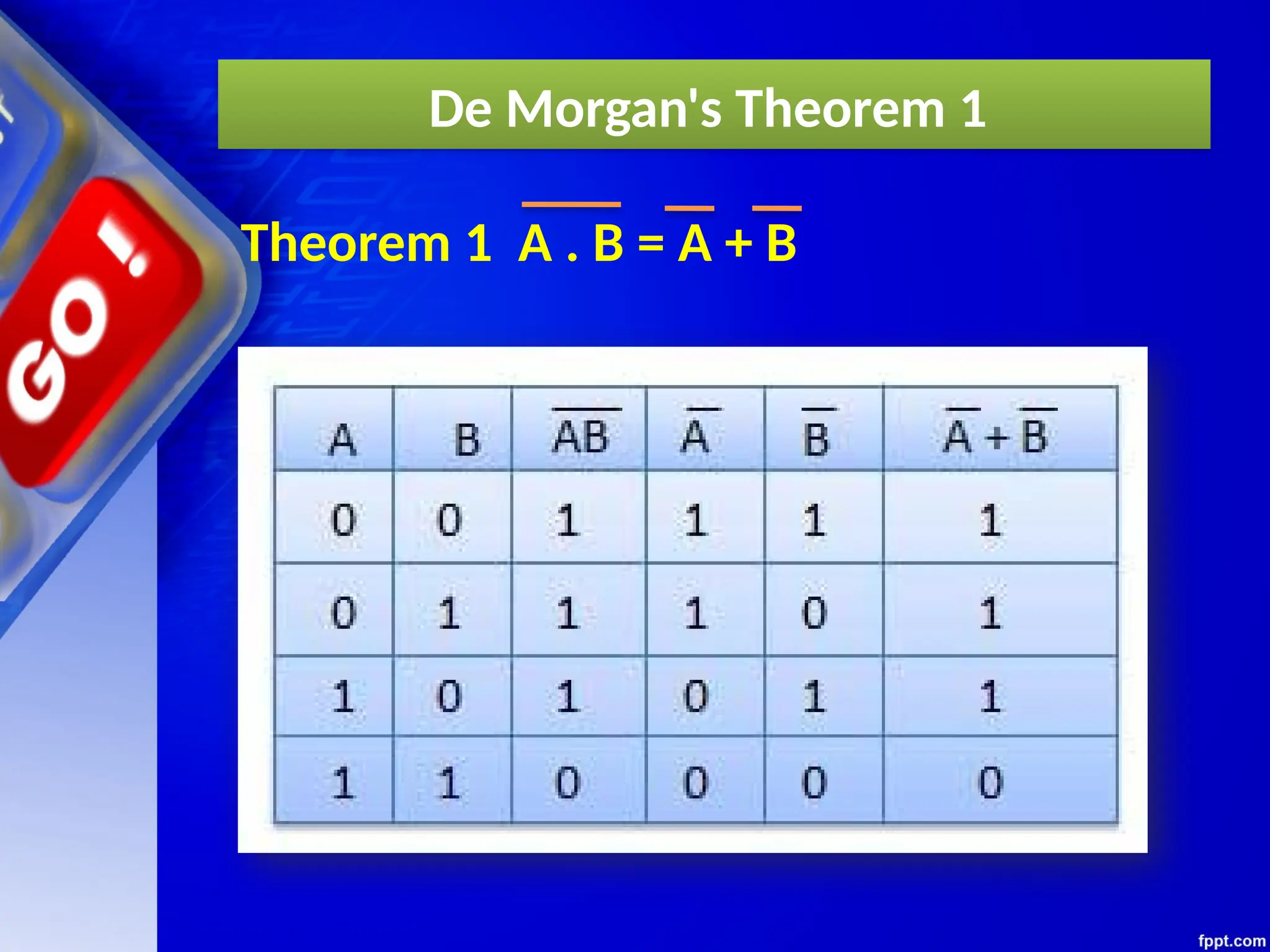
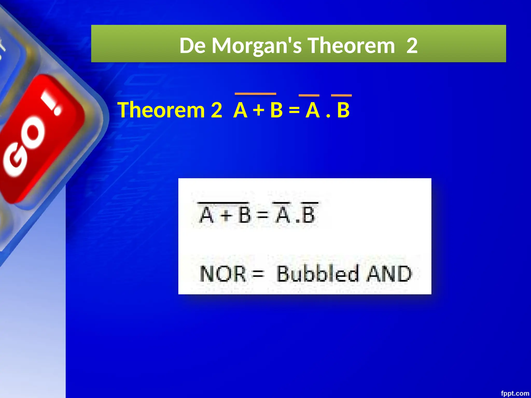
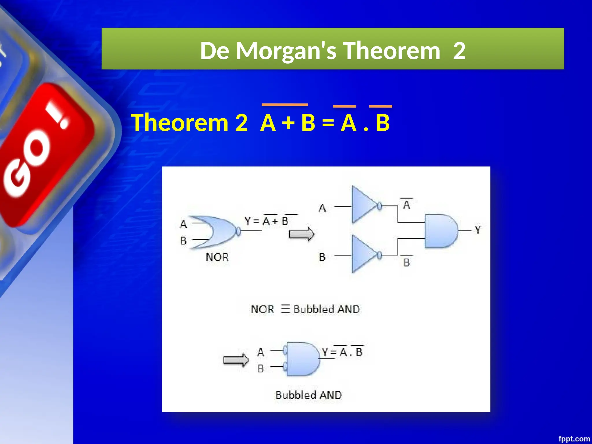
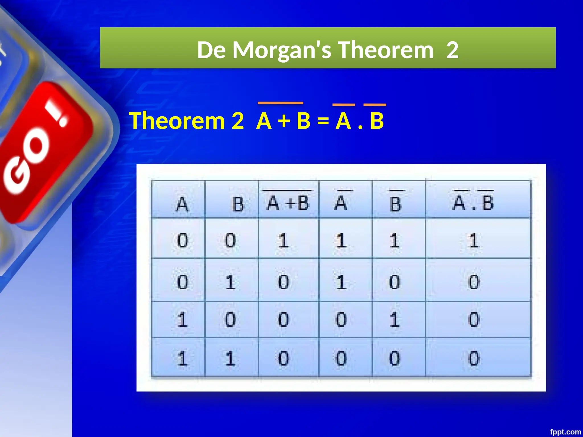
T10 : De Morgan's Theorem
(a) (X+Y)’=X’.Y’
(b) (X.Y)’=X’+Y’
Basic Theorem of Boolean Algebra


![Chapter 3 computer Boolean Algebra 2[1].pptx](https://cdn.slidesharecdn.com/ss_thumbnails/chapter3booleanalgebra21-240928031107-5861eb7e-thumbnail.jpg?width=640&height=640&fit=bounds)