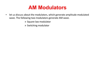
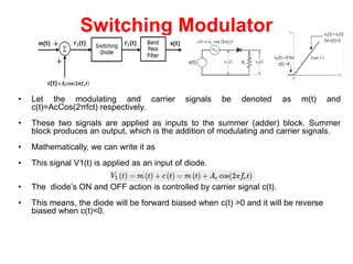
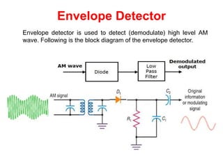
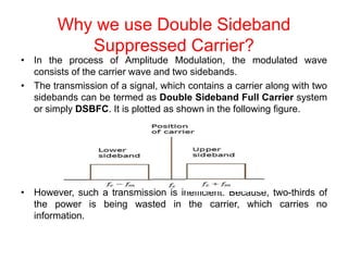
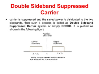
The document discusses amplitude modulation techniques. It describes the switching modulator, which uses a diode to generate an amplitude modulated wave by multiplying a carrier signal with the sum of the carrier and modulating signal. It then discusses the envelope detector, which uses a diode and low-pass filter to extract the modulating signal by detecting the envelope of the amplitude modulated wave. Finally, it explains double sideband suppressed carrier modulation, which suppresses the carrier wave to increase efficiency by distributing its power to the two sidebands.


![Envelope Detector (Contd.,)
• This envelope detector consists of a diode and low pass filter.
• Here, the diode is the main detecting element.
• Hence, the envelope detector is also called as the diode detector.
• The low pass filter contains a parallel combination of the resistor and the
capacitor.
• The AM wave s(t) is applied as an input to this detector.
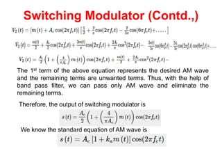
• We know the standard form of AM wave is
• s(t)=Ac[1+kam(t)]Cos(2πfct)
• In the positive half cycle of AM wave, the diode conducts and the capacitor
charges to the peak value of AM wave.
• When the value of AM wave is less than this value, the diode will be reverse
biased.
• Thus, the capacitor will discharge through resistor R till the next positive half
cycle of AM wave.
• When the value of AM wave is greater than the capacitor voltage, the diode
conducts and the process will be repeated.](https://image.slidesharecdn.com/unit-220920014919-717443d8/85/unit-pptx-7-320.jpg)
![Mathematical Expressions
Let us consider the same mathematical expressions for modulating and carrier
signals as we have considered in the earlier chapters.
Modulating signal
m(t)=AmCos(2πfm)t
Carrier signal
c(t)=AcCos(2πfc)t
Mathematically, we can represent the equation of DSBSC wave as the product of
modulating and carrier signals.
s(t)=m(t)c(t) ⇒s(t)=AmAcCos(2πfm)t * Cos(2πfc)t
Bandwidth of DSBSC Wave
We know the formula for bandwidth (BW) is
BW=fmax−fmin
Consider the equation of DSBSC modulated wave.
s(t)=AmAccos(2πfmt)cos(2πfct)
⇒s(t)=AmAc2cos[2π(fc+fm)t]+AmAc2cos[2π(fc−fm)t]
The DSBSC modulated wave has only two frequencies. So, the maximum and
minimum frequencies are fc+fm andfc−fm respectively. i.e., fmax=fc+fm
and fmin=fc−fm
Substitute, fmax and fminvalues in the bandwidth formula.
BW=(fc+fm)−(fc−fm) = 2fm](https://image.slidesharecdn.com/unit-220920014919-717443d8/85/unit-pptx-12-320.jpg)


