This document describes an MOPX separation system for purifying or clarifying oils. The key components are an MOPX separator, ancillary equipment including an EPC-41 control unit, and optional equipment. The system can operate automatically to separate sludge and water from oil. It provides benefits like flexibility to operate as a purifier or clarifier, simple installation and maintenance, and a preventive maintenance program.
1. Application
Purification or clarification of distillates, marine diesel oils,
intermediate and heavy fuel oils, and lubricating oils used in
marine installations and power stations.
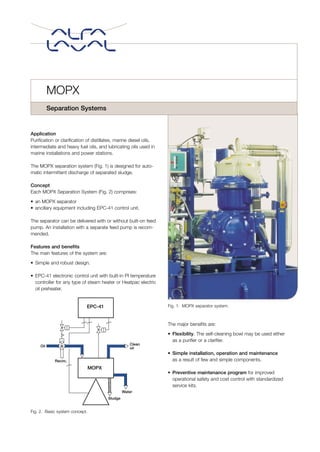
The MOPX separation system (Fig. 1) is designed for auto-
matic intermittent discharge of separated sludge.
Concept
Each MOPX Separation System (Fig. 2) comprises:
• an MOPX separator
• ancillary equipment including EPC-41 control unit.
The separator can be delivered with or without built-on feed
pump. An installation with a separate feed pump is recom-
mended.
Features and benefits
The main features of the system are:
• Simple and robust design.
• EPC-41 electronic control unit with built-in PI temperature
controller for any type of steam heater or Heatpac electric
oil preheater.
The major benefits are:
• Flexibility. The self-cleaning bowl may be used either
as a purifier or a clarifier.
• Simple installation, operation and maintenance
as a result of few and simple components.
• Preventive maintenance program for improved
operational safety and cost control with standardized
service kits.
MOPX
Separation Systems
Recirc.
Oil
EPC-41
MOPX
Clean
oil
Water
Sludge
Fig. 2. Basic system concept.
Fig. 1. MOPX separator system.
2. Fig. 3. Purifier–Clarifier.
1 Oil inlet
2 Oil outlet
3 Sludge outlet
4 Make-up and closing water inlet
5 Opening water inlet
6 Inlet for water seal and displacement
water
7 Water outlet
8 Water/oil interface
9a Gravity disc
9b Clarifier disc
10 Disc stack
11 Top disc
System working principle
The MOPX Separation System is
operated automatically by the EPC-41
control unit, except for starting the sep-
arator.
The MOPX separator bowl can be
arranged as a purifier or as a clarifier.
A purifier separates sludge and water
from the oil. Water is continuously dis-
charged from the bowl. The sludge
accumulated in the sludge space in
both a purifier and a clarifier is inter-
mittently discharged. In a clarifier, the
water outlet is blocked i.e. the water
handling capability is limited.
In the purifier mode, the EPC-41 unit
automatically controls the water admit-
ted to the separator for the water seal
and displacement of oil prior to sludge
discharge. During normal operation vital
process parameters are monitored. The
EPC-41 unit provides alarm functions
for broken water seal, low oil pressure,
high back pressure and power failure.
Alarm functions are also provided for
errors involving the EPC-41 unit.
In addition, functions are available for
high/low oil temperature alarm when
the optional Pt 100 temperature sensor
is fitted, and for vibration alarm when
the optional vibration switch is fitted.
When operating in the purifier mode, a
suitable gravity disc must be fitted to
obtain the correct interface position in
the separator bowl, i.e. the boundary
between the oil and the water seal. The
size of gravity disc must be selected to
match the oil density, viscosity/temper-
ature and oil feed rate to the separator.
In the clarifier mode, a clarifier disc is
fitted instead of gravity disc.
MOPX purifier MOPX clarifier
3. Installation
The MOPX Separation System is de-
signed for automatic operation in peri-
odically unmanned engine rooms at sea
and automated power stations ashore.
Each MOPX separator is equipped with
its own EPC-41 unit and ancillary equip-
ment, forming an independent system.
MOPX Separation Systems may be
operated in single, in parallel or in series.
For cleaning of distillate, marine diesel
oil, and lubricating oil, MOPX Separation
Systems should be operated in single
or parallel configuration, depending on
prevailing operational conditions. The
separators must then always be oper-
ated as purifiers.
If more than one MOPX Separation
System is installed in a plant for the
cleaning of intermediate or heavy fuel
oil, the systems should be operated in
series. In such a case, the first sepa-
rator should be operated as a purifier,
followed by the second separator oper-
ated as a clarifier.
Up to three separation systems in the
same cleaning plant can be intercon-
nected between their EPC-41 control
units; e.g. a purifier, a clarifier and a
standby separation system.
Basic system equipment (See Fig. 4)
1 MOPX separator with or without
built-on feed pump
2 Solenoid valve block, water
3 Emergency stop pushbutton
4 EPC-41 control unit
5 Solenoid valve block, air
6 Flexible hoses
7 High pressure switch
8 Low pressure switch
9 Pressure gauge
10 Regulating valve
11 Pneumatic 3-way valve
Selected spare parts for separator and
system equipment.
Additional equipment necessary
for operation
Electric motor and starter
Set of tools
Operating water tank
Separate oil feed pump with strainer
and starter (for separators without
built-on pump)
Oil heating system
Optional equipment
Vibration switch
Temperature sensor PT-100
MCFR flow regulation system
Air pressure reducing valve
Fig. 4. Schematic installation layout of an MOPX separation system.
4
2
6
11
10
9
8
7
1
3
5
Hot fresh
water
Fresh
water
Operating
water tank
Water
drain
Sludge
outlet
Separated water
outlet
Pre-
heater
Oil
feed
pump
Oil
recirculation
Oil
inlet
Clean oil
Compressed
air
Heater
power unit
Drain
Flexible
hoses
Starter
4. Modules
The separation system with supplemen-
tary equipment can be delivered as a
standardized plug-in unit, suitable for
both marine and power installations.
Technical documentation
Complete information and documen-
tation accompany each separation
system. Complete System Manual
covering separator and ancillary
equipment.
After Sales support
A Preventive Maintenance Program
has been developed, with two different
spare parts kits available corresponding
to two levels of service: every three
months, and every year of operation.
The kits can be ordered and stocked
as single units.
For further details of the Preventive
Maintenance Program contact your
nearest Alfa Laval representative. Our
service engineers are available to assist
you for any level of maintenance and to
train your maintenance engineers.
How to contact Alfa Laval
Contact details for all countries
are continually updated on our website.
Please visit www.alfalaval.com to
access the information direct.
160-PD1en-0108
Model
MOPX 205
MOPX 207
MOPX 309
MOPX 310
0 10000 20000
l/h
Throughput Capacities
Blue bars indicate range from
maximum recommended capacity on
600 cSt/50°C heavy fuel oil to max
recommended capacity on distillate
(1.5 to 6 cSt/40°C). For detailed
information on throughput capacities
see separate capacity table for indi-
vidual model.
MOPX 205 Weight: net 400 kg gross 530 kg Volume 1.55 m3
MOPX 207 ” ” 785 kg ” 950 kg ” 2.25 m3
MOPX 309/310 ” ” 1060 kg ” 1330 kg ” 3.88 m3
Shipping data