SlideShare a Scribd company logo
1 of 39
DESIGNANDANALYSISOFMULTI-STOREDRESIDENTIALBUILDING
INSTAADPRO
2018-2020
Under the esteemed guidance of
Mr. M V CH RAJESH
Assistant Professor
JITS DEPARTMENT OF CIVIL ENGINEERING
MASTER OF TECHNOLOGY
In
STRUCTURAL ENGINEERING
By
VEERAVALLI B N V S DURGA JYOTHI (18HE1D8717)
ABSTRACT
The principle objective of this project is to analyze and design a multi-storeyed
building [G + 21 (3 dimensional frame)] using STAAD Pro. The design involves load
calculations manually and analyzing the whole structure by STAAD Pro. The design
methods used in STAAD-Pro analysis are Limit State Design conforming to Indian
Standard Code of Practice. STAAD.Pro features a state-of-the-art user interface,
visualization tools, powerful analysis and design engines with advanced finite element and
dynamic analysis capabilities. From model generation, analysis and design to visualization
and result verification, STAAD.Pro is the professional’s choice. Initially we started with the
analysis of simple 2 dimensional frames and manually checked the accuracy of the software
with our results. The results proved to be very accurate.
INTRODUCTION
Our project involves analysis and design of multi-storeyed [G + 21] using
a very popular designing software STAAD Pro. We have chosen STAAD Pro
because of its following advantages:
• easy to use interface,
• conformation with the Indian Standard Codes,
• versatile nature of solving any type of problem,
• Accuracy of the solution.
LOADS CONSIDERED :
1. DEAD LOADS
2. IMPOSED LOADS
3. WIND LOADS
Design Wind Speed (V): The basic wind speed (V,) for any site shall be obtained from and shall be modified to
include the following effects to get design wind velocity at any height (V,) for the chosen structure:
a) Risk level
b) Terrain roughness, height and size of structure; and
c) Local topography.
It can be mathematically expressed as V = Vb * kl * k* ks
Vb = design wind speed at any height z in m/s
kl = probability factor (risk coefficient)
k = terrain, height and structure size factor
ks = topography factor
Risk Coefficient (kI Factor): gives basic wind speeds for terrain Category 2 as applicable at 10 m
above ground level based on 50 years mean return period. In the design of all buildings and structures,
a regional basic wind speed having a mean return period of 50 years shall be used.
Terrain, Height and Structure Size Factor (k, Factor): Terrain - Selection of terrain categories shall
be made with due regard to the effect of obstructions which constitute the ground surface roughness.
The terrain category used in the design of a structure may vary depending on the direction of wind
under consideration. Wherever sufficient meteorological information is available about the nature of
wind direction, the orientation of any building or structure may be suitably planned.
Topography (ks Factor) - The basic wind speed Vb takes account of the general level of site above sea
level. This does not allow for local topographic features such as hills, valleys, cliffs, escarpments, or
ridges which can significantly affect wind speed in their vicinity. The effect of topography is to
accelerate wind near the summits of hills or crests of cliffs, escarpments or ridges and decelerate the
wind in valleys or near the foot of cliff, steep escarpments, or ridges.
WIND PRESSURES AND FORCES ON BUILDINGS/STRUCTURES:
The wind load on a building shall be calculated for:
a) The building as a whole,
b) Individual structural elements as roofs and walls, and
c) Individual cladding units including glazing and their fixings.
Pressure Coefficients - The pressure coefficients are always given for a particular
surface or part of the surface of a building. The wind load acting normal to a surface is
obtained by multiplying the area of that surface or its appropriate portion by the pressure
coefficient (C,) and the design wind pressure at the height of the surface from the
ground.
F= (Cpe – Cpi).A.Pd
Where,
Cpe = external pressure coefficient,
Cpi = internal pressure- coefficient,
A = surface area of structural or cladding unit, and
Pd = design wind pressure element
SEISMIC LOAD
 Design Lateral Force
 Design Seismic Base Shear
 Fundamental Natural Period
 Distribution of Design Force
 Dynamic Analysis
 Time History Method
 Response Spectrum Method
WORKING WITH STAAD.Pro:
Input Generation:
The GUI (or user) communicates with the STAAD analysis engine through the STD input
file. That input file is a text file consisting of a series of commands which are executed
sequentially.
Types of Structures:
A STRUCTURE can be defined as an assemblage of elements. STAAD is capable of
analyzing and designing structures consisting of frame, plate/shell and solid elements.
Almost any type of structure can be analyzed by STAAD.
A SPACE structure, which is a three dimensional framed structure with loads applied in any
plane, is the most general.
A PLANE structure is bound by a global X-Y coordinate system with loads in the same
plane.
A TRUSS structure consists of truss members which can have only axial member forces and
no bending in the members.
A FLOOR structure is a two or three dimensional structure having no horizontal (global X
or Z) movement of the structure [FX, FZ & MY are restrained at every joint].
Generation of the structure
The structure may be generated from the input file or mentioning the co-ordinates
in the GUI. The figure below shows the GUI generation method.
Material Constants: The material constants are: modulus of elasticity (E); weight
density (DEN); Poisson's ratio (POISS); co-efficient of thermal expansion (ALPHA),
Composite Damping Ratio, and beta angle (BETA) or coordinates for any reference
(REF) point.
G = 0.5 x E/ (1 + POISS)
Supports: Supports are specified as PINNED, FIXED, or FIXED with different releases
(known as FIXED BUT). A pinned support has restraints against all translational
movement and none against rotational movement. In other words, a pinned support will
have reactions for all forces but will resist no moments.
LOADS: Loads in a structure can be specified as joint load, member load, temperature
load and fixed-end member load. STAAD can also generate the self-weight of the
structure and use it as uniformly distributed member loads in analysis. Any fraction of this
self weight can also be applied in any desired direction.
Member load:
Three types of member loads may be applied directly to a member of a structure. These loads
are uniformly distributed loads, concentrated loads, and linearly varying loads (including
trapezoidal).
Area/floor load: Many times a floor (bound by X-Z plane) is subjected to a uniformly
distributed load. It could require a lot of work to calculate the member load for individual
members in that floor. However, with the AREA or FLOOR LOAD command, the user can
specify the area loads (unit load per unit square area) for members.
Fixed end member load: Load effects on a member may also be specified in terms of its
fixed end loads. These loads are given in terms of the member coordinate system and the
directions are opposite to the actual load on the member.
Load Generator – Moving load, Wind & Seismic: Load generation is the process of taking
a load causing unit such as wind pressure, ground movement or a truck on a bridge, and
converting it to a form such as member load or a joint load which can be then be used in the
analysis.
Moving Load Generator: This feature enables the user to generate moving loads on
members of a structure. Moving load system(s) consisting of concentrated loads at fixed
specified distances in both directions on a plane can be defined by the user.
Seismic Load Generator: The STAAD seismic load generator follows the procedure of
equivalent lateral load analysis. It is assumed that the lateral loads will be exerted in X and Z
directions and Y will be the direction of the gravity loads.
Wind Load Generator: The STAAD Wind Load generator is capable of calculating wind
loads on joints of a structure from user specified wind intensities and exposure factors.
Different wind intensities may be specified for different height zones of the structure.
 Design Parameters
 Beam Design:
 Design for Flexure
 Design for Shear
 Column Design
 General Comments:
 Allowable Stresses
 Multiple Analyses
 Post Processing Facilities
 Stability Requirements
 Deflection Check
 Code Checking
ANALYSIS OF G + 21 RCC FRAMED BUILDING
USING STAAD.Pro
plan of the G+21 storey building
All columns = 0.50 * 0.50 m
(until ground floor)
Columns at the ground floor:
0.8 * 0.8 m
All beams = 0.3 * 0.5 m
All slabs = 0.20 m thick
Terracing = 0.2 m thick avg.
Parapet = 0.10 m thick RCC
elevation of the G+21 storey building
Physical parameters of building:
Length = 4 bays @ 5.0m = 20.0m Width = 3
bays @ 5 m =15.0m
Height = 4m + 21 storeys @ 3.3m = 73.3m
(1.0m parapet being non- structural for seismic purposes, is not considered of
building frame height)
Live load on the floors is 2kN/m2
Live load on the roof is 0.75kN/m2
Grade of concrete and steel used:
Used M30 concrete and Fe 415 steel
Generation of member property
Generation of member property can be done in STAAD.Pro by using the window as shown above. The
member section is selected and the dimensions have been specified. The beams are having a dimension of
0.5 * 0.3 m and the columns are having a dimension of 0.8 * 0.8 m at the ground floor and at the other top
floors they are having a dimension of 0.5 * 0.5 m.
Supports:
The base supports of the
structure were assigned as
fixed. The supports were
generated using the
STAAD.Pro support generator.
Materials for the structure:
The materials for the structure were specified as
concrete with their various constants as per
standard IS code of practice.
fixing supports of the structure
Loading:
primary load cases
input window of floor load generator load distribution by trapezoidal method
structure under DL from slab structure under live load
Wind load:
The wind load values were generated by the software itself in accordance with IS 875.
Under the define load command section, in the wind load category, the definition of wind
load was supplied. The wind intensities at various heights were calculated manually and
feed to the software. Based on those values it generates the wind load at different floors.
Height [h] Design wind Design wind
speed [Vz] pressure [Pz]
Up to 10 m 36.379 m/s 0.793 KN/sq m
15 m 38.85 m/s 0.905 KN/sq m
20 m 40.51 m/s 0.984 KN/sq m
30 m 42.58 m/s 1.087 KN/sq m
design wind pressure at various heights
wind load effect on structure elevation and plan
Floor Wi (KN) Hi(m) Hi2 Wi hi2 *103 (Wi hi2
Along x direction Along Y direction
level )/∑(Wi Qix Storey Qiy Storey
hi2)
shear shear
22 4129 73.3 5372.89 22184662.81 .123 426.309 372.15
21 4252 70 4900 20834800 .115 398.58 824 347.95 372.1
20 4252 66.7 4448.89 18916680.28 .105 363.9 1188 317.69 720.1
19 4252 63.4 4019.56 17091169.12 .0949 328.91 1517 272.3 1037
18 4252 60.1 3612.01 15358266.52 .085 294.60 1812 257.18 1310
17 4252 56.8 3226.24 13717972.48 .076 263.41 2075 229.95 1567
16 4252 53.5 2862.25 12170287 .067 232.2 2307 202.7 1797
15 4252 50.2 2520.04 10717972.18 .059 204.48 2512 178.5 1999
14 4252 46.9 2199.61 9352741.72 .0519 179.88 2692 157.03 2178
13 4252 43.6 1900.26 8082881.92 .044 152.50 2844 133.12 2335
12 4252 40.3 1624.09 6905630.68 .0383 132.74 2977 115.88 2468
11 4252 37 1369 5820988 .032 110.90 3110 96.82 2584
10 4252 33.7 1135.69 4828953.88 .0268 92.80 3221 81.08 2665
9 4252 30.4 924.16 3929528.32 .021 72.78 3314 63.53 2729
8 4252 27.1 734.41 3122711.32 .017 58.92 3386 51.43 2780
7 4252 23.8 566.41 2408502.88 .013 45.05 3445 39.33 2831
6 4252 20.5 420.25 1786903 .0099 34.31 3490 29.95 2871
5 4252 17.2 295.84 1257911.68 .0069 23.91 3525 20.87 2901
4 4252 13.9 193.21 821528.92 .0045 15.59 3549 13.61 2922
3 4252 10.6 112.36 477754.72 .0026 9.01 3564 7.866 2935
2 4252 7.3 53.29 226589.08 .00125 4.33 3573 3.782 2943
1 4505 4 16 72080 .0004 1.38 3577 1.210 2947
total 3579 2948
vertical distribution of earthquake forces to different floor levels
seismic load definition structure under seismic load
Load combination:
The structure has been analyzed for load combinations considering all the previous loads
in proper ratio. In the first case a combination of self-weight, dead load, live load and wind
load was taken in to consideration. In the second combination case instead of wind load
seismic load was taken into consideration.
under combination with wind load under combination with seismic load
GUI showing the analyzing window
DESIGN OF G + 21 RCC FRAMED BUILDING
USING STAAD.Pro
The structure was designed for concrete in accordance with IS code. The
parameters such as clear cover, Fy, Fc, etc were specified. The window shown below is the
input window for the design purpose. Then it has to be specified which members are to be
designed as beams and which member are to be designed as columns.
input window for design purpose. design specifications in STAAD.Pro
ANALYSIS AND DESIGN RESULTS
TOP 1714.02 0.00 273.43 1691.96 3487.90
REINF. (Sq. mm) (Sq. mm) (Sq. mm) (Sq. mm) (Sq. mm)
BOTTOM 3487.98 1692.06 293.58 273.43 1713.94
REINF. (Sq. mm) (Sq. mm) (Sq. mm) (Sq. mm) (Sq. mm)
Some of the sample analysis and design results have been shown below for beam number 149 which
is at the roof level of 1st floor.
7.1 B E A M N O. 149 D E S I G N R E S U L T S
M30 Fe415 (Main) Fe415 (Sec.)
LENGTH: 5000.0 mm SIZE: 500.0 mm X 300.0 mm COVER: 25.0 mm
SUMMARY OF REINFORCEMENT AREA (Sq.mm)
----------------------------------------------------------------------------------------------------------------
SECTION 0.0 mm 1250.0 mm 2500.0 mm 3750.0 mm 5000.0 mm
----------------------------------------------------------------------------------------------------------------
---------------------------------------------------------------------------------------------------------------
Geometry of beam no. 149 Property of beam no. 149
Shear bending of beam no. 149 Deflection of beam no. 149
Concrete design of beam no. 149
POST PROCESSING MODE
post processing mode in STAAD.Pro bending in Z
The stress at any point of any member can be found out in this mode. The figure below
depicts a particular case.
shear stress at any section
graph for shear force and bending moment for a column
CONCLUSION
STAAD PRO has the capability to calculate the reinforcement needed for any
concrete section. The program contains a number of parameters which are designed as per IS:
456(2000). Beams are designed for flexure, shear and torsion.
Design for Flexure: Maximum sagging (creating tensile stress at the bottom face of the
beam) and hogging (creating tensile stress at the top face) moments are calculated for all
active load cases at each of the above mentioned sections. Each of these sections are
designed to resist both of these critical sagging and hogging moments. Where ever the
rectangular section is inadequate as singly reinforced section, doubly reinforced section is
tried.
Design for Shear: Shear reinforcement is calculated to resist both shear forces and torsional
moments. Shear capacity calculation at different sections without the shear reinforcement is
based on the actual tensile reinforcement provided by STAAD program. Two-legged stirrups
are provided to take care of the balance shear forces acting on these sections.
Beam Design Output: The default design output of the beam contains flexural and shear
reinforcement provided along the length of the beam.
Column Design: Columns are designed for axial forces and biaxial moments at the ends. All
active load cases are tested to calculate reinforcement. The loading which yield maximum
reinforcement is called the critical load. Column design is done for square section. Square
columns are designed with reinforcement distributed on each side equally for the sections
under biaxial moments and with reinforcement distributed equally in two faces for sections
under uni-axial moment. All major criteria for selecting longitudinal and transverse
reinforcement as stipulated by IS: 456 have been taken care of in the column design of
STAAD.
Thank You

More Related Content

Similar to Project Staad pro.pptx

IRJET- Codal Comparison of IS-875 (Part 3) 1987 and IS-875 (Part 3) 2015 for ...
IRJET- Codal Comparison of IS-875 (Part 3) 1987 and IS-875 (Part 3) 2015 for ...IRJET- Codal Comparison of IS-875 (Part 3) 1987 and IS-875 (Part 3) 2015 for ...
IRJET- Codal Comparison of IS-875 (Part 3) 1987 and IS-875 (Part 3) 2015 for ...IRJET Journal
 
Analysis and Design of an Earthquake Resistant Structure using STADD. Pro
Analysis and Design of an Earthquake Resistant Structure using STADD. ProAnalysis and Design of an Earthquake Resistant Structure using STADD. Pro
Analysis and Design of an Earthquake Resistant Structure using STADD. ProIRJET Journal
 
Analysis and Design of G+19 Storied Building Using Staad-Pro
Analysis and Design of G+19 Storied Building Using Staad-ProAnalysis and Design of G+19 Storied Building Using Staad-Pro
Analysis and Design of G+19 Storied Building Using Staad-ProIJERA Editor
 
Group 2 , ce471
Group 2  ,  ce471Group 2  ,  ce471
Group 2 , ce471ktx500
 
1-Types of Structures and Loads.pdf
1-Types of Structures and Loads.pdf1-Types of Structures and Loads.pdf
1-Types of Structures and Loads.pdfYusfarijerjis
 
IRJET- Effect of Different Column Size on Joint Displacement of Building
IRJET- Effect of Different Column Size on Joint Displacement of BuildingIRJET- Effect of Different Column Size on Joint Displacement of Building
IRJET- Effect of Different Column Size on Joint Displacement of BuildingIRJET Journal
 
IRJET- Analysis of Diagrid Structure
IRJET-  	  Analysis of Diagrid StructureIRJET-  	  Analysis of Diagrid Structure
IRJET- Analysis of Diagrid StructureIRJET Journal
 
Performance Evaluation of G+5, G+10 and G+15 Story Symmetric and Asymmetric B...
Performance Evaluation of G+5, G+10 and G+15 Story Symmetric and Asymmetric B...Performance Evaluation of G+5, G+10 and G+15 Story Symmetric and Asymmetric B...
Performance Evaluation of G+5, G+10 and G+15 Story Symmetric and Asymmetric B...IRJET Journal
 
Comparative Analysis of an RC framed building under Seismic Conditions
Comparative Analysis of an RC framed building under Seismic ConditionsComparative Analysis of an RC framed building under Seismic Conditions
Comparative Analysis of an RC framed building under Seismic ConditionsIRJET Journal
 
Performance of High-Rise Steel Building With and Without Bracings
Performance of High-Rise Steel Building With and Without BracingsPerformance of High-Rise Steel Building With and Without Bracings
Performance of High-Rise Steel Building With and Without BracingsIJERA Editor
 
Analysis of 3+ story building in staad pro
Analysis of 3+ story building in staad proAnalysis of 3+ story building in staad pro
Analysis of 3+ story building in staad proCADmantra Technologies
 
IRJET-Comparative Study on Design Results of a Multi-Storied Building using S...
IRJET-Comparative Study on Design Results of a Multi-Storied Building using S...IRJET-Comparative Study on Design Results of a Multi-Storied Building using S...
IRJET-Comparative Study on Design Results of a Multi-Storied Building using S...IRJET Journal
 
SEISMIC ANALYSIS OF G+7 RESIDENTIAL BUILDING WITH AND WITHOUT SHEAR WALL
SEISMIC ANALYSIS OF G+7 RESIDENTIAL BUILDING WITH AND WITHOUT SHEAR WALLSEISMIC ANALYSIS OF G+7 RESIDENTIAL BUILDING WITH AND WITHOUT SHEAR WALL
SEISMIC ANALYSIS OF G+7 RESIDENTIAL BUILDING WITH AND WITHOUT SHEAR WALLIRJET Journal
 
Analysis, Design and Estimation of Basement +G+2 Residential Building
Analysis, Design and Estimation of Basement +G+2 Residential BuildingAnalysis, Design and Estimation of Basement +G+2 Residential Building
Analysis, Design and Estimation of Basement +G+2 Residential BuildingIRJET Journal
 
Comparative Study on Analysis of G+10 Regular Residential Building subjected ...
Comparative Study on Analysis of G+10 Regular Residential Building subjected ...Comparative Study on Analysis of G+10 Regular Residential Building subjected ...
Comparative Study on Analysis of G+10 Regular Residential Building subjected ...IRJET Journal
 
Seismic Design of RC Diaphragms, Chords, and Collectors
Seismic Design of RC Diaphragms, Chords, and CollectorsSeismic Design of RC Diaphragms, Chords, and Collectors
Seismic Design of RC Diaphragms, Chords, and CollectorsRuangRangka
 
IRJET- Comparative Analysis of Seismic Performance of R.C Building Restin...
IRJET-  	  Comparative Analysis of Seismic Performance of R.C Building Restin...IRJET-  	  Comparative Analysis of Seismic Performance of R.C Building Restin...
IRJET- Comparative Analysis of Seismic Performance of R.C Building Restin...IRJET Journal
 

Similar to Project Staad pro.pptx (20)

IRJET- Codal Comparison of IS-875 (Part 3) 1987 and IS-875 (Part 3) 2015 for ...
IRJET- Codal Comparison of IS-875 (Part 3) 1987 and IS-875 (Part 3) 2015 for ...IRJET- Codal Comparison of IS-875 (Part 3) 1987 and IS-875 (Part 3) 2015 for ...
IRJET- Codal Comparison of IS-875 (Part 3) 1987 and IS-875 (Part 3) 2015 for ...
 
Analysis and Design of an Earthquake Resistant Structure using STADD. Pro
Analysis and Design of an Earthquake Resistant Structure using STADD. ProAnalysis and Design of an Earthquake Resistant Structure using STADD. Pro
Analysis and Design of an Earthquake Resistant Structure using STADD. Pro
 
E0344042054
E0344042054E0344042054
E0344042054
 
Analysis and Design of G+19 Storied Building Using Staad-Pro
Analysis and Design of G+19 Storied Building Using Staad-ProAnalysis and Design of G+19 Storied Building Using Staad-Pro
Analysis and Design of G+19 Storied Building Using Staad-Pro
 
Group 2 , ce471
Group 2  ,  ce471Group 2  ,  ce471
Group 2 , ce471
 
1-Types of Structures and Loads.pdf
1-Types of Structures and Loads.pdf1-Types of Structures and Loads.pdf
1-Types of Structures and Loads.pdf
 
IRJET- Effect of Different Column Size on Joint Displacement of Building
IRJET- Effect of Different Column Size on Joint Displacement of BuildingIRJET- Effect of Different Column Size on Joint Displacement of Building
IRJET- Effect of Different Column Size on Joint Displacement of Building
 
IRJET- Analysis of Diagrid Structure
IRJET-  	  Analysis of Diagrid StructureIRJET-  	  Analysis of Diagrid Structure
IRJET- Analysis of Diagrid Structure
 
Performance Evaluation of G+5, G+10 and G+15 Story Symmetric and Asymmetric B...
Performance Evaluation of G+5, G+10 and G+15 Story Symmetric and Asymmetric B...Performance Evaluation of G+5, G+10 and G+15 Story Symmetric and Asymmetric B...
Performance Evaluation of G+5, G+10 and G+15 Story Symmetric and Asymmetric B...
 
D012211830
D012211830D012211830
D012211830
 
Comparative Analysis of an RC framed building under Seismic Conditions
Comparative Analysis of an RC framed building under Seismic ConditionsComparative Analysis of an RC framed building under Seismic Conditions
Comparative Analysis of an RC framed building under Seismic Conditions
 
Performance of High-Rise Steel Building With and Without Bracings
Performance of High-Rise Steel Building With and Without BracingsPerformance of High-Rise Steel Building With and Without Bracings
Performance of High-Rise Steel Building With and Without Bracings
 
Analysis of 3+ story building in staad pro
Analysis of 3+ story building in staad proAnalysis of 3+ story building in staad pro
Analysis of 3+ story building in staad pro
 
IRJET-Comparative Study on Design Results of a Multi-Storied Building using S...
IRJET-Comparative Study on Design Results of a Multi-Storied Building using S...IRJET-Comparative Study on Design Results of a Multi-Storied Building using S...
IRJET-Comparative Study on Design Results of a Multi-Storied Building using S...
 
SEISMIC ANALYSIS OF G+7 RESIDENTIAL BUILDING WITH AND WITHOUT SHEAR WALL
SEISMIC ANALYSIS OF G+7 RESIDENTIAL BUILDING WITH AND WITHOUT SHEAR WALLSEISMIC ANALYSIS OF G+7 RESIDENTIAL BUILDING WITH AND WITHOUT SHEAR WALL
SEISMIC ANALYSIS OF G+7 RESIDENTIAL BUILDING WITH AND WITHOUT SHEAR WALL
 
Analysis, Design and Estimation of Basement +G+2 Residential Building
Analysis, Design and Estimation of Basement +G+2 Residential BuildingAnalysis, Design and Estimation of Basement +G+2 Residential Building
Analysis, Design and Estimation of Basement +G+2 Residential Building
 
Session 2 - Using STAAD (1).pdf
Session 2 - Using STAAD (1).pdfSession 2 - Using STAAD (1).pdf
Session 2 - Using STAAD (1).pdf
 
Comparative Study on Analysis of G+10 Regular Residential Building subjected ...
Comparative Study on Analysis of G+10 Regular Residential Building subjected ...Comparative Study on Analysis of G+10 Regular Residential Building subjected ...
Comparative Study on Analysis of G+10 Regular Residential Building subjected ...
 
Seismic Design of RC Diaphragms, Chords, and Collectors
Seismic Design of RC Diaphragms, Chords, and CollectorsSeismic Design of RC Diaphragms, Chords, and Collectors
Seismic Design of RC Diaphragms, Chords, and Collectors
 
IRJET- Comparative Analysis of Seismic Performance of R.C Building Restin...
IRJET-  	  Comparative Analysis of Seismic Performance of R.C Building Restin...IRJET-  	  Comparative Analysis of Seismic Performance of R.C Building Restin...
IRJET- Comparative Analysis of Seismic Performance of R.C Building Restin...
 

Recently uploaded

“Oh GOSH! Reflecting on Hackteria's Collaborative Practices in a Global Do-It...
“Oh GOSH! Reflecting on Hackteria's Collaborative Practices in a Global Do-It...“Oh GOSH! Reflecting on Hackteria's Collaborative Practices in a Global Do-It...
“Oh GOSH! Reflecting on Hackteria's Collaborative Practices in a Global Do-It...Marc Dusseiller Dusjagr
 
Accessible design: Minimum effort, maximum impact
Accessible design: Minimum effort, maximum impactAccessible design: Minimum effort, maximum impact
Accessible design: Minimum effort, maximum impactdawncurless
 
Contemporary philippine arts from the regions_PPT_Module_12 [Autosaved] (1).pptx
Contemporary philippine arts from the regions_PPT_Module_12 [Autosaved] (1).pptxContemporary philippine arts from the regions_PPT_Module_12 [Autosaved] (1).pptx
Contemporary philippine arts from the regions_PPT_Module_12 [Autosaved] (1).pptxRoyAbrique
 
Advanced Views - Calendar View in Odoo 17
Advanced Views - Calendar View in Odoo 17Advanced Views - Calendar View in Odoo 17
Advanced Views - Calendar View in Odoo 17Celine George
 
Mastering the Unannounced Regulatory Inspection
Mastering the Unannounced Regulatory InspectionMastering the Unannounced Regulatory Inspection
Mastering the Unannounced Regulatory InspectionSafetyChain Software
 
microwave assisted reaction. General introduction
microwave assisted reaction. General introductionmicrowave assisted reaction. General introduction
microwave assisted reaction. General introductionMaksud Ahmed
 
Nutritional Needs Presentation - HLTH 104
Nutritional Needs Presentation - HLTH 104Nutritional Needs Presentation - HLTH 104
Nutritional Needs Presentation - HLTH 104misteraugie
 
Privatization and Disinvestment - Meaning, Objectives, Advantages and Disadva...
Privatization and Disinvestment - Meaning, Objectives, Advantages and Disadva...Privatization and Disinvestment - Meaning, Objectives, Advantages and Disadva...
Privatization and Disinvestment - Meaning, Objectives, Advantages and Disadva...RKavithamani
 
Employee wellbeing at the workplace.pptx
Employee wellbeing at the workplace.pptxEmployee wellbeing at the workplace.pptx
Employee wellbeing at the workplace.pptxNirmalaLoungPoorunde1
 
Student login on Anyboli platform.helpin
Student login on Anyboli platform.helpinStudent login on Anyboli platform.helpin
Student login on Anyboli platform.helpinRaunakKeshri1
 
SOCIAL AND HISTORICAL CONTEXT - LFTVD.pptx
SOCIAL AND HISTORICAL CONTEXT - LFTVD.pptxSOCIAL AND HISTORICAL CONTEXT - LFTVD.pptx
SOCIAL AND HISTORICAL CONTEXT - LFTVD.pptxiammrhaywood
 
Kisan Call Centre - To harness potential of ICT in Agriculture by answer farm...
Kisan Call Centre - To harness potential of ICT in Agriculture by answer farm...Kisan Call Centre - To harness potential of ICT in Agriculture by answer farm...
Kisan Call Centre - To harness potential of ICT in Agriculture by answer farm...Krashi Coaching
 
Call Girls in Dwarka Mor Delhi Contact Us 9654467111
Call Girls in Dwarka Mor Delhi Contact Us 9654467111Call Girls in Dwarka Mor Delhi Contact Us 9654467111
Call Girls in Dwarka Mor Delhi Contact Us 9654467111Sapana Sha
 
Q4-W6-Restating Informational Text Grade 3
Q4-W6-Restating Informational Text Grade 3Q4-W6-Restating Informational Text Grade 3
Q4-W6-Restating Informational Text Grade 3JemimahLaneBuaron
 
Sanyam Choudhary Chemistry practical.pdf
Sanyam Choudhary Chemistry practical.pdfSanyam Choudhary Chemistry practical.pdf
Sanyam Choudhary Chemistry practical.pdfsanyamsingh5019
 
The basics of sentences session 2pptx copy.pptx
The basics of sentences session 2pptx copy.pptxThe basics of sentences session 2pptx copy.pptx
The basics of sentences session 2pptx copy.pptxheathfieldcps1
 
Software Engineering Methodologies (overview)
Software Engineering Methodologies (overview)Software Engineering Methodologies (overview)
Software Engineering Methodologies (overview)eniolaolutunde
 

Recently uploaded (20)

TataKelola dan KamSiber Kecerdasan Buatan v022.pdf
TataKelola dan KamSiber Kecerdasan Buatan v022.pdfTataKelola dan KamSiber Kecerdasan Buatan v022.pdf
TataKelola dan KamSiber Kecerdasan Buatan v022.pdf
 
“Oh GOSH! Reflecting on Hackteria's Collaborative Practices in a Global Do-It...
“Oh GOSH! Reflecting on Hackteria's Collaborative Practices in a Global Do-It...“Oh GOSH! Reflecting on Hackteria's Collaborative Practices in a Global Do-It...
“Oh GOSH! Reflecting on Hackteria's Collaborative Practices in a Global Do-It...
 
Accessible design: Minimum effort, maximum impact
Accessible design: Minimum effort, maximum impactAccessible design: Minimum effort, maximum impact
Accessible design: Minimum effort, maximum impact
 
Contemporary philippine arts from the regions_PPT_Module_12 [Autosaved] (1).pptx
Contemporary philippine arts from the regions_PPT_Module_12 [Autosaved] (1).pptxContemporary philippine arts from the regions_PPT_Module_12 [Autosaved] (1).pptx
Contemporary philippine arts from the regions_PPT_Module_12 [Autosaved] (1).pptx
 
Código Creativo y Arte de Software | Unidad 1
Código Creativo y Arte de Software | Unidad 1Código Creativo y Arte de Software | Unidad 1
Código Creativo y Arte de Software | Unidad 1
 
Advanced Views - Calendar View in Odoo 17
Advanced Views - Calendar View in Odoo 17Advanced Views - Calendar View in Odoo 17
Advanced Views - Calendar View in Odoo 17
 
Mastering the Unannounced Regulatory Inspection
Mastering the Unannounced Regulatory InspectionMastering the Unannounced Regulatory Inspection
Mastering the Unannounced Regulatory Inspection
 
microwave assisted reaction. General introduction
microwave assisted reaction. General introductionmicrowave assisted reaction. General introduction
microwave assisted reaction. General introduction
 
Nutritional Needs Presentation - HLTH 104
Nutritional Needs Presentation - HLTH 104Nutritional Needs Presentation - HLTH 104
Nutritional Needs Presentation - HLTH 104
 
Privatization and Disinvestment - Meaning, Objectives, Advantages and Disadva...
Privatization and Disinvestment - Meaning, Objectives, Advantages and Disadva...Privatization and Disinvestment - Meaning, Objectives, Advantages and Disadva...
Privatization and Disinvestment - Meaning, Objectives, Advantages and Disadva...
 
Employee wellbeing at the workplace.pptx
Employee wellbeing at the workplace.pptxEmployee wellbeing at the workplace.pptx
Employee wellbeing at the workplace.pptx
 
Student login on Anyboli platform.helpin
Student login on Anyboli platform.helpinStudent login on Anyboli platform.helpin
Student login on Anyboli platform.helpin
 
SOCIAL AND HISTORICAL CONTEXT - LFTVD.pptx
SOCIAL AND HISTORICAL CONTEXT - LFTVD.pptxSOCIAL AND HISTORICAL CONTEXT - LFTVD.pptx
SOCIAL AND HISTORICAL CONTEXT - LFTVD.pptx
 
Mattingly "AI & Prompt Design: The Basics of Prompt Design"
Mattingly "AI & Prompt Design: The Basics of Prompt Design"Mattingly "AI & Prompt Design: The Basics of Prompt Design"
Mattingly "AI & Prompt Design: The Basics of Prompt Design"
 
Kisan Call Centre - To harness potential of ICT in Agriculture by answer farm...
Kisan Call Centre - To harness potential of ICT in Agriculture by answer farm...Kisan Call Centre - To harness potential of ICT in Agriculture by answer farm...
Kisan Call Centre - To harness potential of ICT in Agriculture by answer farm...
 
Call Girls in Dwarka Mor Delhi Contact Us 9654467111
Call Girls in Dwarka Mor Delhi Contact Us 9654467111Call Girls in Dwarka Mor Delhi Contact Us 9654467111
Call Girls in Dwarka Mor Delhi Contact Us 9654467111
 
Q4-W6-Restating Informational Text Grade 3
Q4-W6-Restating Informational Text Grade 3Q4-W6-Restating Informational Text Grade 3
Q4-W6-Restating Informational Text Grade 3
 
Sanyam Choudhary Chemistry practical.pdf
Sanyam Choudhary Chemistry practical.pdfSanyam Choudhary Chemistry practical.pdf
Sanyam Choudhary Chemistry practical.pdf
 
The basics of sentences session 2pptx copy.pptx
The basics of sentences session 2pptx copy.pptxThe basics of sentences session 2pptx copy.pptx
The basics of sentences session 2pptx copy.pptx
 
Software Engineering Methodologies (overview)
Software Engineering Methodologies (overview)Software Engineering Methodologies (overview)
Software Engineering Methodologies (overview)
 

Project Staad pro.pptx

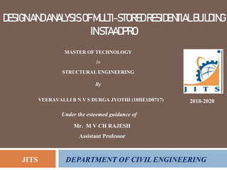
  • 1. DESIGNANDANALYSISOFMULTI-STOREDRESIDENTIALBUILDING INSTAADPRO 2018-2020 Under the esteemed guidance of Mr. M V CH RAJESH Assistant Professor JITS DEPARTMENT OF CIVIL ENGINEERING MASTER OF TECHNOLOGY In STRUCTURAL ENGINEERING By VEERAVALLI B N V S DURGA JYOTHI (18HE1D8717)
  • 2. ABSTRACT The principle objective of this project is to analyze and design a multi-storeyed building [G + 21 (3 dimensional frame)] using STAAD Pro. The design involves load calculations manually and analyzing the whole structure by STAAD Pro. The design methods used in STAAD-Pro analysis are Limit State Design conforming to Indian Standard Code of Practice. STAAD.Pro features a state-of-the-art user interface, visualization tools, powerful analysis and design engines with advanced finite element and dynamic analysis capabilities. From model generation, analysis and design to visualization and result verification, STAAD.Pro is the professional’s choice. Initially we started with the analysis of simple 2 dimensional frames and manually checked the accuracy of the software with our results. The results proved to be very accurate.
  • 3. INTRODUCTION Our project involves analysis and design of multi-storeyed [G + 21] using a very popular designing software STAAD Pro. We have chosen STAAD Pro because of its following advantages: • easy to use interface, • conformation with the Indian Standard Codes, • versatile nature of solving any type of problem, • Accuracy of the solution.
  • 4. LOADS CONSIDERED : 1. DEAD LOADS 2. IMPOSED LOADS 3. WIND LOADS Design Wind Speed (V): The basic wind speed (V,) for any site shall be obtained from and shall be modified to include the following effects to get design wind velocity at any height (V,) for the chosen structure: a) Risk level b) Terrain roughness, height and size of structure; and c) Local topography. It can be mathematically expressed as V = Vb * kl * k* ks Vb = design wind speed at any height z in m/s kl = probability factor (risk coefficient) k = terrain, height and structure size factor ks = topography factor
  • 5. Risk Coefficient (kI Factor): gives basic wind speeds for terrain Category 2 as applicable at 10 m above ground level based on 50 years mean return period. In the design of all buildings and structures, a regional basic wind speed having a mean return period of 50 years shall be used. Terrain, Height and Structure Size Factor (k, Factor): Terrain - Selection of terrain categories shall be made with due regard to the effect of obstructions which constitute the ground surface roughness. The terrain category used in the design of a structure may vary depending on the direction of wind under consideration. Wherever sufficient meteorological information is available about the nature of wind direction, the orientation of any building or structure may be suitably planned. Topography (ks Factor) - The basic wind speed Vb takes account of the general level of site above sea level. This does not allow for local topographic features such as hills, valleys, cliffs, escarpments, or ridges which can significantly affect wind speed in their vicinity. The effect of topography is to accelerate wind near the summits of hills or crests of cliffs, escarpments or ridges and decelerate the wind in valleys or near the foot of cliff, steep escarpments, or ridges.
  • 6. WIND PRESSURES AND FORCES ON BUILDINGS/STRUCTURES: The wind load on a building shall be calculated for: a) The building as a whole, b) Individual structural elements as roofs and walls, and c) Individual cladding units including glazing and their fixings. Pressure Coefficients - The pressure coefficients are always given for a particular surface or part of the surface of a building. The wind load acting normal to a surface is obtained by multiplying the area of that surface or its appropriate portion by the pressure coefficient (C,) and the design wind pressure at the height of the surface from the ground. F= (Cpe – Cpi).A.Pd Where, Cpe = external pressure coefficient, Cpi = internal pressure- coefficient, A = surface area of structural or cladding unit, and Pd = design wind pressure element
  • 7. SEISMIC LOAD  Design Lateral Force  Design Seismic Base Shear  Fundamental Natural Period  Distribution of Design Force  Dynamic Analysis  Time History Method  Response Spectrum Method
  • 8. WORKING WITH STAAD.Pro: Input Generation: The GUI (or user) communicates with the STAAD analysis engine through the STD input file. That input file is a text file consisting of a series of commands which are executed sequentially.
  • 9. Types of Structures: A STRUCTURE can be defined as an assemblage of elements. STAAD is capable of analyzing and designing structures consisting of frame, plate/shell and solid elements. Almost any type of structure can be analyzed by STAAD. A SPACE structure, which is a three dimensional framed structure with loads applied in any plane, is the most general. A PLANE structure is bound by a global X-Y coordinate system with loads in the same plane. A TRUSS structure consists of truss members which can have only axial member forces and no bending in the members. A FLOOR structure is a two or three dimensional structure having no horizontal (global X or Z) movement of the structure [FX, FZ & MY are restrained at every joint].
  • 10. Generation of the structure The structure may be generated from the input file or mentioning the co-ordinates in the GUI. The figure below shows the GUI generation method.
  • 11. Material Constants: The material constants are: modulus of elasticity (E); weight density (DEN); Poisson's ratio (POISS); co-efficient of thermal expansion (ALPHA), Composite Damping Ratio, and beta angle (BETA) or coordinates for any reference (REF) point. G = 0.5 x E/ (1 + POISS) Supports: Supports are specified as PINNED, FIXED, or FIXED with different releases (known as FIXED BUT). A pinned support has restraints against all translational movement and none against rotational movement. In other words, a pinned support will have reactions for all forces but will resist no moments. LOADS: Loads in a structure can be specified as joint load, member load, temperature load and fixed-end member load. STAAD can also generate the self-weight of the structure and use it as uniformly distributed member loads in analysis. Any fraction of this self weight can also be applied in any desired direction.
  • 12. Member load: Three types of member loads may be applied directly to a member of a structure. These loads are uniformly distributed loads, concentrated loads, and linearly varying loads (including trapezoidal).
  • 13. Area/floor load: Many times a floor (bound by X-Z plane) is subjected to a uniformly distributed load. It could require a lot of work to calculate the member load for individual members in that floor. However, with the AREA or FLOOR LOAD command, the user can specify the area loads (unit load per unit square area) for members. Fixed end member load: Load effects on a member may also be specified in terms of its fixed end loads. These loads are given in terms of the member coordinate system and the directions are opposite to the actual load on the member. Load Generator – Moving load, Wind & Seismic: Load generation is the process of taking a load causing unit such as wind pressure, ground movement or a truck on a bridge, and converting it to a form such as member load or a joint load which can be then be used in the analysis. Moving Load Generator: This feature enables the user to generate moving loads on members of a structure. Moving load system(s) consisting of concentrated loads at fixed specified distances in both directions on a plane can be defined by the user.
  • 14. Seismic Load Generator: The STAAD seismic load generator follows the procedure of equivalent lateral load analysis. It is assumed that the lateral loads will be exerted in X and Z directions and Y will be the direction of the gravity loads. Wind Load Generator: The STAAD Wind Load generator is capable of calculating wind loads on joints of a structure from user specified wind intensities and exposure factors. Different wind intensities may be specified for different height zones of the structure.  Design Parameters  Beam Design:  Design for Flexure  Design for Shear  Column Design
  • 15.  General Comments:  Allowable Stresses  Multiple Analyses  Post Processing Facilities  Stability Requirements  Deflection Check  Code Checking
  • 16. ANALYSIS OF G + 21 RCC FRAMED BUILDING USING STAAD.Pro plan of the G+21 storey building All columns = 0.50 * 0.50 m (until ground floor) Columns at the ground floor: 0.8 * 0.8 m All beams = 0.3 * 0.5 m All slabs = 0.20 m thick Terracing = 0.2 m thick avg. Parapet = 0.10 m thick RCC
  • 17. elevation of the G+21 storey building
  • 18. Physical parameters of building: Length = 4 bays @ 5.0m = 20.0m Width = 3 bays @ 5 m =15.0m Height = 4m + 21 storeys @ 3.3m = 73.3m (1.0m parapet being non- structural for seismic purposes, is not considered of building frame height) Live load on the floors is 2kN/m2 Live load on the roof is 0.75kN/m2 Grade of concrete and steel used: Used M30 concrete and Fe 415 steel
  • 19. Generation of member property Generation of member property can be done in STAAD.Pro by using the window as shown above. The member section is selected and the dimensions have been specified. The beams are having a dimension of 0.5 * 0.3 m and the columns are having a dimension of 0.8 * 0.8 m at the ground floor and at the other top floors they are having a dimension of 0.5 * 0.5 m.
  • 20. Supports: The base supports of the structure were assigned as fixed. The supports were generated using the STAAD.Pro support generator. Materials for the structure: The materials for the structure were specified as concrete with their various constants as per standard IS code of practice. fixing supports of the structure
  • 21. Loading: primary load cases input window of floor load generator load distribution by trapezoidal method
  • 22. structure under DL from slab structure under live load
  • 23. Wind load: The wind load values were generated by the software itself in accordance with IS 875. Under the define load command section, in the wind load category, the definition of wind load was supplied. The wind intensities at various heights were calculated manually and feed to the software. Based on those values it generates the wind load at different floors. Height [h] Design wind Design wind speed [Vz] pressure [Pz] Up to 10 m 36.379 m/s 0.793 KN/sq m 15 m 38.85 m/s 0.905 KN/sq m 20 m 40.51 m/s 0.984 KN/sq m 30 m 42.58 m/s 1.087 KN/sq m design wind pressure at various heights
  • 24. wind load effect on structure elevation and plan
  • 25. Floor Wi (KN) Hi(m) Hi2 Wi hi2 *103 (Wi hi2 Along x direction Along Y direction level )/∑(Wi Qix Storey Qiy Storey hi2) shear shear 22 4129 73.3 5372.89 22184662.81 .123 426.309 372.15 21 4252 70 4900 20834800 .115 398.58 824 347.95 372.1 20 4252 66.7 4448.89 18916680.28 .105 363.9 1188 317.69 720.1 19 4252 63.4 4019.56 17091169.12 .0949 328.91 1517 272.3 1037 18 4252 60.1 3612.01 15358266.52 .085 294.60 1812 257.18 1310 17 4252 56.8 3226.24 13717972.48 .076 263.41 2075 229.95 1567 16 4252 53.5 2862.25 12170287 .067 232.2 2307 202.7 1797 15 4252 50.2 2520.04 10717972.18 .059 204.48 2512 178.5 1999 14 4252 46.9 2199.61 9352741.72 .0519 179.88 2692 157.03 2178 13 4252 43.6 1900.26 8082881.92 .044 152.50 2844 133.12 2335 12 4252 40.3 1624.09 6905630.68 .0383 132.74 2977 115.88 2468 11 4252 37 1369 5820988 .032 110.90 3110 96.82 2584 10 4252 33.7 1135.69 4828953.88 .0268 92.80 3221 81.08 2665 9 4252 30.4 924.16 3929528.32 .021 72.78 3314 63.53 2729 8 4252 27.1 734.41 3122711.32 .017 58.92 3386 51.43 2780 7 4252 23.8 566.41 2408502.88 .013 45.05 3445 39.33 2831 6 4252 20.5 420.25 1786903 .0099 34.31 3490 29.95 2871 5 4252 17.2 295.84 1257911.68 .0069 23.91 3525 20.87 2901 4 4252 13.9 193.21 821528.92 .0045 15.59 3549 13.61 2922 3 4252 10.6 112.36 477754.72 .0026 9.01 3564 7.866 2935 2 4252 7.3 53.29 226589.08 .00125 4.33 3573 3.782 2943 1 4505 4 16 72080 .0004 1.38 3577 1.210 2947 total 3579 2948 vertical distribution of earthquake forces to different floor levels
  • 26. seismic load definition structure under seismic load
  • 27. Load combination: The structure has been analyzed for load combinations considering all the previous loads in proper ratio. In the first case a combination of self-weight, dead load, live load and wind load was taken in to consideration. In the second combination case instead of wind load seismic load was taken into consideration. under combination with wind load under combination with seismic load
  • 28. GUI showing the analyzing window
  • 29. DESIGN OF G + 21 RCC FRAMED BUILDING USING STAAD.Pro The structure was designed for concrete in accordance with IS code. The parameters such as clear cover, Fy, Fc, etc were specified. The window shown below is the input window for the design purpose. Then it has to be specified which members are to be designed as beams and which member are to be designed as columns. input window for design purpose. design specifications in STAAD.Pro
  • 30. ANALYSIS AND DESIGN RESULTS TOP 1714.02 0.00 273.43 1691.96 3487.90 REINF. (Sq. mm) (Sq. mm) (Sq. mm) (Sq. mm) (Sq. mm) BOTTOM 3487.98 1692.06 293.58 273.43 1713.94 REINF. (Sq. mm) (Sq. mm) (Sq. mm) (Sq. mm) (Sq. mm) Some of the sample analysis and design results have been shown below for beam number 149 which is at the roof level of 1st floor. 7.1 B E A M N O. 149 D E S I G N R E S U L T S M30 Fe415 (Main) Fe415 (Sec.) LENGTH: 5000.0 mm SIZE: 500.0 mm X 300.0 mm COVER: 25.0 mm SUMMARY OF REINFORCEMENT AREA (Sq.mm) ---------------------------------------------------------------------------------------------------------------- SECTION 0.0 mm 1250.0 mm 2500.0 mm 3750.0 mm 5000.0 mm ---------------------------------------------------------------------------------------------------------------- ---------------------------------------------------------------------------------------------------------------
  • 31. Geometry of beam no. 149 Property of beam no. 149
  • 32. Shear bending of beam no. 149 Deflection of beam no. 149
  • 33. Concrete design of beam no. 149
  • 34. POST PROCESSING MODE post processing mode in STAAD.Pro bending in Z
  • 35. The stress at any point of any member can be found out in this mode. The figure below depicts a particular case. shear stress at any section
  • 36. graph for shear force and bending moment for a column
  • 37. CONCLUSION STAAD PRO has the capability to calculate the reinforcement needed for any concrete section. The program contains a number of parameters which are designed as per IS: 456(2000). Beams are designed for flexure, shear and torsion. Design for Flexure: Maximum sagging (creating tensile stress at the bottom face of the beam) and hogging (creating tensile stress at the top face) moments are calculated for all active load cases at each of the above mentioned sections. Each of these sections are designed to resist both of these critical sagging and hogging moments. Where ever the rectangular section is inadequate as singly reinforced section, doubly reinforced section is tried. Design for Shear: Shear reinforcement is calculated to resist both shear forces and torsional moments. Shear capacity calculation at different sections without the shear reinforcement is based on the actual tensile reinforcement provided by STAAD program. Two-legged stirrups are provided to take care of the balance shear forces acting on these sections.
  • 38. Beam Design Output: The default design output of the beam contains flexural and shear reinforcement provided along the length of the beam. Column Design: Columns are designed for axial forces and biaxial moments at the ends. All active load cases are tested to calculate reinforcement. The loading which yield maximum reinforcement is called the critical load. Column design is done for square section. Square columns are designed with reinforcement distributed on each side equally for the sections under biaxial moments and with reinforcement distributed equally in two faces for sections under uni-axial moment. All major criteria for selecting longitudinal and transverse reinforcement as stipulated by IS: 456 have been taken care of in the column design of STAAD.