1. 1
Extract Technology Delivers State-of-the-Art
Sampling Facility to Big Pharma Company
Updating a Sampling Area
with New Containment
Technology
Gary Partington
Technical Sales Manager
Extract Technology
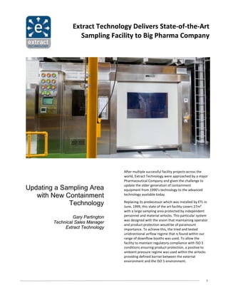
After multiple successful facility projects across the
world, Extract Technology were approached by a major
Pharmaceutical Company and given the challenge to
update the older generation of containment
equipment from 1990’s technology to the advanced
technology available today.
Replacing its predecessor which was installed by ETL in
June, 1999, this state of the art facility covers 27m²
with a large sampling area protected by independent
personnel and material airlocks. This particular system
was designed with the vision that maintaining operator
and product protection would be of paramount
importance. To achieve this, the tried and tested
unidirectional airflow regime that is found within our
range of downflow booths was used. To allow the
facility to maintain regulatory compliance with ISO 5
conditions ensuring product protection, a positive to
ambient pressure regime was used within the airlocks
providing defined barrier between the external
environment and the ISO 5 environment.
2. 2
Rigid Barrier Screen within Facility
Technical process
The Sampling Booth operates with a single pass airflow
regime whereby a clean vertical laminar airflow is
supplied at a velocity of 0.5m/s +/- 10% directly into
the top plenum. After the air has passed over the
operators alleviating any airborne particulate from
their breathing zone, it will be exhausted via the low
level exhaust duct. In addition to the low level
extraction a high level exhaust duct was also
integrated into the rear bulkhead of the booth - this
allowed any particulate at working height to also be
removed from the internal environment. This specific
project housed a local HVAC system which was used to
supply the purified air to both the sampling booth and
airlocks.
Challenged with providing an OEL of less than 1µg/m³
over the task duration, it was decided to integrate a
Rigid Barrier Screen technology into the facility. The
assembly is fitted with a transparent acrylic screen that
houses two glove ports. To ensure ergonomic viability
the screen is mounted on an articulating arm allowing
5 axis of movement. Nevertheless, to achieve the
required OEL of less than 1µg/m³ over the task
duration, set SOP’s (Standard Operating Procedures) of
the screen must be strictly adhered to. The operator
must work behind the acrylic screen through the glove
ports; by doing this a physical barrier is created to
segregate the operator from the product yet still
allowing access to perform their tasks.
The sampling facility housed a sophisticated control
system which allowed for complex and specific
manipulation of the equipment. The on-board PLC
gives signals to the air handling unit informing the unit
at what speed it should be supplying the air to aid in
maintaining the required velocity in various filter
Facility Local Operator Panel
conditions. On-board hardware and systems such as
valves, alarms and the operational sequence of the
facility are all accessible by the integrated HMI. In
addition to the PLC, the facility was fitted with a chart
recorder allowing it to comply with CFR 21 Part 11
regulations. A multitude of monitoring is performed
continuously by various on-board sensors, processed
by the PLC and displayed on the HMI. The monitored
parameters include: booth supply flow, filtration
condition, booth exhaust flow, booth pressure,
oxygen levels, personnel and material airlock
pressure.
A hazardous analysis report supplied by the customer
provided the required ATEX zoning. The unit was
commissioned with both a dust and gas rating with: a
300mm zone around the product was rated to ATEX
Zone 2 IIB T4 and within the exhaust ducts a rating of
Zone 22 IIIB T4.
3. 3
Material Airlock Featuring Client’s Transportation Device
Operational Process
To correctly, safely and efficiently use the sampling
facility the following SOP’s (Standard Operating
Procedures) are utilized:
• Operator starts the facility via the HMI located
outside the airlocks.
• To ensure the facility is in good health all measured
parameters are checked.
• Pallet is placed on rail track transport truck.
• Operator activates external material airlock roller
shutter door (door opened)
• Operator remotely drives the truck into the
material airlock, following the truck into the airlock
to perform the clean down procedures.
• Once preformed the operator exits the material
airlock and de-activates the external roller shutter
door (door closed)
Note: clients transport truck will remain in the material
airlock until the set working pressure is once again
achieved.
• Operator enters personnel airlock.
• Changing procedures take place.
• Operator exits the personnel airlock and enters the
sampling booth.
• Once again the condition of the booth is checked
via the internal magnehelic gauges to ensure
containment is being achieved.
• After this the operator then activates the internal
material airlock roller shutter door. (Door opened)
• The transport truck is driven in via the operator’s
remote control unit.
• Once in place the operator de-activates the roller
shutter door (Door Closed)
• Utilizing the installed work bench and rigid barrier
screen, the operator begins their samplings tasks.
4. 4
Front View of Facility 1
Benefits
• ISO 5 processing conditions
• cGMP finish
• Ergonomic workflow
• Turnkey package
• Custom design to suit client’s process
• Hazardous compliance
• Internal furnishings
• Battery backup LED lighting in airlocks
• PLC control with touch screen HMI interface
• Rapid roller shutter doors for material entry/exit
• Single Pass airflow for liquids/powder handling,
complete with full air handling packages
• Cascading pressure regime
Conclusion
Close collaboration with the customer ensured that the
equipment was engineered to suit their specific needs
and safety requirements. The advanced technology
integrated into the facility provided a more efficient
way to handle highly potent substances. By using a PLC
control system and various conditions monitoring safe
24 hour production within the facility was made
possible, allowing the customer to increase their
production rate without the risk of faulty machinery
compromising the ISO 5 processing conditions.
Learning from previous experience, Extract
Technology were able to add onto the innovative and
educational values of the new facility project.
Although the previous facility was decommissioned
and removed, having its presence on site for 15 years
re-assured the customer that undertaking projects
with Extract Technology will lead to a successful
long term solution.