
Recommended
More Related Content
Similar to Fracture distribution.ppt
Similar to Fracture distribution.ppt (20)
More from SaadTaman
More from SaadTaman (20)
Recently uploaded
Recently uploaded (20)
Fracture distribution.ppt
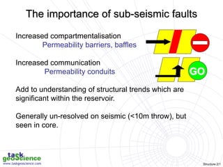
- 1. Structure 2/1 Increased compartmentalisation Permeability barriers, baffles Increased communication Permeability conduits Add to understanding of structural trends which are significant within the reservoir. Generally un-resolved on seismic (<10m throw), but seen in core. GO The importance of sub-seismic faults
- 2. Structure 2/2 Data processing Quality control Fracture effect on flow • Visual appearance • Match with direct/indirect flow indicators Fracture distribution • Raw fracture density • Corrected fracture density • Fracture spacing • Fracture distribution statistics Image description • Fracture identification • Classification • Orientation • Additional attributes Upscaling/prediction • Damage zone widths • Recognition of seismic and subseismic scale faults • Relationship to major structures FRACTURED RESERVOIR MODELLING Raw image log data Core Log data Stratigraphy Seismic sections and maps Core Mudloss Sonic waveforms Dynamic data Stage 1 Stage 2 Stage 3 Fracture interpretation workflow
- 3. Structure 2/3 Images & core Fracture model Reservoir simulation mapped seismic faults Cemented Partially cemented; vuggy Closed Mudstone shear Open Unlithified breccia Cement fault seals Phyllosilicate fault seals Cataclastic fault seals Cataclastic Fracture types and properties The impact of images
- 4. Structure 2/4 Which fractures might be imaged?
- 5. Structure 2/5 A fracture will be imaged if… • It is broader than the minimum intrinsic tool resolution • It has sufficiently contrasting properties compared to the host rock; density and/or textural contrast for acoustic tools and resistivity contrast for electrical tools • Due to the presence of a mineral infill, reduction in grain size and/or preferential cementation around closed fractures • Due to the difference in properties between the drilling fluid and the host rock across open fractures • It is intersected by the borehole
- 6. Structure 2/6 Resolving fractures • Function of tool sample rate • Sensor size (electrical tools) • Beam spot size (acoustic tools) • For electrical images operating under ideal conditions, resolution approaches button size. • Current distortion by strong contrast features has the following effects:- • Features below the intrinsic tool resolution down to around 10 μm may dominate the pixel response of a sample and therefore be detected but their true width and location within the image pixel is unresolved • Conductive fractures draw in current and so appear larger than they really are, with a resistive halo surrounding the fracture • Conductive fractures have a greater depth of penetration than the surrounding matrix and so may be steeper than they appear from images • Resistive fractures repel current and so appear smaller than they really are • These issues may be reduced by running acoustic and electrical tools together (STAR-CBIL and Earth Imager-CBIL)
- 7. Structure 2/7 Fracture sampling by well bore Map view Plan view
- 8. Structure 2/8 Direct measurements and observations from borehole images
- 9. Structure 2/9 Fracture description from borehole images Direct measurements and observations • Location of fracture, measured depth • Fracture attitude as dip and dip direction • Fracture category based on characteristics listed below • Interpretation confidence • Tool response: resistive/conductive if microresistivity, high/low amplitude and long/short transit time if acoustic. • Morphology, e.g. irregular, vuggy, etc. • Continuity: continuous, terminates within borehole, discontinuous within borehole (discrete segments), etc. • Apparent aperture & thickness • Relationship to bedding and other fractures: cross-cutting relationships, offsets, terminations, intersection orientations
- 10. Structure 2/10 Terminology Fracture Natural Induced Fault Microfault Joint Failure plane accommodating strain resulting from tectonism, thermal stresses, compaction, etc. Present in the pristine, formation and relating to geological phenomena Formed in response to drilling operations and not geological Fracture with no offset of wall rocks and often due to dilation Fracture with shear offset displacing hanging- and foot-walls Occasionally used to denote faults with a small offset on a centimetre scale
- 11. Structure 2/11 Fracture categories Descriptive schemes • Response only high, amplitude fracture • Response and offset resistive microfault • Response, offset and morphology discontinuous low-amplitude fracture thick continuous conductive fracture Interpretive schemes • Inferred aperture (caution!) thick open fracture, cemented fracture • Geological interpretation (following core calibration) granulation seam, vuggy fracture FIT FOR PURPOSE
- 12. Structure 2/12 Fracture description exercise – part 1 10 mins
- 13. Structure 2/13 Resistive fault Resistive fracture Conductive fractures Resistive fractures? M M Continuous Irregular trace Width mm-cm? Offset circa 8-10 cm Splays (riedel/antiriedel?) No displacement Hairline Regular trace (planar) Discontinuous Terminates at fault Discontinuous Layer-bound? Form connected network Variable width Weak fabric Resistive Fracture description
- 14. Structure 2/14 Fracture morphologies in a carbonate reservoir Luthi, 2000 Planar Variable width ‘blebs’ Bedding- confined Wide conductive Breccia
- 15. Structure 2/15 • Resistivity images in a water-based mud system (traditional): • Conductive (dark image) =/= open? • Resistive (light) =/= closed? • Resistivity images in an oil-base mud system (new tools; Earth Imager, OBMI): • Conductive (dark image) =/= closed? • Resistive (light) =/= open? • Acoustic Images: • Low amplitude (dark) =/= open? Check transit time image to confirm aperture • high amplitude (light) =/= closed? • Core calibration should be used to confirm type. • Image logs can provide an interpretive insight only. • Only dynamic data provide true insight into fracture “producibility”. Open versus closed
- 16. Structure 2/16 Cemented Partially cemented; vuggy Closed Mudstone shear Open Unlithified breccia Cement fault seals Phyllosilicate fault seals Cataclastic fault seals Cataclastic Cemented Cemented Partially cemented; vuggy Partially cemented; vuggy Closed Closed Mudstone shear Mudstone shear Open Open Unlithified breccia Unlithified breccia Cement fault seals Cement fault seals Phyllosilicate fault seals Phyllosilicate fault seals Cataclastic fault seals Cataclastic fault seals Cataclastic Cataclastic This needs local calibration to core! Fracture Microfault Fault Resistive FRAC RES MF RES FAULT RES Mixed FRAC MIX MF MIX FAULT MIX Conductive FRAC CON MF CON FAULT CON Fracture classification schemes
- 17. Structure 2/17 The importance of ground-truthing Resistive fracture swarm Braided – may relate to shear? Strain hardening? Closed? Cemented? Microfaults? Granulation seams Core or outcrop
- 18. Structure 2/18 Flow zone 2 Flow zone 1 Flowmeter data Acoustic images Manual dips Vuggy fracture
- 19. Structure 2/19 3m 2m Cataclastic fracture and microfault
- 20. Structure 2/20 2m 2m Propped? Open and part-open fractures
- 21. Structure 2/21 Conductive, tension gashes Resistive cemented limestone Dissolution seam Stylolite-associated fractures
- 22. Structure 2/22 Flow paths around fractures Resistive fracture Current is repelled away from the fracture. Current-lines at B are compressed, giving elevated resistivity (low current). Current lines at C are more separated, producing a more conductive response. Conductive fracture Current is drawn into the fracture. Current is increased across the fracture, giving a conductive response at b, B and C. The fracture mid point may therefore be higher than the true fracture location
- 23. Structure 2/23 • If fluid is flowing through fractures, then fracture aperture (open width) influences flow rate. Flow rate is proportional to the cube of the aperture • Aperture may be measured and ranked from resistivity images (although conductive fractures might not be open) and acoustic transit time images • Aperture readings may be misleading as fractures may change in width along their trace, be damaged and enlarged at their interface with the borehole wall, and be affected by the effects of mud invasion. Readings vary between the water, oil and gas legs and must be corrected • Aperture does not necessarily correlate with flow as flow requires connected volume rather than isolated fractures 0 mm 0.64 mm 1.27 mm Fracture aperture assessment
- 24. Structure 2/24 b xo b mR cAR W 1 W fracture width /mm A excess conductance (right) Rm mud resistivity Rxo formation resistivity c,b tool-specific constants derived from forward modelling Relationship between fracture width and excess conductance due to the presence of the fracture. dz I z I V A bm z z b e n } ) ( { 1 0 Ve voltage difference across tool Ib button current, fracture Ibm button current, matrix z vertical position 0,n base, top Luthi-Souhaité equation
Editor's Notes
- 1
- 2
- 3
- 5
- 10
- 13
- 15
- 16
- 17
- 18
- 19
- 20
- 21
- 23
- 24