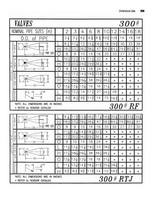
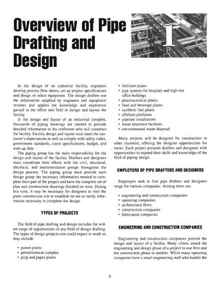
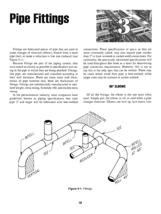
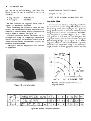
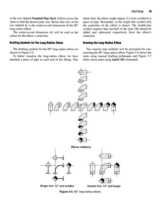
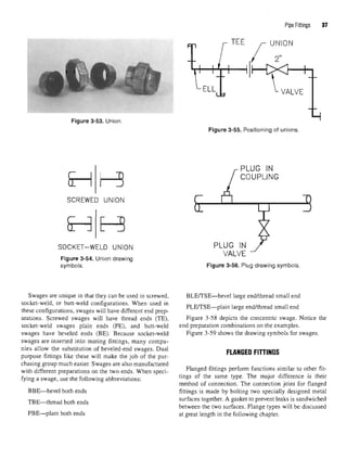
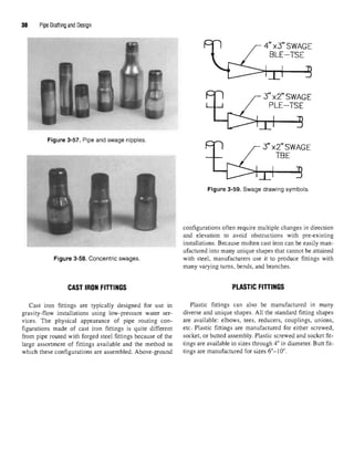
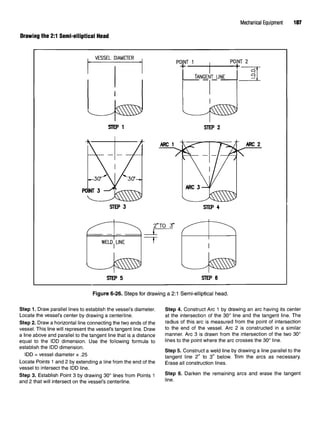
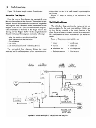
This chapter provides an overview of pipe drafting and design. Pipe drafters and designers work for engineering, construction, operating, and architectural companies. They are responsible for creating thousands of piping drawings to provide detailed information for constructing industrial facilities like chemical plants, refineries, power plants, and more. Their work requires technical skills in drafting as well as personal skills to collaborate with others on complex projects.


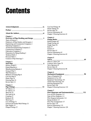

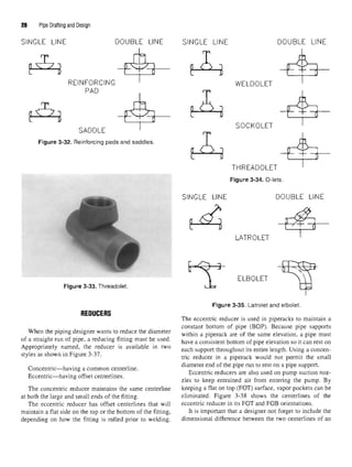

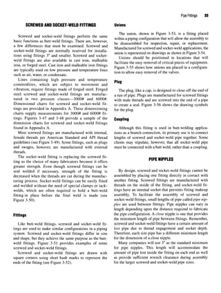
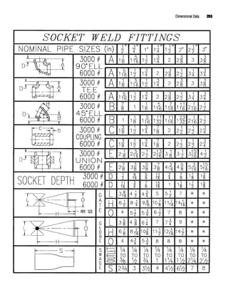
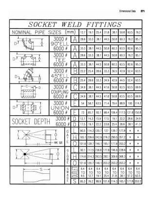
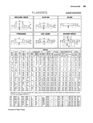
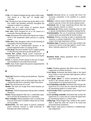
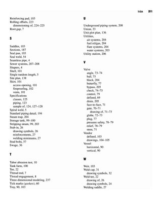
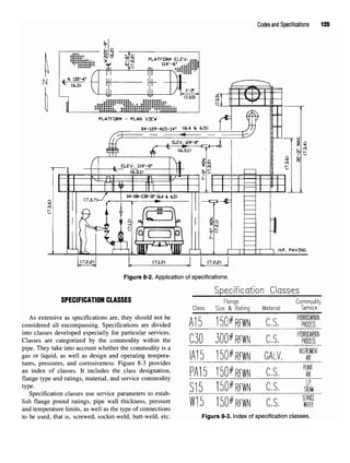
![40 Pipe Drafting and Design
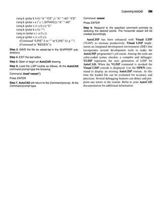
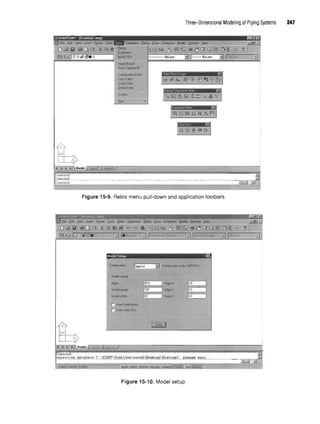
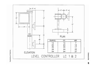
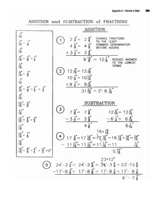
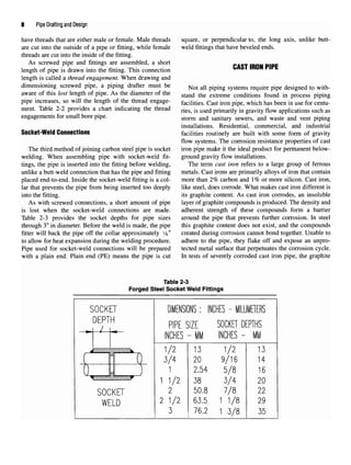
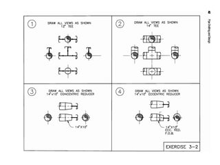
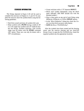
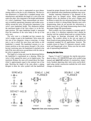
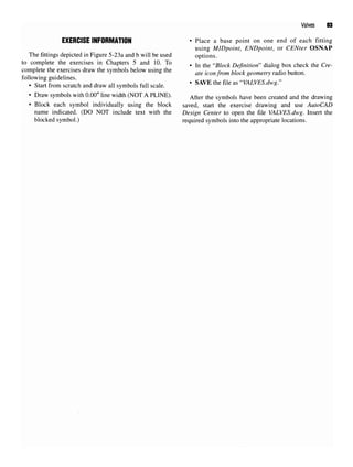
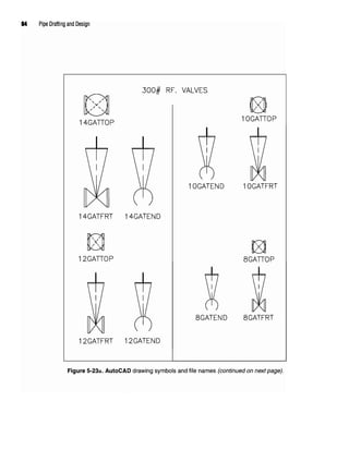
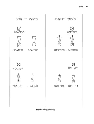
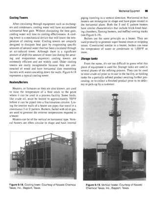
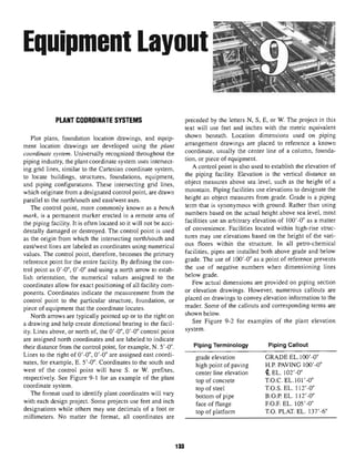
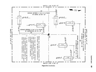
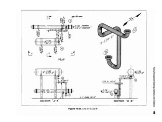
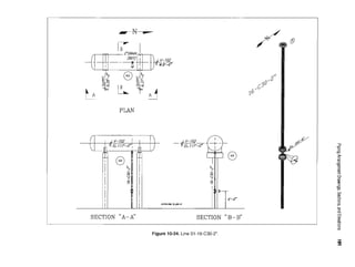
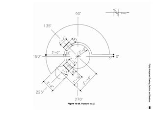
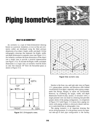
EXERCISE INFORMATION • Place a base point on one end of each fitting using
MIDpoint, ENDpoint, or CENter OSNAP options.
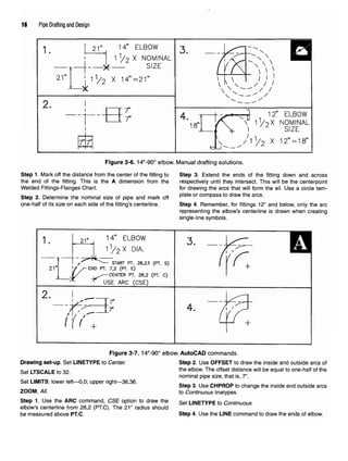
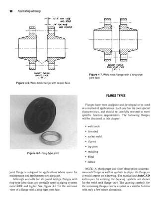
Thefittingsdepicted inFigure 3-60 will be used tocomplete . jn the "Block Definition" dialog box check the
the exercises in Chapters 3,4, 5, and 10.Tocomplete the exer- Create iconfrom block geometry radio button,
cises, drawthe symbolsbelow usingthe followingguidelines. • SAVE the file as "ELBOWS.dwg".
• Start from scratch and draw all symbols full scale.
• Draw symbols with a PLINE having a width of .56" After the
symbols have been created and the drawing
(y]6") for single line symbols and a 0"width for double saved
' start the
exercise drawing and use AutoCAD
line fittings. Symbols requiring a full circular shape must Design Center to open the file ELBOWS.dwg. Insert the
be drawnwiththe PLINE command ARC option. These required symbols into the appropriate locations.
arcs can only be drawnwith a 359° circumference. NOTE: The pipe break symbol is created with ellipses.
• Create weld dots with a 1.75" diameter DONUT. The ma
Jor axis of each
ellipse is equal to one-half ofthe
• Block each symbol individually using the block P1
?6
'8 OD
- TRIM or
BREAK an ellipse to create the
name indicated. (DO NOT include text with the elliptical arc on the pipe break as necessary.
blocked symbol.)
Figure 3-60. AutoCAD drawing symbols and File names.](https://image.slidesharecdn.com/pipedraftinganddesign-220418204530/85/Pipe-drafting-and-Design-pdf-53-320.jpg)
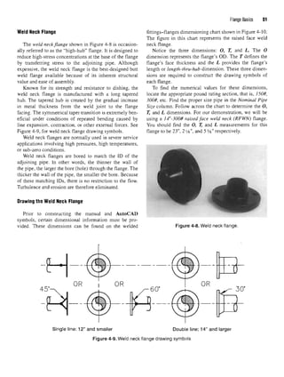
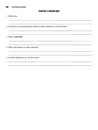
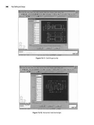
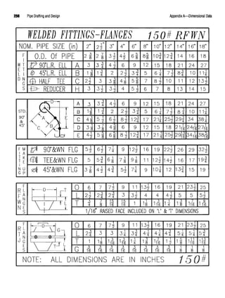
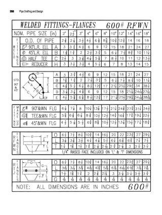
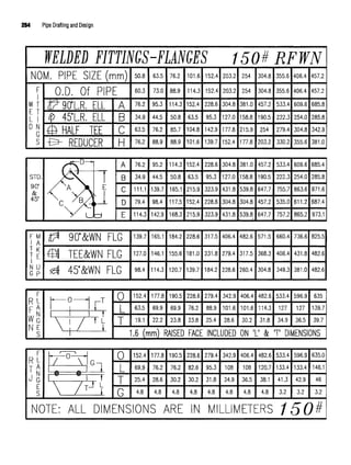
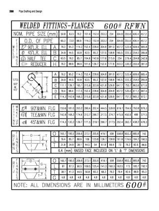
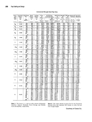
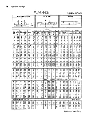
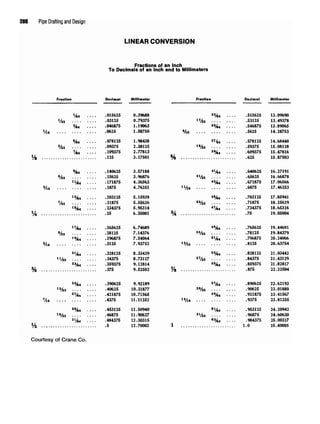
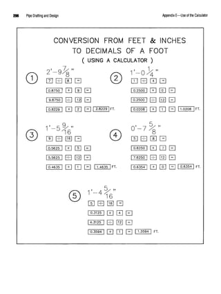
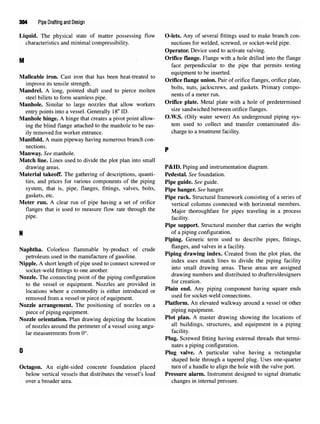
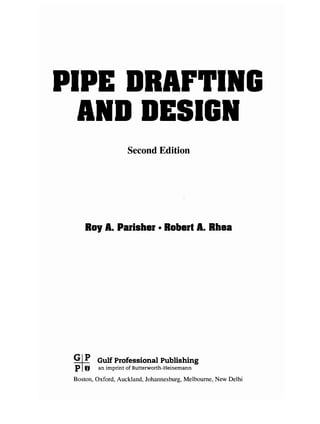
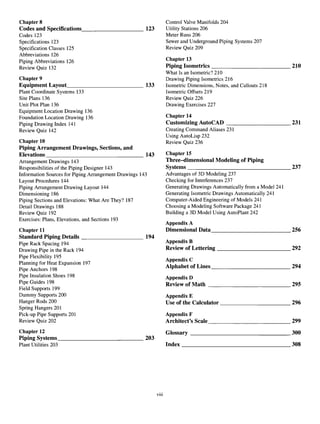
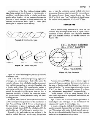
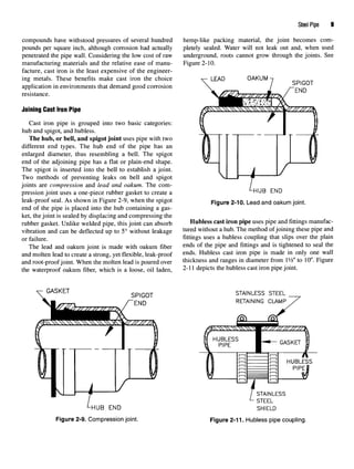
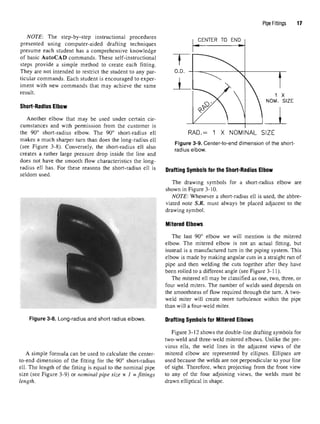
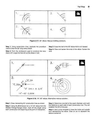
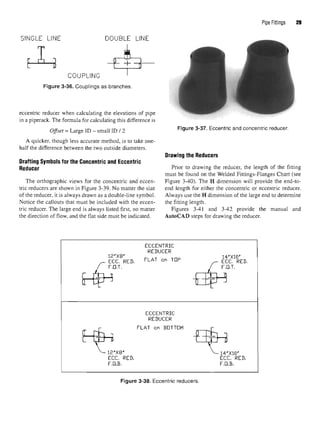
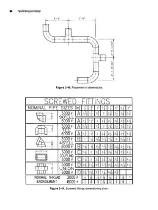
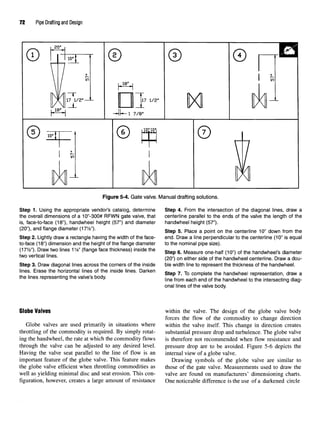
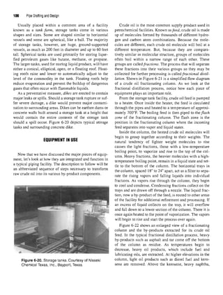
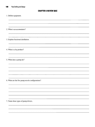
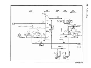
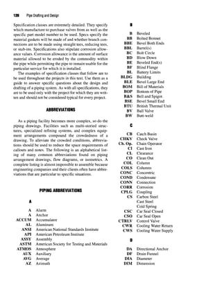
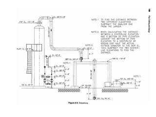
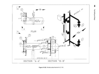
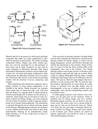
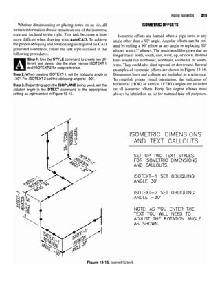
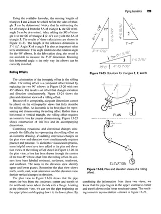
![Flange Basics 53
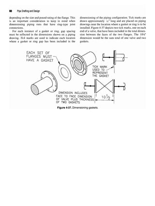
Figure 4-12.14"-300# RFWN flange. AutoCAD commands.
Drawing set-up Step 3. OFFSET the centerline 7" (one-half of the 14" pipe
Set LINETYPE to Continuous OD) above and below the pipe's centerline. CHANGE the
Set LIMITS: lower left corner—(0,0) linetype of these two lines to Continuous.
upper right corner—(10,30) step4 From the rjght end Qf the f|ange> draw 3Qo nnes toward
ZOOM, All the flange face to represent the flange hub. TRIM as required.
Step 1. Draw a vertical LINE 23"tall from 2,4. (This line will ER
*SE cons
'r
^o
:
n
'ines
' Wh
^ C
?n
5"ctir
!?,s]n
9«e-line
represent the flange's face). s
Vmbols
' use PLINEs havin
9aWldth of
'56
<9/16
>fu!l scale or
.0175" when drawing to %" = 1'-0" scale to draw the face
Step 2. Use OFFSET to draw the flange face thickness 21
/8" thickness and hub length. Use a DONUT with a fullscale
toward the right. Close the top and bottom ends. OFFSET inside diameter of 0.000" and an outside diameter of 1.75" as
the flange face line 5%" to the right. (This will establish the a symbol for the weld dot. Weld dots drawn to %" = 1 '-0"
length-thru-hub distance.) From the MIDpoint of the flange scale will have an outside diameter of .05".
face, draw the flange's centerline to the right.
Figure 4-13. Slip-on flange.
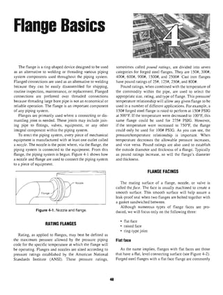
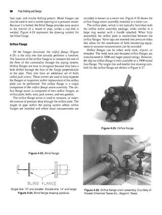
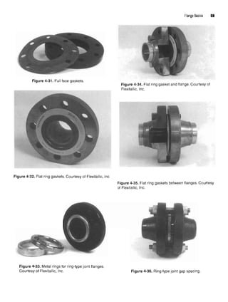
Lap-joint Flange
The lap-joint flange in Figure 4-15 is primarily used on
carbon or low alloy steel piping systems. Attachment of
the lap-joint flange to the piping system requires a lap-
joint stub end. The lap-joint flange and stub end assembly
are used mainly in piping systems that necessitate frequent
dismantling for inspection or routine maintenance. It is
also used in the erection of large diameter or hard-to-
adjust piping configurations because of its quick bolt hole
alignment. Figure 4-16 depicts the drawing symbols for
the lap-joint flange.
Threaded Flange
The threaded flange depicted in Figure 4-17 similar to
the slip-on flange, but the bore is threaded. Its principal
value is that it can be assembled without welding. This
feature makes the threaded flange well-suited to extreme
pressure services that operate at normal atmospheric tem-
peratures and in highly explosive areas where welding
may create a hazard.
Threaded flanges are not suited, however, for condi-
tions involving temperatures or bending stresses of any
significance, particularly when cyclic conditions exist,
which may cause leakage through the threads. After just a
relatively few cycles of expansion and contraction or
movement caused by stress, the threaded flange no longer
performs adequately.](https://image.slidesharecdn.com/pipedraftinganddesign-220418204530/85/Pipe-drafting-and-Design-pdf-66-320.jpg)
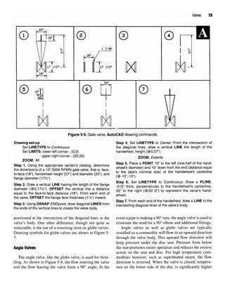
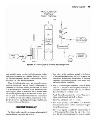
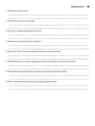

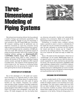
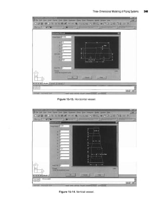
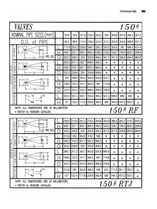
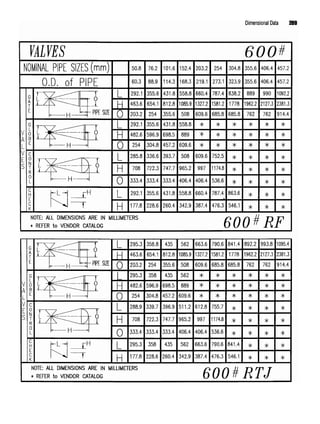
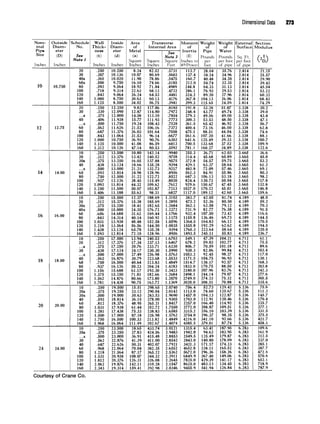
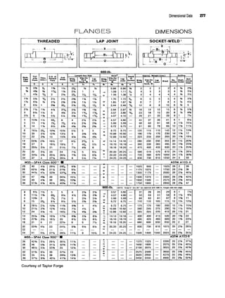
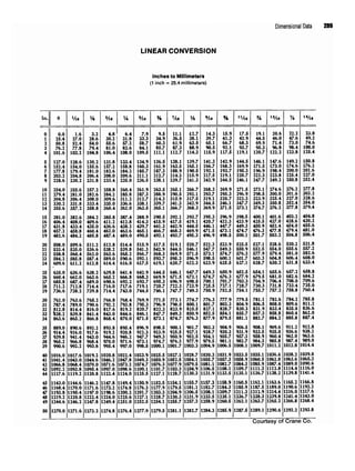
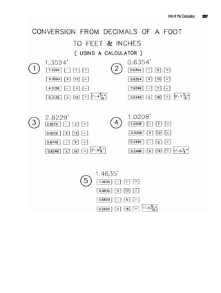
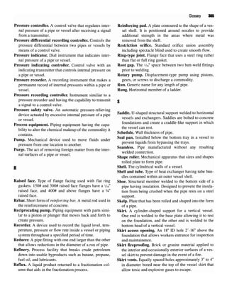
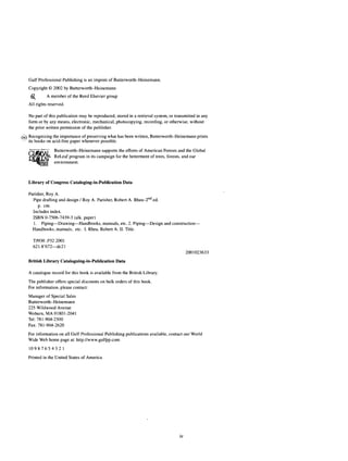
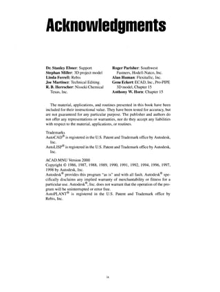
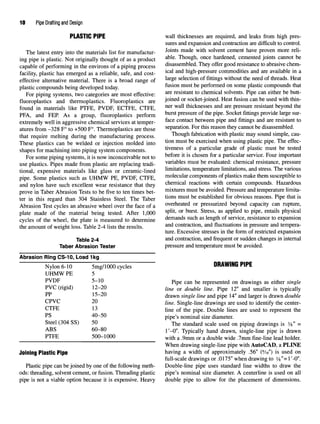
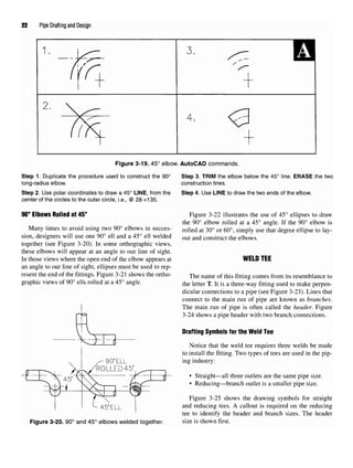
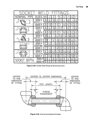
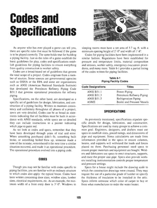
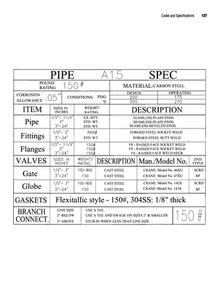
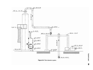
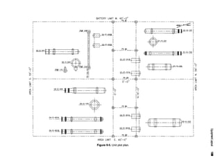
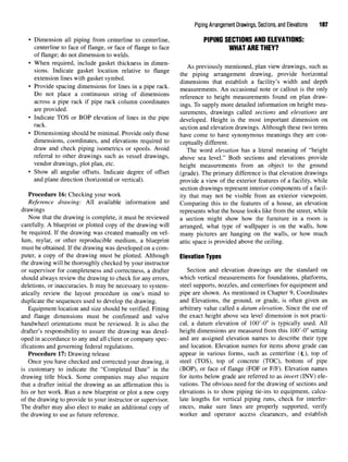
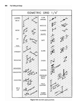
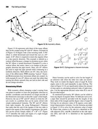
![Flow Diagramsand Instrumentation 119
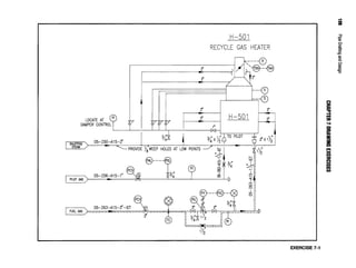
EXERCISE INFORMATION Exercises 1,2, and3
Use the instructions accompanying Figure 7-6 to create Recreate the flow diagrams as shown. Using the
the flow diagram symbols with AutoCAD as shown. Use symbols in Figure 7-6 where applicable. Symbols repre-
the BASE command to place the base point as indicated. senting other pieces of equipment can be developed on an
BLOCK each object using the exact symbol name pro- as-needed basis. Although equipment is not drawn to
vided. OOPS the symbol to redisplay. SAVE the drawing scale, it should be proportional to the other symbols used
as FLOSYMBL. in the drawing.
FLOW SHEET SYMBOLS
TO DRAW FLOW SHEET SYMBOLS SET GRID TO .125 AND SNAP TO .0625
THE .125 GRID SHOWN BELOW HAS BEEN ENLARGED FOR BETTER VISUALIZATIION.
DRAW AND BLOCK EACH SYMBOL. BASE POINT ( '& ) &
SYMBOL NAME [NAME] HAVE BEEN INCLUDED FOR PROPER IDENTIFICATION.
Figure 7-6. Flow diagram exercise symbols.](https://image.slidesharecdn.com/pipedraftinganddesign-220418204530/85/Pipe-drafting-and-Design-pdf-132-320.jpg)


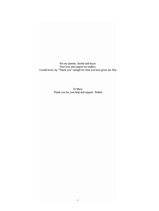
![Customizing AutoCAD 233
effect being realized. Aliases do not allow multiple (defun c:LE ()
parameters to be invoked during the command sequence. (command "LINE" "END")) [draws a LINE seeking
A word of caution here, AutoLISP routines override alias the 'From point:' as an ENDpoini]
commands. If they both have a common name the (defun c:LM ()
AutoLISP routine will be invoked. (command "LINE" "MID")) [draws a LINE seeking
The following step-by-step procedure will explain how the
'From
Point:
' as a
MDpoint}
to create yourfirstLISP routine. (defun c:RED ()
(command "COLOR" "RED")) [sets the new
Step 1. Use a text editor to begin a new file. COLOR value to RED]
NOTE: To better organize files, all new .Isp files you ere- (defun c:WHITE ()
ate should be kept in the same subdirectory as those already (command "COLOR" "WHITE")) [sets the new
existing within AutoCAD. On most versions of AutoCAD COLOR value to WHITE]
.Isp files are kept in the SUPPORT subdirectory. (defun c:BLUE ()
_ ..__ . ..., , . , , ^ (command "COLOR" "BLUE")) [sets the new
The LISP routine we will be develop uses defun state- _^T _„ 7 _r ,.„
. ^ r • f T^n. T^TTVT *• ^ £. COLOR value to BLUE]
ments. Dejun is an acronym for DEfine FUNction. Defun
statements are keyboard inputs that allow an operator to Step 3. S/WEthe file as PIPELISP.Isp.
use short command names to describe longer AutoCAD _. . -.,.-.. . . ...
m , ., .^ Step 4. EX/rthe text editor,
command sequences. The letter name used to identify
your defun statement is the command name that will be Y
°u wil1
probably want to test your LISP routine at this
typed at the keyboard as a replacement for the longer time
- Unlike the ACAD.pgp file, LISP routines must be
AutoCAD command and parameter options. Typing in loaded each time they are to be used in a drawing. Once
the one or two letter command name saves considerable loaded into a drawing, LISP routines become part of that
time when compared to conventional command sequences. drawing during the time it is the current drawing file. If
you end the drawing and open it at a later time the LISP
Step 2. Type the following statements just asthey appear. It .. . u , , , T TCD .• , i A .nt
• / * *u * i- - i - i -j- x XL. routine must be reloaded. LISP routines can be loaded at
is important that you have a good understanding of the , , , , . , , , , , • ,
AutoCAD command you're are wanting to initialize so that the
keyboard using the following command,
no parameter is overlooked. Anynew commands youwant to g< AutoCAD command Qm
develop can be created in the same manner as the ones th f ll ' •
shown below. To help you understand the command being e
° Wl
9-
developed, a short explanation is provided in the brackets Command:(load "PIPELISP")
following each statement. Do not include the explanation in press ENTER
the routine you are developing. Remember, type the state-
ment just as they are shown. Including all opening, closing, The second part of your LISP routine will incorporate
and double parentheses. the flow diagram symbols created in Chapter 1'. As an
NOTE: New versions of AutoCAD have functions that alternative to the AutoCAD Design Center this routine
make these commands seem obsolete. Users of older ver- wil1ex
Pedite the
insertion of symbols that have been pre-
sions however mayfind these commands useful. They are viousl
ymserted mto a
Cawing asblocks. Addthe follow-
intended as samples only. in
g de
^n
statements to the end of your PIPELISP
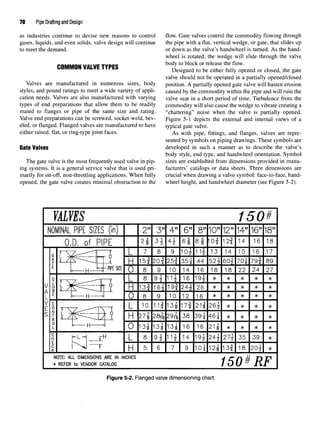
routine.
(defun c:ZE ()
(command "ZOOM" "EXTENTS")) {performs the Step 1. Open the PIPELISP.Isp file using the text editor.
ZOOM command with the EXTENTS option. Keep a step 2. Use the scroll bar to move to the end of the file.
single line space between each 'defun' statement} step 3 Add ^ fo||owing defun statements to the end of
(defun c:ZP () your P|PEL|SP routine,
(command "ZOOM" "PREVIOUS")) {performs the
ZOOM command with the PREVIOUS option} (defun c:PUMP ()
(defun c:LIT () (command "INSERT" "PUMP")) [Keep a single
(command "LINE" "INT")) [draws a LINE seeking line space between each 'defun' statement.]
the 'From point:' as a point of INTersection. LIT was (defun c:EXH ()
chosen as the defun name because LI is the command (command "INSERT" "EXH"))
alias for the LIST command.} (defun c:HOR ()](https://image.slidesharecdn.com/pipedraftinganddesign-220418204530/85/Pipe-drafting-and-Design-pdf-246-320.jpg)
![234 Pipe Drafting and Design
(command "INSERT" "HOR")) Obviously any name can be given to the defun state-
(defun c:VERT () ments to describe the command you want to perform.
(command "INSERT" "VER")) Printing a copy of your routine, once it is complete, may
(defun c:GATE () be necessary to prevent the duplication of names on new
(command "INSERT" "GV")) statements you may add later. This printed copy we also
(defun c:GLOBE () help you remember the new command names you will be
(command "INSERT" "GBV")) using when inserting the symbols or performing com-
(defun c:CONTROL () mands.
(command "INSERT" "CV")) As mentioned previously the second LISP routine is
(defun c:CHECK () much more complex than the first. More than just defun
(command "INSERT" "CKV")) statements, it is written using programming expressions
(defun c:PSV () specific to AutoLISP that will automatically create a hor-
(command "INSERT" "PSV")) izontal vessel and its two head enclosures, including weld
(defun c:ORIFICE () lines. The routine is written in such a manner that the end
(command "INSERT" "OF")) user is allowed to select points within an AutoCAD draw-
(defun ciREDUCER () ing that will specify the vessel's location, length, diame-
(command "INSERT" "RED")) ter, and orientation. Once the user has specified the
(defun c:BUBBLE () required values the routine will calculate and draw the
(command "INSERT" "IB")) vessel,
(defun c:NOZZLE () Follow the steps as indicated below to create the vessel
(command "INSERT" "NOZ")) using AutoLISP language,
(defun c:FLOWARO() st 1 y ^ dj b . f.}
(command "INSERT" "FA")) H y
(defun c'CONTBOX () ^te
P ^- Type the following statements just as they appear.
(command "INSERT" "CB")) Include allopening, closing, and double parentheses,
(princ "Your LISP routine has been loaded!") (defun c: Vessel ()
Step 4. SAVEVne modified file as the same name. (setq s (getpoint "Select starting point on vessel cen-
Step 5. EXIT the text editor. terline:n"))
. , , , , • ^,, -, (se
tq a (getangle s "Select second point to establish
Any symbol that was created in Chapter 7 can be , . . , ,,NN
jj i rror, • ^ r /ror, -n VCSSCl OnentatlOIKVIl ))
added to your LISP routine Before your LISP will prop- . , , , . « « , . ,,. ,
, . . ., . . u i * * (setq 1(getdist Select two points to establish vessel
erly insert the appropriate symbol a fewmore steps must , , e r
u i . A length.
be completed. m ,. ^ , ^ .,. ,. . „.
(Tangent to tangent distance). nSpecify first point. ))
Step 1.Make certain allflow diagram symbols have been ( d ( dist ^ Sdect two ^ to establish
created on the drawing FLOSYMBL and blocked using the , ,. 4
specified names. vessel diameter.
nSpecify first point."))(setq b (+ api))
Step 2. Begin or open the drawing into which the flow dia- / , / -y.
gram symbols are to be inserted. ^ ^
(setq c (/ d 2))
!!e
J?ov;,D
U
,Se th
! INSERT
,C0mmand to insert drawing
(setq e (polar sal))
FLOSYMBL into the current drawing. ] ,
;
; .^
(setq f (/ pi 2))
Step 4. ERASE drawing FLOSYMBL out of the current draw- (seta e (* c 0 7320508))
ing. (Inserting and erasing FLOSYMBL will cause the blocks r*
of that drawing tobecome nested within the current drawing.) ^setqh
^po ar e
^a
*>c
^
(setq hi (polar s (- a f) c))
Step 5. Load your LISP routine if it is notalready loaded. / . • / i / /% ^
(setq j (polar e (+ a f) g))
Command: (load "PIPELISP") (setq j 1 (polar s (- a f) g))
Press ENTER (Command n "PLINE" h "W" "0" "" "A" "CE" j
"A" "-60" "CE"
Step 6. Type in the desired symbol name at the command
prompt. Pick the insertion point as needed, establish the (setq k (polar e b (* c 1.2679492))) "A" "-60"
appropriate X/Y scale factors, androtation angle. (setq k (polar e (- a f) c)) "L"](https://image.slidesharecdn.com/pipedraftinganddesign-220418204530/85/Pipe-drafting-and-Design-pdf-247-320.jpg)