A Review Paper on Concrete Cast In-Situ Bored Piles Cushioned with Mixture of...
Time dependant differential consolidation of slurry wall backfill
1. Time dependant differential consolidation of slurry wall backfill
Rahul V. Mukherjee
University of Saskatchewan, Saskatoon, Canada (rahul.mukherjee@usask.ca)
Moir D.Haug
University of Saskatchewan, Saskatoon, Canada (mhaug@mdhsolutions.com)
ABSTRACT: This paper presents the preliminary results of a laboratory testing program to investigate time-dependant
differential consolidation of slurry wall backfill material. The program was conducted to supplement the design and
installation of an 11,000 m long slurry wall. This slurry wall is installed through intermediate aquifers within low permeable
glacial till to a final depth of nearly 50 m. The testing program involves large diameter large strain consolidation testing of
selected field backfill samples. The apparatus was also modified to measure lateral pressure during loading. The heads
across the large strain consolidation apparatus were measured continuously. These results were supplemented by direct
shear tests performed on the different backfill materials. The results of this program show that there is significant retardation
in vertical stress in the backfill caused by arching. It also shows that the narrower the trench the greater the loss of vertical
effective stress. Future testing and analysis may show that the loss of this stress increases the potential for differential
consolidation around intermediate aquifers.
INTRODUCTION
The potential for slurry wall backfill arching and hang-up
was examined in a laboratory testing program. The
permeability of clay till slurry backfill is highly dependent
on the load placed on the backfill. As a result permeability
usually decreases with depth as the backfill consolidates
slowly under increasingly high loads. If the width of the
backfill trench is narrow and the depth great, there is a
potential for arching and backfill hang-up. In addition, if
the slurry wall crosses multiple aquifers it is possible that
differential consolidation around these aquifers could
result in the creation of more permeable zones with depth.
In order to examine this potential a laboratory program
was conducted to examine large-strain consolidation of
clay-till slurry backfill.
BACKGROUND
Soil bentonite (SB) slurry walls vertical barriers
constructed by excavating a narrow trench through
permeable material or zones and backfilling with a
mixture of soil, bentonite and water to achieve a low
permeability barrier (Xanthakos 1979, Haug 1983, Evans
1995). The soil either comes from the excavated trench or
from a source nearby, if the soil is deemed to be
unsuitable for use. The slurry in the SB wall is a mixture
of water and dry bentonite (4% - 7%) by weight (Evans
1994). Before placement in the trench the backfill is
mixed with desired amount of slurry from the trench to
provide a desired consistency. Since SB walls are mainly
used as low permeability barriers and constructed as a part
of polluted site remediation process, hydraulic
conductivity value plays a very important role. In general,
they range from 10-7
m/s to 10-11
m/s (D’Appolonia 1981,
Haug 1987, Evans 1995, Yeo et al 2005).
The value of permeability for the backfill mixture depends
upon many factors such as (i) the amount of dry bentonite
added to the mix (Ryan 1987, Evan 1994, Yeo et al 2005),
(ii) the amount of fines in the mixture (Xanthakos 1979,
D’Appolonia 1981, Yeo et al 2005), (iii) resistance of the
mix against the contaminant being contained and (iv) the
state of stress in the slurry wall (Evans 1995, Filz
1999).The performance assessment of these walls in terms
of hydraulic behaviour is generally done through
laboratory testing of the backfill mixture.
Laboratory model and field study on the slurry walls have
shown that the stress in the wall does not increase linearly
with depth as assumed earlier (McCandless and Bodocsi
1987, Evans 1995).The friction at the trench/backfill
interface governs the consolidation behaviour of the
backfill-slurry mix, which is fairly compressible. This
phenomenon can be explained by arching mechanism.
THEORY
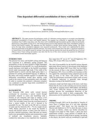
Arching (Terzaghi 1943) can be described as “transfer of
stress from a yielding mass of a soil onto adjoining
stationary parts”. This theory was first described by
Marston and Anderson in 1913 to show the state of stress
on pipes in ditches, which was further described by
Terzaghi in his paper in 1945. Figure 1 shows the force
mobilization around a small element of backfill dh in
thickness in a trench of width B due to arching. According
to this theory, the trench walls are considered as rigid and
2. the backfill material is considered as compressible.
Consolidation and settlement of backfill with time cause
shear stresses to be mobilized along the trench walls (Fig
1), which act as a partial support for the backfill and hence
reduces the effective vertical stress in the trench below the
overburden pressure.
According to static equilibrium conditions, considering
the vertical force equilibrium (∑ FY=0) of the horizontal
slice in Fig1.
(a)
Where,
µ = co-efficient of friction between the trench wall and
backfill
K = co- efficient of earth pressure (ratio of horizontal
stress to vertical stress)
Solving the partial differential equation in (a), we get
V = ) (b)
Computing the average vertical stress from equation b,
σav = = ) (c)
Fig 1: Arching mechanism after (Marston and Anderson, 1913)
FOCUS OF THE STUDY
Backfill hang-up and arching is of particular concern for
deep slurry walls. This potential is a function of the width
of the trench, the depth of the trench, shear strength of the
backfill and potentially the sequence and spacing of
permeable zones cut-off by the slurry wall.
In 2009, construction was started on an 11,000 m long,
over 45 m deep slurry wall through glacial till at a
Saskatchewan potash mine. This slurry wall is intended to
control the migration of chloride impacted water. The
permeability and the potential for osmotic consolidation is
a function of the stress environment of the trench backfill.
As a result, the potential for arching or wall hang-up is a
concern. Further complicating the situation is the presence
of stacked aquifer which will result in more rapid backfill
consolidation at various depths in the trench. Figure 2
shows the site geology.
Fig 2: Schematic diagram of site geology
EXPERIMENTAL PROGRAM
The experimental program involves large strain
consolidation testing of the backfill mixes. A 150 mm
diameter consolidation cell was modified to increase its
depth and fitted with ports (A to E) to enable pore
pressures to be measured. Marriott bottle system was also
used to enable continuous monitoring of permeability
during loading. Miniature load cells were installed on the
walls of the mold at different depth to measure the stress
profile. Figure 3 shows a sketch of the mold.
Direct shear tests were also conducted on the different
backfill mixes to measure their frictional characteristics.
TEST MATERIALS
Till that was used in the experimental study was collected
from the site. Table 1 shows the index properties of the till
and the backfill. Additional backfill mixes were prepared
3. for this study by adjusting the fine content to 10%, 25%
and 50%.
Fig 3: Modified mould
TABLE1. Index properties of Till and clay-till backfill
Property Till Backfill
Specific Gravity 2.72 2.68
Liquid Limit (%) 42.5 37.5
Plastic Limit (%) 24 20
Plasticity Index (%) 18.5 17.5
Gravel (%) 30 20
Sand (%) 40 52
Silt (%) 14.5 19
Clay (%) (<0.002 mm) 15.5 9
TESTS PERFORMED AND TEST PROCEDURE
Direct shear test
Samples from different mix were allowed to consolidate
in large consolidation molds at different specified normal
loads. After, consolidation was complete; the samples
were extruded and trimmed to fit into 150 mm x 150 mm
diameter direct shear box. The samples were left for 1 -3
days depending upon the normal load. The shear box test
was then carried out according to ASTM D-3080-04.
Large strain consolidation and hydraulic conductivity
testing
All the saturated samples in the molds were compacted at
a water content corresponding to a slump of 12 cm and at
a constant dry density. The depths in the field were
simulated corresponding to the load applied onto the
sample. The samples once compacted were left to
consolidate under the weight of the loading plate, till the
load cell and potentiometer reading stabilized. The whole
setup was then loaded using Karol-Warner Conbel. Load
cell and deflection readings were recorded and monitored
continuously. A constant head hydraulic conductivity test
was run simultaneously, with a use of a Marriott bottle
arrangement (Fig 3). Once the equilibrium was attained,
next incremental load was applied to the sample.
DISCUSSION OF TEST RESULTS
Impact of fine content on shear strength
Figure 4 shows the variation of shear strength with
percent of fine in the backfill mix. The bold line
represents the 50% fine content mix and the dotted line
represents the 25% fine mix. The angle of internal friction
was not highly dependent on the % of fine. The friction
angle for these clay-till mixes ranged from 23 to 26
degrees. These values are considerably lower than the 30
to 35 degrees previously reported in the literature.
Fig 4: Shear strength of clay-till backfill
Fig 5: Variation in vertical hydraulic conductivity and
coefficient of lateral earth pressure with calculated depth
4. Figure 5 shows the variation of coefficient of lateral earth
pressure (k) and hydraulic conductivity measured during
one of the large strain consolidation tests. The hydraulic
conductivity decreases. This is because, as the load is
increased the void ratio decreased, gradually with depth,
however the rate of decrease slowed under increased
loads. A sharper decrease was measured for the
coefficient of lateral earth pressure.
Stress distribution in slurry wall
Figure 6 shows the stress distribution profile in deep clay-
till backfilled deep slurry trench with width of 0.6 to 2.1
m using the results of the test program according to
equation (c). The unit weight, coefficient of lateral earth
pressure and shear strength of the backfill are: γ = 17.8
kNm3
, k=0.10 and ϕ = 23.The stress in the backfill is
always less than the geostatic stress (γ`h) and becomes
constant with depth. This is because at large depths, the
shear stresses at the sides of the trench are then large
enough to balance the extra weight of each additional
layer of backfill. However, for any given depth, it is
evident from the figure that with the increase in the width
of the wall, the stress increases.
Fig 6: Stress profile in SB walls
CONCLUSION
The results of this study show that there is a significant
loss of effective vertical stress in the backfill with depth,
and that this loss increases for narrower trench. Future
testing will be required to show if such loss in stress
increases differential consolidation across aquifers. The
hydraulic conductivity of the clay-till backfill was found
to range from 10-5
m/s at a depth of 0.5 m to 10-8
m/s at a
depth of 2m. The hydraulic conductivity was still
decreasing with load. The coefficient of lateral earth
pressure was also found to decrease ranging from near 0.3
near ground surface to 0.1 approaching 2.5 m depth. In the
case of a 1m wide trench only a small proportion of the
backfill weight acts to consolidate backfill at depth.
REFERENCES
ASTM D 3080 – 04. Standard test method for direct shear test of
soils under consolidated drained conditions
D’Appolonia, D. (1980) Soil-bentonite slurry trench cut-offs.
Journal of Geotechnical Engineering Division, 106(4), 399-417.
Evans, J.C., Costa, M.J. and Cooley, B. (1995) The state-of-
stress in soil-bentonite slurry trench cut-off walls, Proc.,
Geoenvironment 2000, ASCE Geotechnical Special Publication
No.46, Y.B. Acar and D.E. Daniel, eds., New Orleans,
Louisiana,1173-1191
Filz, G.M. (1996) Consolidation stresses in soil-bentonite
backfilled trenches, Proc.,Environmental Geotechnics,
Kamon(ed), Balkema,Rotterdam,497-502.
Haug, M.D. (1983) Selection criteria for slurry trench cut-offs.
Canadian Journal of Civil Engg, 10(3),527-537.
Marston, A. and Anderson, A.O. (1913) The theory of loads on
pipes in ditches and tests of cement and clay drain tie and sewer
pipe. Iowa Engineering Experimental station Bulletin (31),
Ames, Iowa.
McCandless, R.M. and Bodocsi, A. (1988) Hydraulic
characteristics of model soil-bentonite slurry cut-off walls. In
Proceedings of the 5th
National Conference on Hazardous
Wastes and Hazardous Materials.
Evans, J.C. 1994. Hydraulic conductivity of vertical cut-off
walls. Hydraulic conductivity and waster contaminant transport
in soil, ASTM STP 1142, D.E. Daniel and S.J Trautwein, eds.,
Chapman and Hall, London,430-454.
Ryan, C.R. 1987. Soil bentonite cut-off walls, Geotechnical
practice for waste disposal’87, R.D Woods, ed., ASCE, New
York, 182-204.
Terzaghi, K. (1945) Stability and stiffness of cellular
cofferdams. Transactions, ASCE, 110(2253), 1083-1119.
Xanthakos, P.P. (1979) Slurry walls, McGraw Hill, New York,
NY.
Yeo, S.S., Shackelford, C.D. and Evans, J.C (2005)
Consolidation and hydraulic conductivity of nine model soil-
bentonite backfills. Journal of Geotechnical and
Geoenvironmental Engineering, 131(10), 1189-1198.