Components of a solar electric generating system
•
1 like•108 views

Solar panel, potential difference , current, voltage.Controller, Batteries, Inverter.

Recommended
More Related Content
What's hot
What's hot (20)
Similar to Components of a solar electric generating system
Similar to Components of a solar electric generating system (20)
More from Dr.Raja R
More from Dr.Raja R (20)
Recently uploaded
Recently uploaded (20)
Components of a solar electric generating system
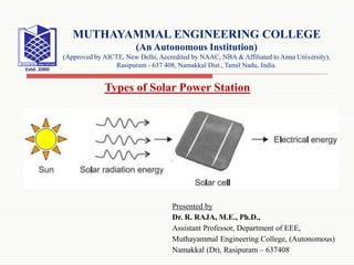
- 1. Presented by Dr. R. RAJA, M.E., Ph.D., Assistant Professor, Department of EEE, Muthayammal Engineering College, (Autonomous) Namakkal (Dt), Rasipuram – 637408 Types of Solar Power Station MUTHAYAMMAL ENGINEERING COLLEGE (An Autonomous Institution) (Approved by AICTE, New Delhi, Accredited by NAAC, NBA & Affiliated to Anna University), Rasipuram - 637 408, Namakkal Dist., Tamil Nadu, India.
- 2. Solar Panels The main part of a solar electric system is the solar panel. There are various types of solar panel available in the market. Solar panels are also known as photovoltaic solar panels. Solar panel or solar module is basically an array of series and parallel connected solar cells. The potential difference developed across a solar cell is about 0.5 volt and hence desired number of such cells to be connected in series to achieve 14 to 18 volts to charge a standard battery of 12 volts. Solar panels are connected together to create a solar array. Multiple panels are connected together both in parallel and series to achieve higher current and higher voltage respectively. 10/9/2020 2
- 4. Batteries In grid-tie solar generation system, the solar modules are directly connected to an inverter, and are not connected directly to the load itself. The power collected from the solar panels is not constant, but rather it varies with the intensity of the sunlight shining on it. This is the reason why solar modules or panels do not feed any electrical equipment directly. Instead they feed an inverter whose output is synchronized with external grid supply. Inverter takes care of the voltage level and frequency of the output power from the solar system it always maintains it with that of grid power level. 10/9/2020 4
- 5. As we get power from both solar panels and external grid power supply system, the voltage level and quality of power remain constant. As the stand-alone or grid fallback system is not connected with grid any variation of power level in the system can directly affects the performance of the electrical equipment fed from it. So there must be some means to maintain the voltage level and power supply rate of the system. A battery bank connected parallel to this system takes care of that. Here the battery is charged by solar electricity and this battery then feeds a load directly or through an inverter. In this way variation of power quality due to variation of sunlight intensity can be avoided in solar power system instead an uninterrupted uniform power supply is maintained. 10/9/2020 5 Contd..
- 6. Normally Deep cycle lead acid batteries are used for this purpose. These batteries are typically designed to make capable of several charging and discharging during service. The battery sets available in the market are generally of either 6 volt or 12 volts. Hence number of such batteries can be connected in both series as well as parallel to get higher voltage and current rating of the battery system. 10/9/2020 6 Contd..
- 7. Controller This is not desirable to overcharge and under discharge a lead acid battery. Both overcharging and under discharging can badly damage the battery system. To avoid these both situations a controller is required to attach with the system to maintain flow of current to and fro the batteries. 10/9/2020 7
- 8. Inverter It is obvious that the electricity produced in a solar panel is DC. Electricity we get from the grid supply is AC. So for running common equipment from grid as well as solar system, it is required to install an inverter to convert DC of solar system to AC of same level as grid supply. In off grid system the inverter is directly connected across the battery terminals so that DC coming from the batteries is first converted to AC then fed to the equipment. In grid tie system the solar panel is directly connected to inverter and this inverter then feeds the grid with same voltage and frequency power. 10/9/2020 8
- 9. 10/9/2020 9 In modern grid tie system, each solar module is connected to grid through individual micro-inverter to achieve high voltage alternating current from each individual solar panel. Contd..
- 10. Components of Stand Alone Solar System 10/9/2020 10
- 11. A basic block diagram of a stand-alone solar electric system is show above. Here the electric power produced in the solar panel is first supplied to the solar controller which in turn charges the battery bank or supplies directly to the low voltage DC equipments such as laptops and LED lighting system. Normally the battery is fed from solar controller but it can also feed the solar controller when there is insufficient supply of power from solar panel. In this way the supply is continued uniformly to the low voltage equipments which are directly connected to the solar controller. In this scheme the battery bank terminals are also connected across an inverter. The inverter converts the stored DC power of the battery bank to high voltage AC for running larger electrical equipments such as washing machines, larger televisions and kitchen appliances etc. 10/9/2020 11 Contd..
- 12. Components of Grid Tie Solar System Grid tie solar systems are of two types one with single macro central inverter and other with multiple micro inverters. In the former type of solar system, the solar panels as well as grid supply are connected to a common central inverter called grid tie inverter as shown below. 10/9/2020 12
- 13. The inverter here converts the DC of the solar panel to grid level AC and then feeds to the grid as well as the consumer’s distribution panel depending upon the instantaneous demand of the systems. Here grid-tie inverter also monitors the power being supplied from the grid. If it finds any power cut in the grid, it actuates switching system of the solar system to disconnect it from the grid to ensure no solar electricity can be fed back to the grid during power cut. There is on energy meter connected in the main grid supply line to record the energy export to the grid and energy import from the grid. 10/9/2020 13 Contd..
- 14. As we already told there is another type of grid-tie system where multiple micro-inverters are used. Here one micro inverter is connected for each individual solar module. The basic block diagram of this system is very similar to previous one except the micro inverters are connected together to produce desired high AC voltage. 10/9/2020 14 Contd..
- 16. In previous case the low direct voltage of solar panels is first converted to alternating voltage then it is transformed to high alternating voltage by transformation action in the inverter itself but in this case the individual alternating output voltage of micro inverters are added together to produce high alternating voltage. 10/9/2020 16 Contd..